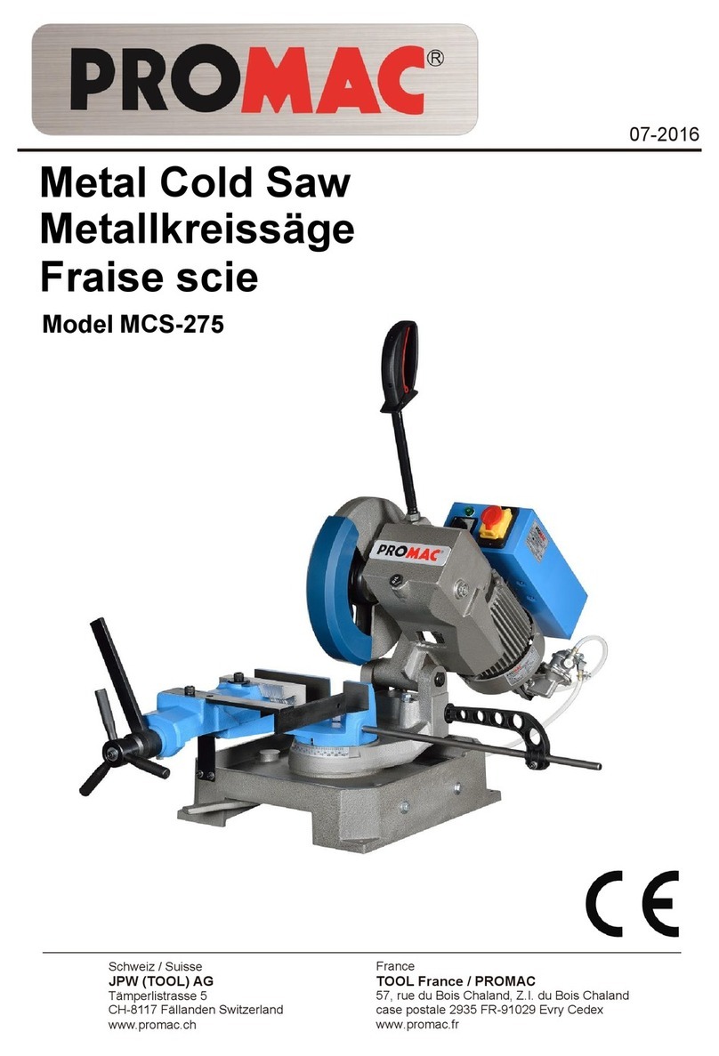
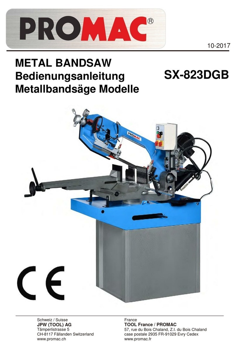
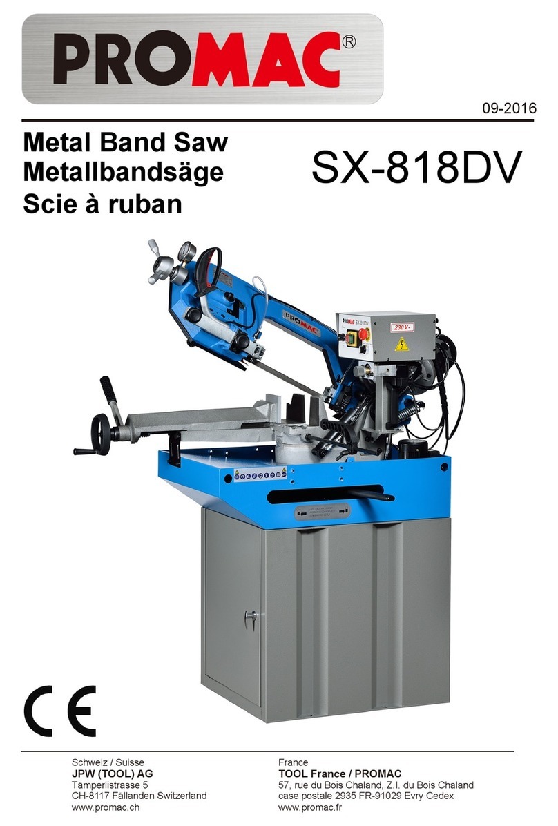
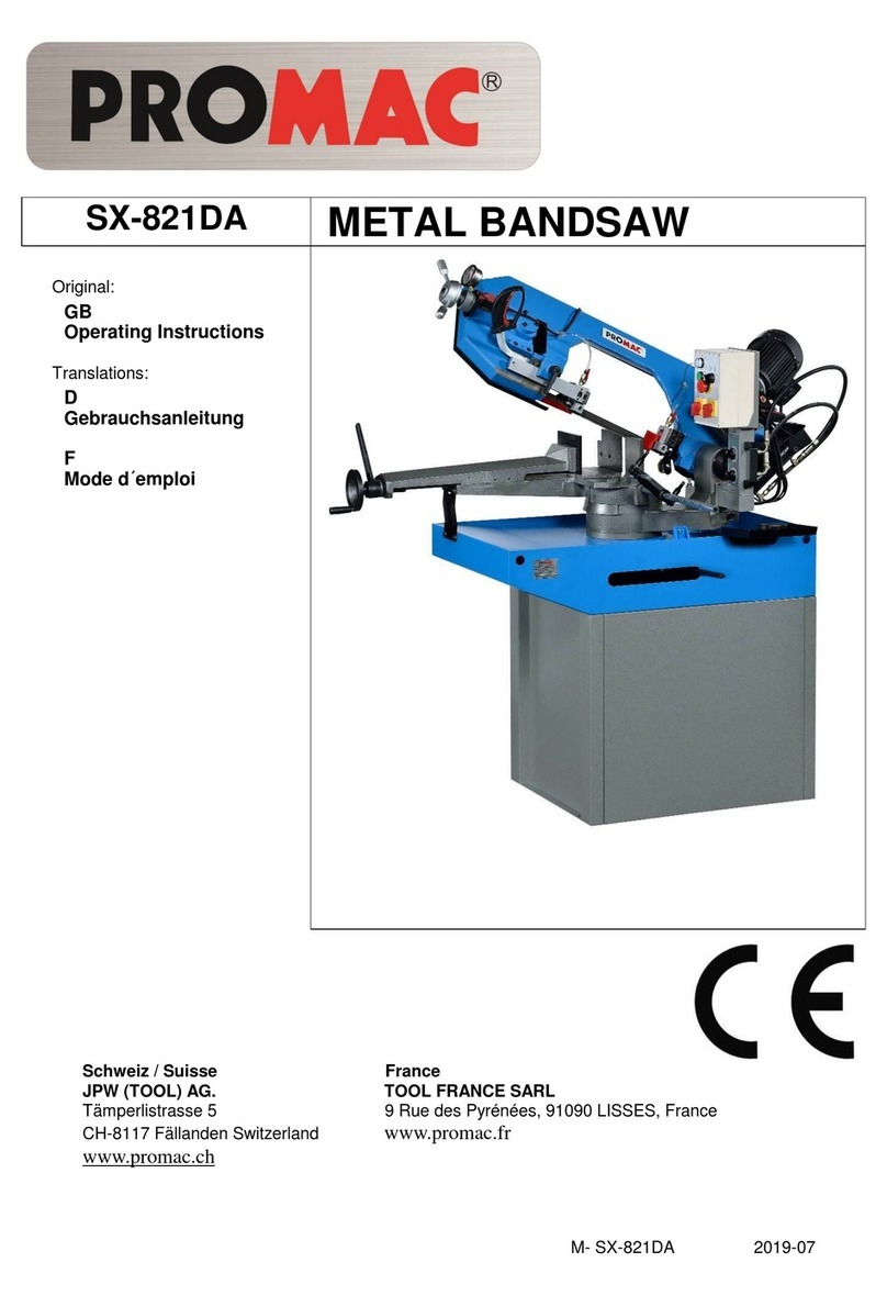
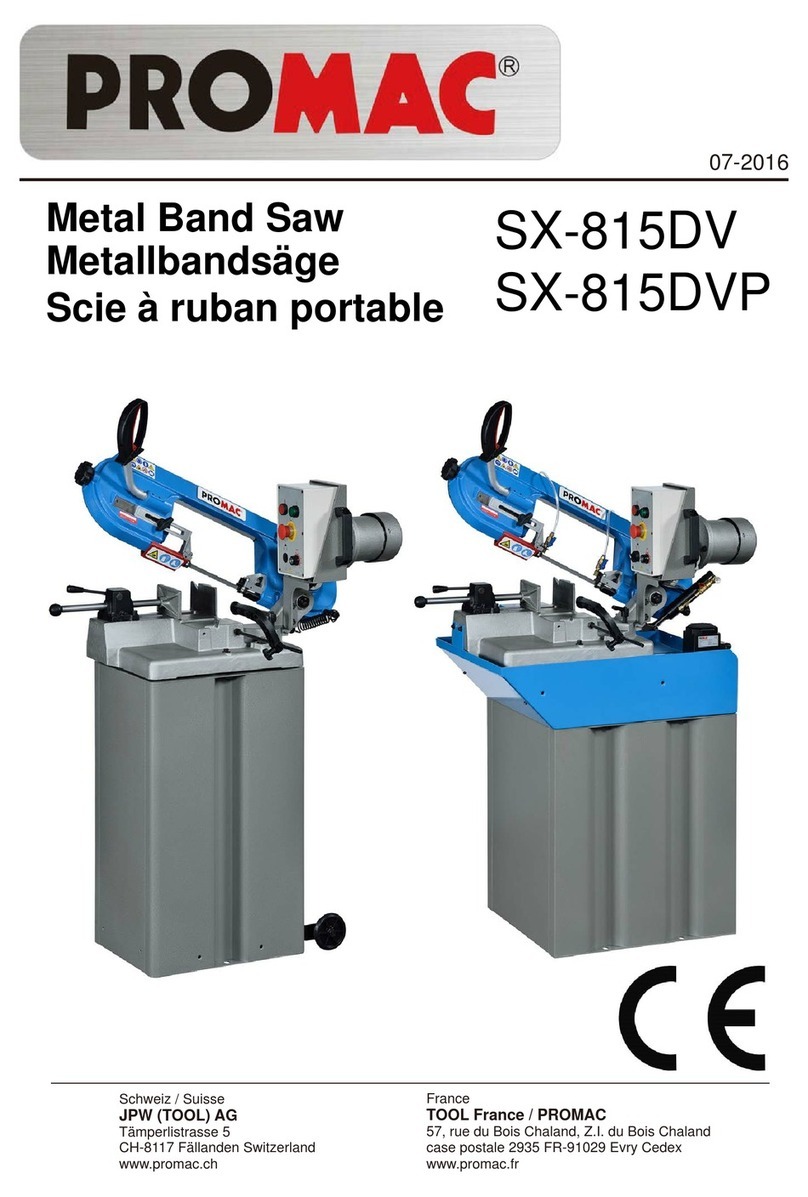
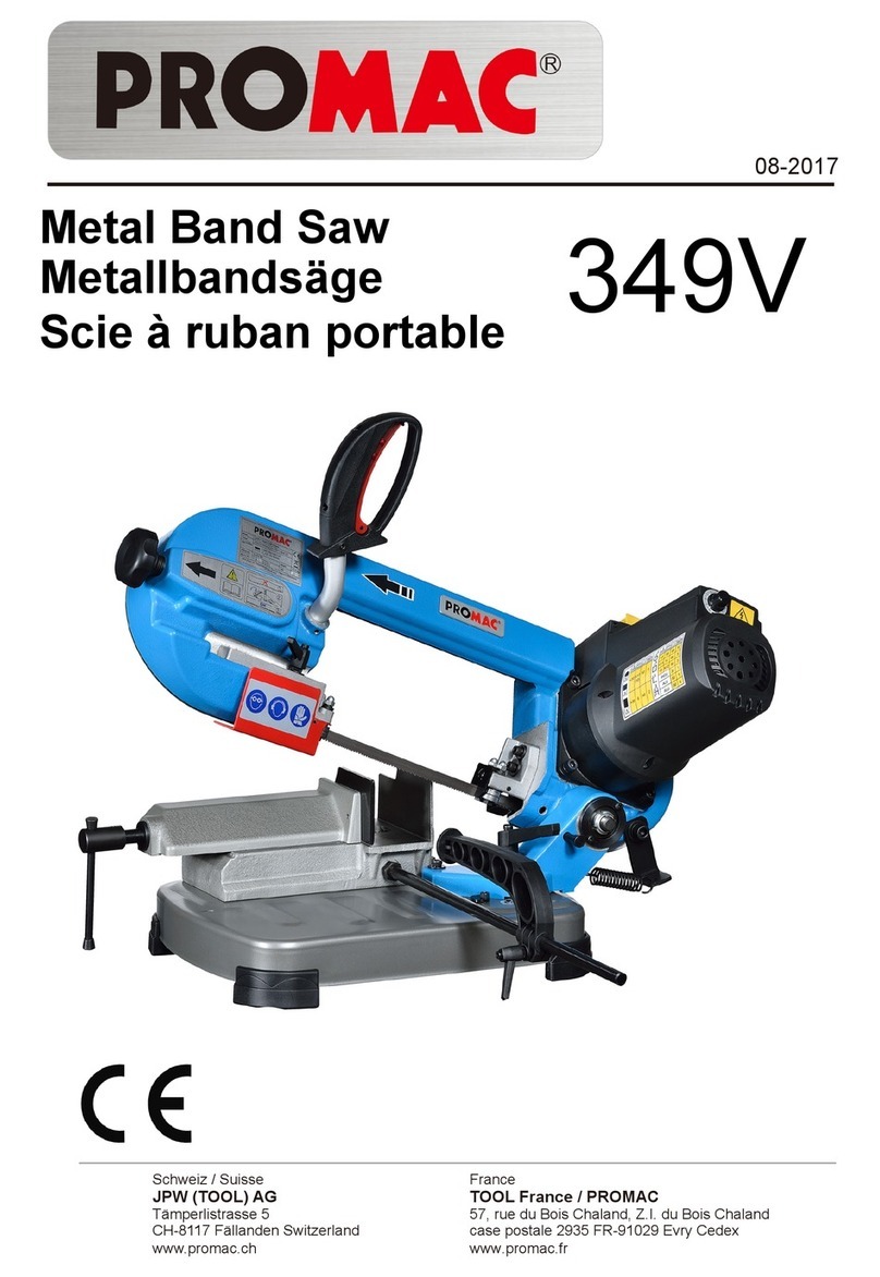
Promac SY-315 User manual

Metallkreissäge
Fraise scie
SY-315
SY-315L
Metal Cold Saw
Schweiz / Suisse
JPW (TOOL) AG
Tämperlistrasse 5
CH-8117 Fällanden Switzerland
www.promac.ch
France
TOOL France / PROMAC
57, rue du Bois Chaland, Z.I. du Bois Chaland
case postale 2935 FR-91029 Evry Cedex
www.promac.fr
07-2016

CE-Conformity Declaration
CE-Konformitätserklärung
Déclaration de Conformité CE
Product / Produkt / Produit:
Metal band saw
Metallbandsäge
Scie à ruban portable
SY-315 / SY-315L
Brand / Marke / Marque:
PROMAC
Manufacturer / Hersteller / Fabricant:
JPW (Tool) AG, Tämperlistrasse 5, CH-8117 Fällanden
Schweiz / Suisse / Switzerland
We hereby declare that this product complies with the regulations
Wir erklären hiermit, dass dieses Produkt der folgenden Richtlinie entspricht
Par la présente, nous déclarons que ce produit correspond aux directives suivantes
2006/42/EC
Machinery Directive
Maschinenrichtlinie
Directive Machines
2014/30/EU
electromagnetic compatibility
elektromagnetische Verträglichkeit
compatibilité électromagnétique
designed in consideration of the standards
und entspechend folgender zusätzlicher Normen entwickelt wurde
et été développé dans le respect des normes complémentaires suivantes
EN ISO 12100:2010
EN 13898:2003+A1:2009
EN 60204-1:2006+A1:2009
EN 61000-6-2:2005
EN 61000-6-4:2007+A1:2011
Responsible for the Documentation / Dokumentations-Verantwortung / Résponsabilité de Documentation:
Hansjörg Meier
Head Product-Mgmt. / Leiter Produkt-Mgmt. / Resp. Gestion des Produits
JPW (Tool) AG
2016-07-19 Alain Schmid, General Manager
JPW (Tool) AG, Tämperlistrasse 5, CH-8117 Fällanden
Schweiz / Suisse / Switzerland

SY-315 / SY-315L
GB - ENGLISH
Operating Instructions
Dear Customer,
Many thanks for the confidence you have shown in us with the purchase of your new machine. This manual has been prepared
for the owner and operators of a SY-315 / SY-315L metal circular saw to promote safety during installation, operation and
maintenance procedures. Please read and understand the information contained in these operating instructions and the
accompanying documents. To obtain maximum life and efficiency from your machine, and to use the machine safely, read this
manual thoroughly and follow instructions carefully.
…Table of Contents
1. Declaration of conformity
2. Warranty
3. Safety
4. Machine dimension
5. Getting to know your machine
6. Functional parts of the blade saw
7. Adjusting your machine
8. Recommendations and advice
9. Machine operation
10. Routine and special maintenance
11. Technical details
12. Material classification and choice of tools
13. Environmental protection
14. Available accessories
15. Troubleshooting
1. Declaration of conformity
On our own responsibility we hereby declare that this
product complies with the regulations* listed on page 2.
Designed in consideration with the standards**.
2. Warranty
The Seller guarantees that the supplied product is free
from material defects and manufacturing faults. This
warranty does not cover any defects which are caused,
either directly or indirectly, by incorrect use, carelessness,
accidental damage, repair, inadequate maintenance or
cleaning and normal wear and tear.
Guarantee and/or warranty claims must be made within
twelve months from the date of purchase (date of invoice).
Any further claims shall be excluded.
This warranty includes all guarantee obligations of the
Seller and replaces all previous declarations and
agreements concerning warranties.
The warranty period is valid for eight hours of daily use. If
this is exceeded, the warranty period shall be reduced in
proportion to the excess use, but to no less than three
months.
Returning rejected goods requires the prior express consent
of the Seller and is at the Buyer’s risk and expense.
Further warranty details can be found in the General Terms
and Conditions (GTC). The GTC can be viewed at
www.jettools.com or can be sent by post upon request.
The Seller reserves the right to make changes to the product
and accessories at any time.
3. Safety
3.1 Authorized use
This machine is designed for sawing machinable metal and
plastic materials only.
Machining of other materials is not permitted and may be
carried out in specific cases only after consulting with the
manufacturer.
Never cut magnesium-high danger to fire!
The workpiece must allow to safely be loaded and clamped
for machining.
The proper use also includes compliance with the operating
and maintenance instructions given in this manual.
The machine must be operated only by persons familiar with
its operation and maintenance and who are familiar with its
hazards.
The required minimum age must be observed
The machine must only be used in a technically perfect
condition.
When working on the machine, all safety mechanisms and
covers must be mounted.
In addition to the safety requirements contained in these
operating instructions and your country’s applicable
regulations, you should observe the generally recognized
technical rules concerning the operation of metalworking
machines.
3

SY-315 / SY-315L
Any other use exceeds authorization.
In the event of unauthorized use of the machine, the
manufacturer renounces all liability and the responsibility
is transferred exclusively to the operator.
3.2 General safety notes
Metalworking machines can be dangerous if not used
properly. Therefore the appropriate general technical
rules as well as the following notes must be observed.
Read and understand the entire instruction manual before
attempting assembly or operation.
Keep this operating instruction close by the machine,
protected from dirt and humidity, and pass it over to the
new owner if you part with the tool.
No changes to the machine may be made.
Daily inspect the function and existence of the safety
appliances before you start the machine.
Do not attempt operation in this case, protect the
machine by unplugging the mains cord.
Remove all loose clothing and confine long hair.
Before operating the machine, remove tie, rings, watches,
other jewellery, and roll up sleeves above the elbows.
Wear safety shoes; never wear leisure shoes or sandals.
Always wear the approved working outfit
Do not wear gloves while operating this machine.
For the safe handling of saw blades wear work gloves.
Wear goggles when working
Install the machine so that there is sufficient space for
safe operation and workpiece handling.
Keep work area well lighted.
The machine is designed to operate in closed rooms and
must be placed stable on firm and levelled ground.
Make sure that the power cord does not impede work and
cause people to trip.
Keep the floor around the machine clean and free of
scrap material, oil and grease.
Never reach into the machine while it is operating or
running down.
Stay alert!
Give your work undivided attention. Use common sense.
Keep an ergonomic body position.
Maintain a balanced stance at all times.
Do not operate the machine when you are tired.
Do not operate the machine under the influence of drugs,
alcohol or any medication. Be aware that medication can
change your behaviour.
Keep children and visitors a safe distance from the work
area.
Never leave a running machine unattended.
Before you leave the workplace switch off the machine.
Do not operate the electric tool near inflammable liquids or
gases.
Observe the fire fighting and fire alert options, for example
the fire extinguisher operation and place.
Do not use the machine in a dump environment and do not
expose it to rain.
Insure that the workpiece does not roll when cutting round
pieces.
Use suitable table extensions and supporting aids for difficult
to handle workpieces.
Remove cut and jammed workpieces only when motor is
turned off and the machine is at a complete standstill.
Work only with well sharpened tools.
Work only with well secured workpiece.
Specifications regarding the maximum or minimum size of
the workpiece must be observed.
Do not stand on the machine.
Never operate with the guards not in place – serious risk of
injury!
Connection and repair work on the electrical installation may
be carried out by a qualified electrician only.
Have a damaged or worn cord replaced immediately.
Make all machine adjustments or maintenance with the
machine unplugged from the power source.
Remove defective saw blades immediately
3.3 Remaining hazards
When using the machine according to regulations some
remaining hazards may still exist
The moving saw blade in the work area can cause injury.
Broken saw blades can cause injuries.
Thrown cutting chips and noise can be health hazards.
Be sure to wear personal protection gear such as safety
goggles and ear protection.
The use of incorrect mains supply or a damaged power cord
can lead to injuries caused by electricity.
4

SY-315 / SY-315L
4. Machine dimensions, Transport, Installation and
Dismantling
4.1 Machine dimensions
4.2 Transporting the machine
When transporting in its own packaging, use a forklift
truck or hand trolley.
4.3 Minimum requirements for housing the machine
- The main voltage and frequency complying with the
requirements for the machine’s motor.
- Environment temperature from –10°C to +50°C.
- Relative humidity not over 90%.
4.4 Information on fitting loose parts and accessories
Fit delivered parts
Fit the stop
Fit the wheel supports and align with the vice table.
4.5 Deactivating the machine
If the machine is to be inactive for a long period, prepare
the machine as follows:
1). Detach the plug from the electric supply panel
2). Release the saw blade
3). Release the head return spring
4). Empty the coolant tank
5). Carefully clean and grease the machine
6). If necessary, cover the machine.
4.6 Dismantling
General rules:
Before disposing of the machine, the machine should be
broken down and separated into the 3 categories as follows:
1) Cast iron or ferrous materials: These materials should be
of single composition, without combination or attachment to
other types of materials. This is a recyclable material. The
materials may be sent to metal scrap and recycling centers.
2) Electrical components: This includes cables and
electronic parts (magnetic cards, etc.). These materials may
be considered as urban waste. Give the materials to your
local public waste disposal service.
3) Old mineral, synthetic and/or mixed oils: Blend oils and
greases are special refuse. Have these collected by a
service specializing in oil disposal.
NOTE:
Standards and legislation for waste disposal is in a state
continuous change and evolution. The user must be
informed of current regulation for waste disposal of machine
tools, as they may differ from those described above. They
are to be considered as general guideline.
5. Getting to know your machine
5.1 Disk head assembly
Machine part composed of the parts that transmit movement
(motor, reduction unit), the lubricating coolant pump and the
electrical components.
A: Control Lever
A long angled lever with a handle grip and trigger switch for
starting, raising, and lowering the disk head
B: Transfer Case
The central part of the assembly, housing the gear system
and oil tank.
5

SY-315 / SY-315L
5.2 Machine base
A heavy cast iron structure that supports the head
assembly, vice system and collects the coolant.
5.3 Vice
The vice is the clamping system. Operations are
conducted by hand-wheel, which opens and closes the
vice jaws.
The clamping vice can beadjusted forward and backward
to clamp workpiece of various sizes.
5.4 Support roller
A device that support longer sized material. The roller
assists stock moving through the vice.
5.5 Stand
Support structure for the machine head assembly,
machine base and coolant system.
Support structure for the Machine Head Assembly and
Machine Base. The stand also stores the coolant system.
5.6. The coolant system
The coolant system is accommodated into the machine base.
6. Functional parts of the blade saw
6
A
B
C
D
E
F
G
K
H
I
J
1
2
3
4
5

SY-315 / SY-315L
A Push lever with trigger switch
B Mobile blade guard
C Saw blade
D Quick action stick lever
E Adjustment handle quick action sledge
F Adjustment level mitre setting of sawhead
G Machine foot with coolant
H Splash guard
I Longitudinal stop
J Control unit with
1 Stop button
2 Operating button
3 Emergency/off switch
4 Pump on/off switch
5 Rotations selector
K Reducer with 2-speed engine
7 Adjusting your machine
7.1 Anchoring the machine
Position the machine on a firm and level concrete floor.
Maintain a minimum distance of 800mm from the wall to
rear of the machine. Anchor the machine to the ground,
as shown in the diagram, using screws and expansion
plugs or sunken tie rods that connect through holes in the
base of the stand. Ensuring that it is sitting level (see
picture).
7.2 Unpacking
Remove packaging. Remove all accessories (A) and the
coolant system (B) from the pallet.
Lift the stand (C) and place into the intended working location
(D).
7.3 Mount the machine on the base or workplace.
This will require a crane or stacker truck with lifting ropes.
Carefully place the lifting rope (E) to the hooks (F, Fig 3b)
and carefully position the machine on the base or workplace.
7

SY-315 / SY-315L
- Place the machine on the top of the stand.
- Align the four holes (G) on the lower face of the
machine.
- Screw the spacer bolts into the threaded holes (G).
- Screw the nuts to the threaded holes and secure.
Install the coolant support:
- Attach the support plate (H) with 2 bolts M8x12 (I) like
shown in the picture.
Remove the oil fill transport plug (J) (only used for transport)
from gear transfer case.
Turn the control handle (L) with trigger switch (K) into the
threaded hole (J) and secure with nut in correct position.
8

SY-315 / SY-315L
Plug in the control handle cable into the open socket (M).
Use a wrench to screw in the cable connecter nut (N).
Attach the support roller (P) on the left side of the
machine base.
- Align the 2 slots (O) in the base of the support roller with
the matching screw holes on the base of the machine.
- Adjust the height of the support roller (P). Place a level
across the mouth of the vice and support roller. If a long
level in not available, use a straight bar or piece of
material then place a small level on top. Raise or lower
the support roller until level.
- Secure the 2 bolts (O).
Insert the thread end of the long rod (R) into the side of
the vice.
- Turn the long rod clockwise until snug.
- Use a wrench to turn the hex nut M12 (Q) on the long
rod, so that bar stop unit is secure.
Attach the cover plate (S) to machine stand.
- Place plate next to the hole at the base of the machine
stand.
- Align the plate holes and the stand holes.
- Use 4 screws M5x6 to secure onto place.
Apply an M6 washer to each of 2 M6x20 screws (U).
Secure pump (X) to tank (T) with prepared screws (U).
Place the hose clamp (V) onto the flow tube (W).
Connect the flow tube (W) to the hose connector (V).
Use a flat head screwdriver to tighten the hose clamp (V).
Attach the coolant system:
- Attach the coolant pump (X) with two screws M6x20 (U)
onto the coolant tank (T).
- Connect the flow tube (W) by using two hose clamps (V) to
the pump and hose connector.
9

SY-315 / SY-315L
- Install the pump system (1A) in the machine stand, with
the motor (X) facing in.
- Attach the L-beam (H) with 4 bolts M8x25.
- Connect the return hose (Y) to the machine base (1B)
and make sure it flows into the filter (Z).
- Attach the rear cover (1C) with 4 screws (1D):
- Attach the small splash guard (1E) in the front of the
machine base, using 2 screws M6x16 (1F).
Make sure it does not interfere with the machine vise
- Place the large splash guard (1G) to the rear of the
machine base. It can be positioned as needed.
10

SY-315 / SY-315L
8. Recommendations and advice
8.1 General advice before using the machine
- The machine has been designed to cut metal, used in
workshops, turner's shops and general mechanical
structural work.
- The machine model SY-315 (44/88 rpm) is suitable for
profiles and lighter workpieces.
- The machine model SY-315L (22/44 rpm) is suitable for
solid workpieces and high tensile material like chromium
steel.
- Limit the machine use to a single operator.
- Do not overload the machine when using it for the first
time to give the transmission time to run in.
Always check that the workpiece is securely clamped and
that long pieces are suitably supported.
- Do not use blades bigger than 315 mm.
- Always start the machine with a raised head and closed
vise.
- Make sure the saw blade is well-sharpened and has the
correct toothing for the workpiece.
The operator should stand in front of the machine using a
single hand to grip the control handle.
9. Machine operation
ATTENTION:
Before working on the machine (e.g. maintenance,
adjustment or repair works) it must be completely
disconnected from the mains supply.
9.1 Mitre angle
- Use the mitre lock lever (A) to release the disk head
assembly.
- Rotate the disk head assembly to the correct mitre
angle.
- Check the mitre angle on the angle indicator (B) below the
vice.
- Use the mitre lock lever (A) to lock in the mitre angle
9.2 Vice operation
The machine is fitted with a quick clamp system.
Use the vice hand-wheel (A) to approach the work-piece, but
leave an approximate 2 - 5mm gap between the mobile vice
jaw and the work-piece (C).
Then use the vice lock lever (B) to clamp and unclamp the
work-piece.
9.3 Loading the work piece
- Open the quick action sledge sufficiently.
- Measure and mark off the length of material desired to be
cut-off.
11

SY-315 / SY-315L
- Place the work-piece on the flat surface in between the
vice jaws.
- Align the workpiece on the saw blade and make sure
that the workpiece is positioned completely against the
rear clamp jaw.
- Tighten the workpiece as described under 9.2.
9.4 Setting cutting length
The length of the workpiece can be set with the
longitudinal stop.
- Set the desired workpiece length according to the scale
on the stopper bar (C).
- Insert the workpiece in the vice with the end of the
workpiece touching the stopper lug (B), then tighten the
adjustment screws (A)
- Tighten the workpiece with the quick action stick lever.
- Check the length of the workpiece.
9.5 Operation cycle
START
- Set the head to the desired angle.
- Open the vice enough.
- Adjust the fence.
- Load the work-piece.
- Clamp the work-piece.
- Set the desired rotations on the rev selector (5).
- Set the coolant switch (4) if necessary.
- Press the operating button (2).
- Grasp the control handle (G) and start the machine by
pressing the trigger switch (F).
Pull down the control handle (G). Apply a steady and
constant pressure.
After cut off
- Raise control handle slowly
- Release the trigger switch (F), machine will stop.
- Press the stop button (1)
- Use vice lever to open the vice
- Remove or feed the workpiece forward
9.6 Setting the mitre adjustment lever
If it is not possible to release or tighten the adjustment lever
of the mitre adjustment on the saw head sufficiently, then the
lever has to be repositioned.
- Release screw (A), then put the push with the screw bolts
(B) in the correct position on the mitre adjustment lever (C)
and tighten screw (A).
12

SY-315 / SY-315L
9.7 Changing the saw blade
Release the frame (B) of the movable chip protection (A)
so it moves freely.
- Place a piece of wood in the clamp and lower the saw
blade on top of it.
- Release the screw (C) with the blade key.
NOTE:
Left-hand thread - turn clockwise!
- Remove the blade flange (E) and saw blade (D).
Clean all parts, fit a new saw blade and blade flange, and
tighten the blade screw.
9.8 Cleaning and accessing the coolant system
- Pull out the drain hose from the filter (A).
- Pull out the coolant tank from the coolant platform in the
stand.
- Remove the filter (A) from the tank
- Pour out the coolant, wash out the dirt and debris.
Replace the filter (A), replace the coolant tank in reverse
order of removal.
Fill with coolant solution of 1:10 ratio of coolant to water.
10. Routine and special maintenance
THE MAINTENANCE SCHEDULE HAS BEEN DIVIDED
INTO DAILY, WEEKLY, MONTHLY, AND SIX-MONTHLY
INTERVALS. NEGLECTING THE MACHINE
MAINTENANCE WILL RESULT IN PREMATURE WEAR
AND POOR PERFORMANCE.
10.1 Daily maintenance
Make a general cleaning by removing dust and shavings
from the machine.
Top off the coolant.
Inspect the disk/saw blade for wear.
Raise the head into a high position to reduce stress on the
return spring.
Check that the shields and emergency stops are in good
working order.
10.2 Weekly maintenance
Thoroughly clean the machine including the coolant tank.
Clean and grease the vice screw and sliding surfaces.
Clean the housing for disk/saw blade.
Sharpen the saw teeth.
10.3 Monthly maintenance
Check that all screws on the motor, the pump, the vice jaws,
and the guard are tight and secure.
13

SY-315 / SY-315L
Grease the hinge pin for the head assembly.
10.4 Semi annual maintenance
- Check the passage of the equipotential bonding
protection circuit.
- See chapter 10.7 reduction unit.
10.5 Oils for lubricating coolant
Considering the vast range of products on the market, the
user can choose the one most suited to his own
requirements, using as reference the type SHELL LUTEM
OIL ECO.
THE MINIMUM PERCENTAGE OF OIL DILUTED IN
WATER IS 8~10%.
We recommend the following products:
Art. No: 9179 coolant 5kg
Art. No: 100385 way lube oil 1lt
Art No: 100382 gear box oil 1lt
10.6 Oil disposal
Oil products must be disposed in a proper manner
following local regulations (see chapter 4.6).
10.7 Reduction gearbox
The gear box oil hasto be changed periodically. The first
oil change is to be carried out after 6 months, and then
after that once a year.
Change the oil as follows:
- Disconnect the machine from the mains supply.
- Put the saw blade in a vertical position.
- Unscrew the lever from the gear head
- Remove the oil drain screw (A) and allow the oil to drain
off into a container.
Replace the screw (A) once all the oil has drained off.
- Move the saw arm into a raised position.
Pourfresh oil (item 100382) into the filler hole (thread hole
on lever) - quantity 0.3 l.
- Fit and tighten the lever.
10.8 Special Maintenance
Special maintenance operations must be carried out by
skilled personnel. However, we advice contacting dealer
and/or importer the term special maintenance also covers the
resetting of protection and safety equipment and devices.
11. Technical details
11.1 Table of cutting and technical details
Cutting capacity in mm
90°50 10082x82 110x70
45°50 90 80x80 85x70
Power supply 3~400V, PE, 50Hz
Main motor 1,3 kW
Cooling pump 0,1 kW
Saw blade dimension Ø315 / Ø32 mm
Blade speed SY-31544/88 rpm
Blade speed SY-315L22/44 rpm
Vice opening max. 120 mm
Coolanttank 5 lt
Machine dimensions (LxWxH) 1020 x 990 x 1830 mm
Machine weight with stand170 kg
11.2 Noise emission
Acoustic pressure level (EN ISO 11202):
Idling Lpa 70,0 dB(A)
The specified values are emission levels and are not
necessarily to be seen as safe operating levels.
As workplace conditions vary, this information is intended to
allow the user to make a better estimation of the hazards and
risks involved only.
12. Material classification and choice of tools
12.1 Rounding of teeth
A carefully broken in blade lasts much longer and gives
better performance.
14

SY-315 / SY-315L
To break in your new blade, run it at only 30% of normal
pressure for ten minutes.
Then gradually increase to normal pressure.
12.2 Blade structure
Bi-metal blades are the most commonly used.
12.3 Blade type
They differ essentially in their constructive characteristics:
- Shape and angle of teeth
- Teeth pitch
- Off-set
Choose a toothing that is appropriate to the workpiece
being processed. Ideally, at least 3 teeth should be in
action at the same time.
The toothing should not be smaller than necessary, as
the cutting speed is reduced if there are too many small
teeth working on the workpiece simultaneously, which
causes the saw band to wear more quickly, and makes
the cuts crooked and distorts them.
The following table shows the approximate toothing of
the saw bands for a specific material thickness. For
further information please contact your saw band dealer.
Comments
10/14 toothing provides good cutting results for thin-walled
pipes and profiles.
The choice of toothing (i.e. the number of teeth per inch)
should be such that at least 3 teeth are always in action at
the same time.
Feed pressure selection:
A good indication of proper feed pressure is the shape of the
cutting chips.
Perfect:
Loose curled chips
If the chips are thin or powdered increase the feed pressure.
If the chips are burned reduce the cutting speed and
decrease the feed pressure.
Fine Tooth Pitch:
- For thin wall materials (tubes and profiles)
Coarse Tooth Pitch:
- For large cross-sections
- For soft materials (aluminum)
When cutting thick material, a coarse Tooth Pitch “T” is
needed to accommodate the big chips
15

SY-315 / SY-315L
12.4 Materials and characteristics
MATERIALS CHARACTERISTICS
I
UNI
D
DIN
F
AF NOR
GB
SB
USA
AISI-SAE
Hardness
BRINELL
HB
σ=N/mm2
Construction
Steel
Fe360
Fe430
Fe510
St37
St44
St52
E24
E28
E36
----
43
50
----
----
----
116
148
180
360÷480
430÷560
510÷660
Carbon Steel
C20
C40
C50
C60
CK20
CK40
CK50
CK60
XC20
XC42H1
----
XC55
060 A 20
060 A 40
----
060 A 62
1020
1040
1050
1060
198
198
202
202
540÷690
700÷840
760÷900
830÷980
Spring Steel 50CrV4
60SiCr8
50CrV4
60SiCr7
50CV40
----
735 A 50
----
6150
9262
207
224
1140÷1330
1220÷1400
Alloyed steels for
hardening and
tempering and for
nitriding
35CrMo4
39NiCrMo4
41CrAlMo7
34CrMo4
36CrNiMo4
41CrAlMo7
35CD4
39NCD4
40CADG12
708 A 37
----
905 M 39
4135
9840
----
220
228
232
780÷930
880÷1080
930÷1130
Alloyed
casehardening
steels
18NiCrMo7
20NiCrMo2
----
21NiCrMo2
20NCD7
20NCD2
En 325
805 H 20
4320
4315
232
224
760÷1030
690÷980
Alloyed steel for
bearings
100Cr6 100Cr6 100C6 534 A 99 52100 207 690÷980
Tool steel
52NiCrMoKU
C100KU
X210Cr13KU
58CrMo1713
56NiCrMoV7
C100K
X210Cr12
----
----
----
Z200C12
Y60SC7
----
BS 1
BD2-BD3
----
----
S-1
D6-D3
S5
244
212
252
244
800÷1030
710÷980
820÷1060
800÷1030
Stainless steel
X12Cr13
X5CrNi1810
X8CrNi1910
X8CrNiMo1713
4001
4301
----
4401
----
Z5CN18.09
----
Z6CDN17.12
----
304 C 12
----
316 S 16
410
304
----
316
202
202
202
202
670÷885
590÷665
540÷685
490÷685
Copper alloys ,
Special brass,
Bronze
Aluminium copper alloy G-CuAl11Fe4Ni4, UNI 5275
Special manganese/silicon-brass G-CuZn36Si1Pb1, UNI5038
Manganese bronze SAE43-SAE430
Phosphor bronze G-CuSn12, UNI 7013/2a
220
140
120
100
620÷685
375÷440
320÷410
265÷314
Cast iron
Gray pig iron G25
Spheroidal graphite cast iron GS600
Malleable cast iron W40-05
212
232
222
245
600
420
11. Environmental protection
Protect the environment.
Your appliance contains valuable materials which can be recovered or recycled. Please leave it at a specialized institution.
12. Available accessories
Refer to the Pricelist
16

SY-315 / SY-315L
13. Troubleshooting
This chapter lists the probable faults and malfunctions that could occur while the machine is being used and suggests possible
remedies for solving them.
The first paragraph provides diagnosis for TOOLS and CUTS, the second for ELECTRICAL COMPONENTS.
13.1 Blade and cut diagnosis
FAULT PROBABLE CAUSE REMEDY
TOOTH BREAKAGE
Too fast advance
Wrong cutting speed
Wrong tooth pitch
Low quality disk
Ineffective gripping of the part in the vice.
Previously broken tooth left in the cut.
Cutting resumed on a groove made
previously.
Insufficient lubricating refrigerant or
wrong emulsion.
Sticky accumulation of material on the
disk.
Decrease advance, exerting less cutting
pressure.
Change disk speed and/or diameter.
See chapter “ Material classification and
choice of disks” and the Table of cutting
speed s according to disk diameter.
Choose a suitable disk.
See chapter “ Material classification and
choice of disks”.
Use a better quality disk.
Check the gripping of the part.
Accurately remove all the parts left in.
Make the cut elsewhere, turning the part.
Check the level of the liquid in the tank.
Increase the flew of lubricating
refrigerant, checking that the hole and
the liguid outlet pipe are not blocked.
Check the blend of lubricating coolant
and choose a better quality disk.
PREMATURE DISK
WEAR
Wrong running in of the disk .
Wrong cutting speed.
Unsuitable tooth profile.
Wrong tooth pitch.
Low quality disk.
Insufficient lubricating refrigerant.
See chapter “ Material classification and
choice of disks” in the paragraph on
Running in the disk.
Change disk speed and / or diameter.
See Chapter “ Material classi
fication and
choice of disks” and the Table of cutting
speeds according to disk diameter.
Choose a suitable disk. See Chapter
“ Material classification and choice of
disks” in the paragraph on Type of disks.
Choose a suitable disk.
See Chapter “ Material classification and
choice of disks”.
Use a better quality disk.
Check the level of the liquid in the tank.
Increase the flow of lubricating
refrigerant, checking that the hole and
the liquid outlet pipe are not blocked.
17

SY-315 / SY-315L
FAULT PROBABLE CAUSE REMEDY
CHIPPED DISK
Hardness, shape or flaws in the material
(oxides, inclusions, lack of homogeneity,
etc…)
Wrong cutting speed.
Wrong tooth pitch.
Vibrations
Disk incorrectly sharpened.
Low quality disk.
Incorrect emulsion of the lubricating
Refrigerant.
Reduce the cutting pressure and/or the
advance.
Change disk speed and/or diameter. See
Chapter ”Material classification and
choice of disks” and the Table of cutting
speeds according to disk diameter.
Choose a suitable disk.
See Chapter “Material classification and
choice of disks”.
Check gripping of the part.
Replace the disk with one that is more
suitable and correctly sharpened.
Use a better quality disk.
Check the percentage of water and oil in
the emulsion.
DISK VIBRATION
Wrong tooth pitch.
Unsuitable tooth profile.
Ineffective gripping of the part in the vice.
Dimensions of the solid section too large
with respect to the maximum admissible
cutting dimensions.
Disk diameter incorrect and/or too large.
Choose a suitable disk.
See Chapter “Material classification and
choice of disks”.
Choose a suitable disk.
See Chapter “Material classification and
choice of disks” in the paragraph on Type
of disks.
Check the gripping of the part.
Abide by the instructions.
Decrease the disk diameter, adapting it
to the dimensions of the part to be cut,
the cutting part of the disk must not be
too large for the shape of the part to be
cut.
RIDGES ON THE
CUTTING SURFACE
Disk diameter incorrect and/ or too large.
Ineffective gripping of the part in the vice.
Too fast advance.
Disk teeth are worn.
Insufficient lubricating refrigerant.
Toothing does not unload shavings well.
Decrease the disk diameter, adapting it
to the dimensions of the part to be cut,
the cutting part of the disk must not be
too large for the shape of the part to be
cut. Check the gripping of the part.
Decrease advance, exerting less cutting
pressure.
Sharpen the tool.
Check the level of the liquid in the tank.
Increase the flow of lubricating
refrigerant, checking that the hole and
the liquid outlet pipe are not blocked.
Choose a blade with a larger tooth pitch
that allows better unloading of shavings
and that holds more lubricating
refrigerant.
18

SY-315 / SY-315L
FAULT PROBABLE CAUSE REMEDY
CUT OFF THE
STRAIGHT
Too fast advance.
Ineffective gripping of the part in the vice.
Disk head off the straight.
Disk sides differently sharpened.
Disk thinner than the commercial
standard.
Dirt on the gripping device.
Decrease advance, exerting less cutting
pressure.
Check the gripping of the part which may
be moving sideways.
Adjust the head.
Choose tool quality carefully in every
detail as regards type and construction
characteristics.
Carefully clean the laying and contact
surfaces.
BLADE STICKS IN
THE CUT
Too fast advance.
Low cutting speed.
Wrong tooth pitch.
Sticky accumulation of material on the
disk.
Insufficient lubricating refrigerant.
Decrease advance, exerting less cutting
pressure.
Increase speed.
Choose a suitable disk.
See Chapter “Material classification and
choice of disks”.
Check the blend of lubricating coolant
and choose a better quality disk.
Check the level of the liquid in the tank.
Increase the flow of lubricating
refrigerant, checking that the hole and
the liquid outlet pipe are not blocked.
19

SY-315 / SY-315L
DE - DEUTSCH
Gebrauchsanleitung
Sehr geehrter Kunde,
vielen Dank für das Vertrauen, welches Sie uns beim Kauf Ihrer neuen Maschine entgegengebracht haben. Diese Anleitung
ist für den Inhaber und die Bediener zum Zweck einer sicheren Inbetriebnahme, Bedienung und Wartung der
Metallkreissäge SY-315 / 315L erstellt worden. Beachten Sie bitte die Informationen dieser Gebrauchsanleitung und der
beiliegenden Dokumente. Lesen Sie diese Anleitung vollständig, insbesondere die Sicherheitshinweise, bevor Sie die
Maschine zusammenbauen, in Betrieb nehmen oder warten. Um eine maximale Lebensdauer und Leistungsfähigkeit Ihrer
Maschine zu erreichen befolgen Sie bitte sorgfältig die Anweisungen.
Inhaltsverzeichnis
1. Konformitätserklärung
2. Garantieleistungen
3. Sicherheit
4. Maschinenabmessungen, Transport, Montage,
Demontage
5. Die Funktionsteile der Maschine
6. Bedienelemente der Maschine
7. Einrichten der Maschine
8. Wie man die Kreissäge korrekt verwendet
9. Einstellung der Maschine
10. Routine und Sonderwartungen
11. Technische Daten
12. Werkstoffeinteilung und Wahl des Werkzeugs
13. Umweltschutz
14. Lieferbares Zubehör
15. Fehlersuche
1. Konformitätserklärung
Wir erklären in alleiniger Verantwortlichkeit, dass dieses
Produkt mit den auf Seite 2 angegebenen Richtlinien*
übereinstimmt.
Bei der Konstruktion wurden folgende Normen**
berücksichtigt.
2. Garantieleistungen
Der Verkäufer garantiert, dass das gelieferte Produkt frei
von Material- und Fertigungsfehlern ist. Diese Garantie
trifft nicht auf jene Defekte zu, welche auf direkten oder
indirekten, nicht fachgerechten Gebrauch, Unachtsamkeit,
Unfallschaden, Reparatur, mangelhafte Wartung bzw.
Reinigung sowie normalen Verschleiß zurückzuführen
sind.
Garantie- bzw. Gewährleistungs-ansprüche müssen
innerhalb von 12 Monaten ab dem Verkaufsdatum
(Rechnungsdatum) geltend gemacht werden.
Weitergehende Ansprüche sind ausgeschlossen.
Die vorliegende Garantie umfasst sämtliche
Garantieverpflichtungen seitens des Verkäufers und
ersetzt alle früheren Erklärungen und Vereinbarungen
betreffend Garantien.
Die Garantiefrist gilt für eine tägliche Betriebszeit von 8
Stunden. Wird diese überschritten, so verkürzt sich die
Garantiefrist proportional zur Überschreitung, jedoch
höchstens auf 3 Monate.
Die Rücksendung beanstandeter Ware bedarf der
ausdrücklichen vorherigen Zustimmung vom Verkäufer
und geht auf Kosten und Gefahr des Käufers.
Die ausführlichen Garantieleistungen sind den
Allgemeinen Geschäftsbedingungen (AGB) zu
entnehmen. Die AGB sind unter www.jettools.com
einzusehen oder werden auf Anfrage per Post zugestellt.
Der Verkäufer behält sich das Recht vor, jederzeit
Änderungen am Produkt und Zubehör vorzunehmen.
3. Sicherheit
3.1 Bestimmungsgemäße Verwendung
Die Maschine ist vorgesehen zum Sägen von
zerspanbaren Metallen und Kunststoffen.
Die Bearbeitung anderer Werkstoffe ist nicht zulässig bzw.
darf in Sonderfällen nur nach Rücksprache mit dem
Maschinenhersteller erfolgen.
Niemals Magnesium zerspanen-
Hohe Feuergefahr!
Es dürfen nur Werkstücke bearbeitet werden welche
sicher aufgelegt und gespannt werden können.
Die bestimmungsgemäße Verwendung beinhaltet auch
die Einhaltung der vom Hersteller angegebenen Betriebs-
und Wartungsanweisungen.
Die Maschine darf ausschließlich von Personen bedient
werden, die mit Betrieb und Wartung vertraut und über
die Gefahren unterrichtet sind.
Das gesetzliche Mindestalter ist einzuhalten.
20
This manual suits for next models
1
Table of contents
Languages:
Other Promac Saw manuals

Promac
Promac SY-350-ALU Service manual

Promac
Promac SX-815DVP User manual

Promac
Promac VBS-1610 Service manual

Promac
Promac 347V Service manual

Promac
Promac SX-821DA User manual

Promac
Promac MBS-910CS User manual

Promac
Promac 348C User manual

Promac
Promac 349V User manual

Promac
Promac SX-818DV User manual

Promac
Promac SY-350V User manual
Popular Saw manuals by other brands

Weber mt
Weber mt SM 82-3 Operating and maintenance manual

Bosch
Bosch GCM18V-12GDCN Operating/safety instructions

Makita
Makita SP6000 instruction manual

Chicago Electric
Chicago Electric 68829 Owner's manual & safety instructions

Hafco Woodmaster
Hafco Woodmaster SB-12 Operator's manual

DeWalt
DeWalt D27113 user manual