Promac 348C User manual

Metallbandsäge 05-2016
348C
Bedienungsanleitung
Inhaltsverzeichnis
2CE-Konformitäts-Zertifikat
3 - 4 Sicherheitsvorschriften
5Technische Daten, Maschinenbeschrieb
6Motorschutz, Auspacken
Elektrische Anlage, Auspacken
7-8 Bedienung
9Einstellungen
10 Wartung
21 Elektrische Anlage
22-23 Ersatzteilzeichnung
24-25 Ersatzteillisten
26 Garantieschein
Instruction manual
Index
2EC declaration of conformity
11-12 SafetyInformation
13-14 Special safety rules for the saw
15 Power supply
16 Specifications, description of
the machine
17 Quick Vice, unpacking
18-19 Use
20 Settings
21 Electrical Installation
22-23 Exploded View
24-25 List of spare parts
26 Guarantee certificate
Schweiz / Suisse
JPW (TOOL) AG
Tämperlistrasse 5
CH-8117 Fällanden Switzerland
www.promac.ch
France
TOOL France / PROMAC
57, rue du Bois Chaland, Z.I. du Bois Chaland
case postale 2935 FR-91029 Evry Cedex
www.promac.fr
Metallbandsäge
Portable metal band saw
Option 10048
Maschinenstand

CE-Konformitätserklärung
EC declaration of conformity
Produkt / Product:
Me
t
allbandsäge
Portable metal band
saw
348C
Marke / Brand:
PROMAC
Hersteller / Maker:
JPW (Tool) AG, Tämperlistrasse 5
,
CH-8117 Fällanden,
S
wi
t
zerland
Wir erklären hiermit, dass dieses Produkt der folgenden Richtlinie en
t
sprich
t
We hereby declare that this product meets the following directives
2006/42/EC
Maschinenrich
t
lnie
Machines Directives
2014/30/EU elek
tr
omagne
t
ische
Verträglichkeit electromagnetic
compatibility
2014/35/EU Niedervol
t
Direktiven Low-Voltage
Directives
und entspechend folgender zusätzlicher Normen entwickelt wurde
and was developed in compliance with the following additional standards
EN ISO 12100
EN 13898
EN 60204-1
EN 55011
Technical file compiled by:
Hansjörg Meier, JPW (Tool) AG
Leiter Produkt-Management, Head of Product Management
2016-03-03 Alain Schmid, General Manager
JPW (Tool) AG, Tämperlistrasse 5, CH-8117 Fällanden, Switzerland

Allgemeine Sicherheitsvorschriften
Hinweis: Das Nichtlesen dieser Anweisungen kann schwere Verletzungen zur Folge haben.
Wie bei allen Maschinen sind auch bei dieser Maschine beim Betrieb und der Handhabung maschinen-
typische Gefahren gegeben. Die aufmerksame Bedienung und der richtige Umgang mit der Maschine
verringern wesentlich mögliche Unfallgefahren. Werden die normalen Vorsichtsmassnahmen missachtet,
sind Unfallgefahren für den Bedienenden unausweichlich.
DieMaschinewurdenurfürdiegegebenenVerwendungsartenangelegt.WirlegenIhnendringendnahe,die
Maschine weder abgeändert noch in einer Art und Weise zu betreiben, für die sie nicht ausgelegt wurde.
Sollten Sie etwelche Fragen zum Betrieb der Maschine haben, wenden Sie sich bitte zuvor an den PRO-
MAC-Fachhändler, der Ihnen weiterhelfen kann, sollte Ihnen die Bedienungsanleitung keinen Aufschluss
geben.
ALLGEMEINE REGELN ZUM SICHEREN UMGANG MIT MASCHINEN
1. Zur eigenen Sicherheit immer erst die Bedienungsanleitung lesen, bevor die Maschine in Betrieb gesetzt
wird. Die Maschine, deren Bedienung und Betriebsgrenzen kennenlernen sowie deren spezifische Gefahren
erkennen.
2. Schutzabdeckungen in betriebsfähigem Zustand halten und nicht abbauen.
3. Elektrisch betriebene Maschinen mit einem Netzanschlussstecker mit Schutzkontakt immer an eine Steck-
dose mit Schutzkontakt (Erdung) anschliessen. Werden Zwischenstecker ohne Schutzkontakt verwendet,
muss der Schutzkontaktanschluss zur Maschine unbedingt hergestellt werden. Die Maschine niemals ohne
Schutzkontaktanschluss (Erdung) betreiben.
4. Lose Spannhebel oder Schlüssel immer von der Maschine entfernen. Ein Verhalten entwickeln, dass immer
vor dem Einschalten der Maschine geprüft wird, ob alle losen Bedienelemente entfernt wurden.
5. Arbeitsbereich hindernisfrei halten. Verstellte Arbeitsbereiche und Arbeitsflächen fordern Unfälle geradezu
heraus.
6. Maschine nicht in gefahrvoller Umgebung betreiben.Angetriebene Maschine nicht in feuchten oder nassen
Räumen betreiben oder diese dem Regen aussetzen. Arbeitsfläche und Bereich immer gut beleuchten.
7. Kinder und Besucher von der Maschine fernhalten. Kinder und Besucher immer in sicherem Abstand zum
Arbeitsbereich halten.
8. Die Werkstatt oder den Arbeitsraum vor unbefugtem Betreten absichern. Kindersicherungen in Form von
verschliessbaren Riegeln, absperrbaren Hauptschaltern etc. anbringen.
9. Maschine nicht überlasten. Die Arbeitsleistung der Maschine wird besser und der Betrieb sicherer, wenn
diese in den Leistungsbereichen betrieben wird, für welche sie ausgelegt ist.
10. Anbaugeräte nicht für Arbeiten einsetzen, für welche sie nicht ausgelegt sind.
11. RichtigeArbeitskleidung tragen; lose Kleidung, Handschuhe, Halstücher, Ringe, Hals- oder Handketten oder
anderen Schmuck vermeiden. Diese könnten sich in bewegenden Maschinenteilen verfangen. Schuhe mit
rutschfesten Sohlen tragen. Eine Kopfbedeckung tragen, die lange Haare vollständig abdeckt.
12. Immer eine Schutzbrille tragen. Hier gemäss den Unfallverhütungsvorschriften verfahren. Ebenso eine
Staubmaske bei Arbeiten mit Staubanfall tragen.
13. Werkstücke festklemmen. Zum Halten des Werkstücks immer einen Schraubstock oder eine Spannvorrich-
tung verwenden. Das ist sicherer als mit der Hand, und es stehen beide Hände zum Bedienen der Maschine
frei.
14. Auf Standsicherheit achten. Fussstellung und körperliche Balance immer so halten, dass der sichere Stand
gewährleistet ist.
3

Allgemeine Sicherheitsvorschriften
15. Maschine immer in einwandfreiem Zustand halten. Hierzu die Schneidflächen scharf und sauber für die
optimale Leistung halten. Die Betriebsanweisung für die Reinigung, das Schmieren und den Wechsel von
Anbaugeräten beachten.
16. Maschine immer vom Netz trennen, bevor Wartungsarbeiten oder der Wechsel von Maschinenteilen, wie
Sägeblatt, Schneidwerkzeuge etc. erfolgen.
17. Nur das empfohlene Zubehör verwenden. Dazu die Anweisungen in der Bedienungsanleitung beachten.
Die Verwendung von ungeeignetem Zubehör birgt Unfallgefahren in sich.
18. Vemeiden Sie ein unbeabsichtigtes Inbetriebsetzen. Immer vor dem Herstellen des Netzanschlusses prüfen,
ob der Betriebsschalter in der Stellung AUS steht.
19. Niemals auf der Maschine stehen. Schwere Verletzungen sind möglich, falls die Maschine kippt oder in
Berührung mit dem Schneidwerkzeug kommt.
20. Schadhafte Maschinenteile prüfen. Beschädigte Schutzvorrichtungen oder andere Teile sollten vor dem
weiteren Betrieb einwandfrei repariert oder ausgetauscht werden.
21. Maschine nie während des Betriebs verlassen. Immer die Netzversorgung abschalten. Maschine erst ver-
lassen, wenn diese vollständig zum Stillstand gekommen ist.
22. Alkohol, Medikamente, Drogen: Maschine nie unter Einfluss von Alkohol, Medikamenten oder Drogen
bedienen.
23. Sicher stellen, dass die Maschine von der Netzversorgung getrennt ist, bevorArbeiten an den elektrischen
Anlage, am Antriebsmotor etc. erfolgen.
Hinweise zur Arbeitssicherheit
Transport der Maschine
1. Die Maschine wiegt 23kg.
2. Für den Transport geeignete Transportmittel verwenden.
Arbeitsplatz
1. Die Beleuchtung und Belüftung des Arbeitsraumes muss ausreichend sein.
2. Die Beleuchtung für ein sicheres Arbeiten muss 300 LUX betragen.
Lärmtest
Gemäß Punkt 1.7.4f der Maschinen-Richtlinien 89/392 EG
Es wurden 4 Messungen der Maschine bei Leerbetrieb vorgenommen:
- Das Mikrophon wurde am Kopf des Bedieners in einer mittleren Höhe angebracht.
- Der Dauergeräuschpegel betrug unter 70 dB (A).
- Der maximale Geräuschpegel C wurde immer unterhalb 130 dB gemessen.
ANMERKUNG: bei Maschinenbetrieb schwankt die Geräuschstärke je nach Art der verarbeitenden Materi-
alien. Der Bediener wird daher die Intensität abschätzen und die verantwortlichen Personen mit geeigneten
Schutzmittel im Sinne des DL.vo 277/1991 ausrüsten müssen.
Elektrischer Netzanschluss
1. Die Maschine Modell 348C wird mit einem Netzkabel mit Stecker geliefert, 230V, 50Hz.
2. Die Absicherung muss min. 10 A sein.
3. Die genauen elektrischen Daten finden Sie auf dem Typenschild der Maschine und dem elektrischen Plan,
der dieser Anleitung beiliegt.
4. ACHTUNG: Für alle Service- oder Umrüstarbeiten sowie Reparaturen ist die Maschine vom elektrischen
Netz zu trennen (Stecker ausziehen).
4

Technische Daten
Bandmotor......................230V, 0.38kW, 4A
Bandgrösse.................... 1470 x 13 x 0.65mm
Bandgeschwindigkeit...... 45m/Min.
Abmessungen L/B/H ...... 720 x 390 x 460mm
Gewicht ..........................23kg
Schnittkapazitäten mm
90°
rund
rechteck
45°
rund
rechteck
100
100x150
60
60x90
Maschinenbeschrieb
1. Die PROMAC Metallbandsäge Modell 348C ist mit 23kg leicht und handlich zu transportieren.
2. Das Fussgehäuse ist aus stabilem Aluminium-Druckguss.
3. Der Lärmpegel liegt unter 70 dB und erlaubt durch diesen niedrigen Lärm ein angenehmes Arbeiten.
4. Das Sägeblatt wird durch einen Exzenterhebel ge- oder entspannt. Der Sägeblattwechsel ist daher einfach
auszuführen. In dieser Blattspannung ist eine Feder eingebaut welche die Vibrationen des Sägeblattes
verringert. Dadurch wird ein genauerer Schnitt und eine längere Standzeit des Sägeblattes errreicht.
5. Das Bandrad wird über den Motor und das wartungsarme Getriebe angetrieben.
6. Mit der PROMAC- Metallbandsäge Modell 348C können Gerade oder Gehrungs- Schnitte in vertikaler oder
horinzontale Lage ausgeführt werden. Die Einstellungen dazu sind einfach vorzunehmen.
EMPFEHLUNG DER MASCHINE
1. Die Maschine dient zum Schneiden von metallischen Bauteilen von unterschiedlichem Profil und Form, die
in Werkstätten, Drehereien und Stahlbau allgemein verwendet werden.
2. Für die Führung der Maschine ist ein einziger Bediener erforderlich.
3. Um ein gutes Einlaufen der Maschine zu erziehlen, empfiehlt sich zuerst ein jeweiliges halbstündiges Ein-
laufen ohne Belastung.
4. Vor jedem Schnitt muss sichergestellt werden, dass das Werkstück sicher auf dem Schraubstock blockiert
ist und an seinen Enden entsprechend gehalten wird.
5. Verwenden Sie keine Sägebänder mit Abmessungen, die nicht in den Maschinenangaben angeführt
sind.
6. Vor jeder eigenmächtigen Reparatur der Maschine, wenden Sie sich an Ihren Fachhändler.
AUFSTELLUNG DER MASCHINE
Die Mindestvoraussetzung des Lokals zur Aufstellung der Maschine sind:
-Netzspannung und Frequenz entsprechen den Merkmalen des Motors der
Maschine.
-Umgebungstemperatur von - 10°C bis + 50°C.
-Relative Luftfeuchtigkeit nicht mehr als 90%.
-Der Maschinenstand oder Tisch muss stabil und eben sein.
Wir empfehlen den zusammenlegbaren PROMAC Standfuss Art. 10048
5

Motorschutz
Motorschutz
Hinweis: Um Motorschäden zu vermeiden, den Motor durch absaugen oder ausblasen reinigen.
1. Der Netzanschluss ist 230 Volt mit einer Absicherung von 10 A.
2. Falls der Motor nicht startet, den Schlaterdrücker sofort loslassen. Die Maschine vom Netz trenne. Das
Sägeband auf seien Freilauf überprüfen. Ist dieses einwandfreimontiert, den Motor nochmals starten.Treten
immer noch Startprobleme auf wenden Sie sich an die PROMAC- Servicestelle.
3. Wenn der Motor während des Sägens durch Überlastung stehen bleibt, den Schalterdrücker sofort los-
lassen und das Sägeblatt vom Werkstück “befreien”. Ist dieses einwandfrei montiert, den Motor nochmals
starten.
4. Wenn die Netzsicherung “durchbrennt”.
a) Der Motor wurde überlastet durch zu grossen Vorschub, falsches oder stumpfes Sägeblatt etc.
b) Die Netzkabel entsprechen nicht den Vorschriften. Beachten Sie die untenstehende Tabelle (Punkt 5) für
Verlängerungskabel.
5. Wenn Sie häufiger Probleme mit dem Motor haben, wenden Sie sich an Ihre PROMAC-Servicestelle zur
Überprüfung der Maschine.
6. Verlängerungskabel müssen der nebenstehenden
Tabelle entsprechen. Ist der Querschnitt des Kabels
zu klein, kann der Motor Schaden erleiden.
Länge der Kables Erforderlicher Querschnitt
bis 15m......................1.5mm2
15 bis 40m.................2.5mm2
Schalter
Die PROMAC Metallbandsäge Modell 348C ist mit einem elekromagneti-
schen Schalter ausgerüstet. Zum Starten der Maschine muss der grüne
Drücker (EIN) betätigt werden. Zum Stoppen der Maschine ist der rote
Drücker (AUS) zu drücken.
Die Maschine ist auch mit einem Endschalter ausgerüstet, welcher den
Rot Grün
Motor bei Beendigung des Sägevoganges automatisch unterbricht.
Auspacken
Alle Teile aus der Verpackung nehmen und auf Komplettheit kontrollie-
ren:
AUS
EIN
Pos.
Bezeichnung
Stk
A
Maschine mit Fuss
1
B
Abschlag
1
C
Führung
1
D
Bedienungsanleitung
1
Hinweis: Fehlen Teile gemäss obenstehender Liste, wenden Sie sich
bitte vor der Inbetriebnahme an die PROMAC-Verkaufsstelle.
Werkzeughalter
Den Werkzeughalter mittels zwei Schrauben ans Gehäuse anbringen.
So ist das benötigte Werkzeug immer griffbereit!
6

Bedienung
Hinweis: Diese Bedienungsanleitung ist unbedingt vor Inbetriebname der PROMAC Bandsäge genau-
stens zu studieren.
1. Sicher stellen, dass das Sägeband freiist, bevor die
Maschine gestartet wird.
2. Nach dem Starten der Maschine, den Motor zuerst
die volle Drehzahl erreichen lassen, bevor mit dem
Sägevorgang begonnen wird.
3. Den Vorschub nicht zu stark belasten. Den Sägearm
durch deren Eigengewicht absenken lassen. Die
Säge stopt am Ende des Sägevorganges automa-
tisch.
Hinweis: Vor Inberiebnahme der Bandsäge ist die
Transportsicherung (A) Fig. 1 zu lösen.
Zum Transportieren ist diese Sicherung wieder
festzuschrauben.
Einstellen des Sägearm-Vorschub
Der Vorschub der PROMAC Bandsäge ist vom Werk für
Schnitte von grobem Material eingestellt worden. Dies
entspricht der Marke “H” Fig. 2 an der Einstellung der
Torsionsfeder.
Diese Einstellung kann folgend verändert werden:
1. Den Bolzen (A) Fig. 2 entriegeln.
2a. Schnitte von mittlerem Material: Das Rad (B) Fig. 2
bis zur Marke “M” drehen.
2b. Schnitte von dünnen Material: Das Rad (B) Fig. 2
bis zur Marke “L” drehen.
3. Den Bolzen (A) Fig. 2 veriegeln.
Hinweis: Der Materialstärke und Festigkeit des
Werkstücks muss die Zähnezahl des Sägebandes
entsprechen. Grundregel: Mindestens 3 Zähne sind
gleichzeitig im Einsatz.
Einstellen der Gehrung
Mit der PROMAC Bandsäge Modell 348C können
Gehrungsschnitt von 0° -45° vorgenommen werden.
Die Maschine wurde Werkseitig auf 90° justiert. Der
Gehrungswinkel kann bei Punkt (A) Fig. 3 abgelesen
werden. Die Einstellung ist folgend vorzunehmen:
1. Die Schraube (B) lösen.
2. Den Sägearm in die gewünschte Sägeposition
schwenken.
3. Die Schraube (B) festziehen.
Fig. 1
Fig.2
Fig. 3 7

Bedienung
WAHL DES SAEGEBANDES
1. Für das Sägen von Rohren mit dünnen bis normal dicken Wänden (bis 10mm) oder von Profileisen hat
man mit Sägebändern mit 10/14 Zähnen pro Zoll im allgemeinen gute Erfahrungen gemacht. Weniger als
10 Zähne pro Zoll dürfte nur in seltenen Fällen ausreichend sein.
2. Rohre oder Profileisen mit einer Wand- oder Stegdicke von mehr als 10 mm, können mit einer Zahnung
von 6/10 oder 5/8 zufriedenstellend zersägt werden.
3. Wenn rechteckiges Material zu sägen ist, muss das Werkstück nach Möglichkeit so eingespannt werden,
dass das dünnste Querprofil unter die Zähne des Sägeblatts zu liegen kommt. Die gewählte Teilung (dh.
die Anzahl Zähne pro Zoll des Sägeblatts) muss gewährleisten, dass zu jedem Zeitpunkt mindestens 3
aufeinanderfolgende Zähne in das Werkstück greifen. Sollte dies nicht möglich sein, weil das dünnste
Querprofil zu dünn ist, muss das Werkstück mit der breiteren Seite in Richtung der Zähne des Sägeblatts
eingespannt und ein gröberes Sägeblatt aus der Liste der für runde und rechteckige Vollstangen empfoh-
lenen Sägeblätter gewählt werden.
Sägebandwechsel
Warnung: Vor dem Öffnen der Sägebandabdek-
kung ist die Maschine von Stromnetz zu tren-
nen.
1. Den Sägearm in die 90° stellen, danach den Griff (A)
Fig. 4 ziehen und den Sägearm in die vertikale Position
führen. Den Griff (A) einrasten lassen.
2. Die Abdeckungen (B) demontieren, die zwei Schrau-
ben (C) lösen und den Sägebanddeckel entfernen.
3. Mit dem Exzenterhebel (D) die Bandspannung im
Gegenuhrzeigersinn lösen.
4. Das Sägeband von den Bandrädern (E) und aus den
Führungslagern (F) entfernen.
Fig. 4
5. Das neue Sägeband in die Führungslager (F) schieben und auf die Bandräder (E) legen. Darauf achten,
dass das Sägeband in der richtigen Stellung montiert wird, siehe Fig. 4.
6. Den Exzenterhebel (D) im Uhrzeigersinn drehen um das Sägeband zu spannen. Darauf achten, dass der
Bandrücken am Anschlag des Bandrades liegt.
7. Alle Abdeckungen (G) wieder montieren. Die Maschine kurz starten und prüfen ob das Sägeband frei
läuft.
Bedienung des Schnellspannstockes
Die PROMAC- Bandsäge ist für eine einfache Be-
dienung mit einem Schnellspannstock ausgerüstet.
Dieser ist folgend zu bedienen:
1. Den Hebel (A) Fig. 5 zum entriegeln des Spannbok-
kes heben. Die Spannbacke durch Verschieben der
Spindelwelle in die gewünschte Prosition stellen.
2. Die Spannbacke (C) an das Werkstück schieben.
3. Den Hebel (A) zum einrasten nach unten drücken.
4. Das Handrad (B) im Uhrzeigersinn drehen um das
8Werkstück festzuspannen.
Fig. 5

Einstellungen
Sägebandführungen
Die vordere Bandführung muss dem Werkstück-
grösse entsprechend eingestellt werden. Je genauer
diese Einstellung vorgenommen wrid um so besser
ist das Schnittergebnis.
1. Den Feststellgriff (A) Fig. 6 lösen und die Bandfüh-
rung so nahe wie möglich ans Werkstück einstel-
len.
2. Den Feststellgriff (A) vor Sägebeginn festziehen.
Achtung: Wenn die Bandsäge läuft, dürfen keine
Einstellungen vorgenommen werden. Die Maschine
immer ausschalten.
Fig. 6
Sägebandspannung
Die Band wird über den Exzenterhebel (B) Fig. 6 gespannt. Diese Spannung wurde vom Werk eingestellt
und kann nicht verstellt werden.
Sägebandführungslager
Die Bandführungslager wurden im Werk genaustens
eingestellt. Ist das Spiel zwischen dem Sägeband
und den Führungslagern mehr als 0.2mm, müssen
die Lager erneuert werden. Achten Sie auf folgende
Punkte:
1. Das Sägeband darf nicht beschädigt sein.
2. Die Führungslager müssen alle 50 Betriebsstunden
überprüft werden, weisen sie zu grosses Spiel auf
sind sie zu ersetzten.
3. Darauf achten, dass der Schraubenbolzen (A) fest-
gezogen ist.
Sägebandführungslager
Vertikalsägen
MitderPROMAC-Metllbandsägekannauchveritkal
geschnitten werden, dazu ist folgend vorzugehen:
Achtung: Die Maschine ist vor der Umstellung
vom Stromnetz zu trennen.
1. Die Stellschraube (A) Fig. 7 montieren.
2. Den Griff (B) ziehen, den Sägearm in die vertikale
Position stellen und den Griff (B) einrasten lassen.
3. Die Schrauben (C) demontieren.
4. Für grössere Schnittbereiche kann der Traggriff (E)
demontiert werden. Fig. 7
9

Wartung
Nachstehend sind die wichtigsten Wartungseingriffe
angeführt, die in tägliche, wöchentliche, monatliche
und halbjährliche Eingriffe unterteilt werden können.
Die Nichteinhaltung der vorgesehenen Arbeiten be-
dingt einen vorzeitigen Verschleiss und geringere
Leistung der Maschine.
Tägliche Wartung
-Allgemeine Reinigung der Maschine von angefal-
lenen Spänen.
-Kontrolle des Sägebandesverschleisses.
-Anheben des Kopfes nach oben, um ein Erlahmen
der Rücklauffeder zu vermeiden.
-Funktionalität der Schutzabdeckungen und Not-
falltasten kontrollieren.
Wöchentliche Wartung
-Allgemeine, sorgfältige Reinigung der Maschine
von angefallenen Spänen und insbesondere des
Schmier- und Kühlmittelbehälters.
-Reinigung und Schmierung der Zugschraube und
der Gleitbahnführungen des Spannstockes und
der Bandführungsarme.
-Reinigung des Sägebandsitzes.
-Schärfung der Zähne.
-Schutzabdeckungen und Notfalltasten auf Funk-
tionalität und allfällige Defekte kontrollieren.
Monatliche Reinigung
-Alle Schrauben nachziehen.
-Schutzabdeckungen auf ihre Integrität kontrollie-
ren.
-Bolzen des Armscharniers schmieren.
Halbjährliche Wartung
Schmierung des Getriebezahnrades
Das Zahnrad des Antriebsgeriebe ist aus einem
Spezialstahl hergestellt, welches einen langen
Einsatz der PROMAC-Maschine gewährleistet.
Wir empfehlen dieses Zahnrad alle 100 Betriebs-
stunden zu schmieren, um eine lange Lebensdau-
er des Getriebes zu erreichen. Diese Wartung ist
folgend vorzunehmen:
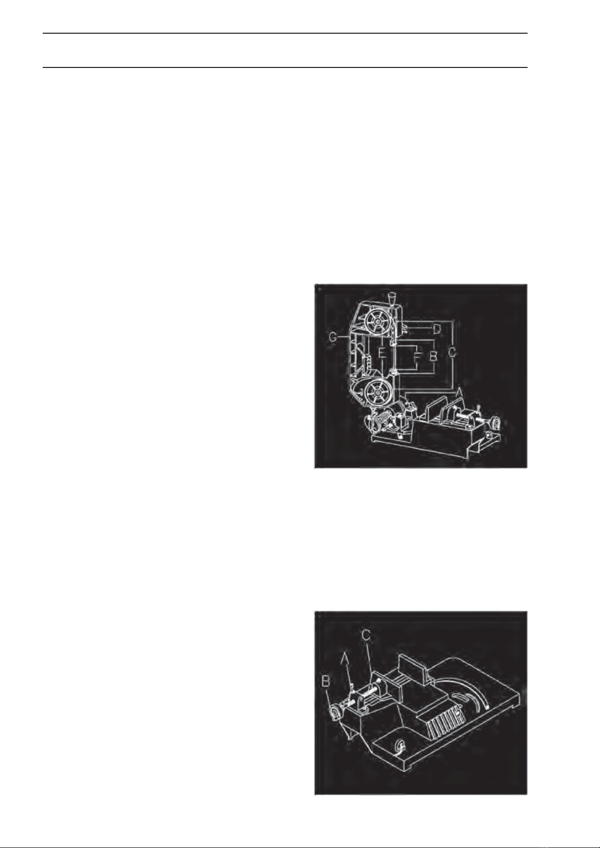
1. Maschine vom Stromnetz trennen.
2. Die Sägebandabdeckung und das Sägeband
entfernen.
3. Die Radschraube (A) Fig. 8 entferen.
4. Das Bandrad entfernen und das Zahnrad mit
einem zähflüssigem hochwertigem Fett (BLASO-
LUBE 304 oder ähnliches) schmieren.
5. Bandrad wieder montieren und die Radschraube
(A) festziehen.
6. Alle Abdeckungen und Schutzvorrichtungen wie-
der montieren.
10
AUSSERORDENTLICHE WARTUNG
Die ausserordentliche Wartungen sind von Fachperso-
nal durchführen zu lassen. Es empfiehlt sich auf jedem
Fall, sich an Ihren Maschinen-händler zu wenden.
Als ausserordentliche Wartung ist auch die
Wiederherstellung der Schutzabdeckungen und Si-
cherheitsvorrichtungen anzusehen.
AUSSERBETRIEBSETZUNG
Wenn die Sägemaschine längere Zeit nicht ver-
wendet wird, empfiehlt es sich
-den elektrischen Netzstecker zu ziehen.
-den Kühlmittelbehälter zu leeren.
-die Maschine sorgfältig zu reinigen und ausrei-
chend zu konservieren.
-falls erforderlich, die Maschine mit einer Plane
zudecken.
ENTSORGUNG
Allgemeine Vorschriften
Bei der endgültigen Abrüstung und Verschrottung
der Maschine muss derArt und der Zusammenset-
zung der zu entsorgenden Materialien Rechnung
getragen werden. Dies bedeutet im Einzelnen:
-Eisenhaltige Materialien und Gusseisen, die
allerdings immer nur aus Metall bestehen, bei
welchem es sich um einen sekundären Rohstoff
handelt, müssen, vorbehaltlich der Vergütung der
enthaltenen Bestandteile, den zur Einschmelzung
ermächtigten Eisenwerken übergeben werden.
-Die elektrischen Bestandteile, einschliesslich
Netzkabel und elektronisches Material, welches
als dem städtischen Müll assimilierbar eingestuft
wird,kann direkt der Verwaltung der Müllabfuhr,
übergeben werden.
-für die gebrauchte Mineral-, synthetischen oder
gemischten Oele, wasserlöslichen Oele und Fet-
te, bei welchen es sich um Spezialmüll handelt,
muss man sich zwecks Lagerung, Transport und
anschliessender Entsorgung an das Konsortium
für Gebrauchtöle wenden.
Fig. 8

Safety Information
Like any machine, a metal band saw has the dangers that are inherent in the use and handling of machines
in general. Careful start up and correct handling significantly reduce accident hazards. On the other hand,
neglect of basic precautions will inevitably involve accident hazards for the operator.
This machine is specifically designed for its recommended use. For this reason we strongly advise against
any use for operations not envisaged by the manufacturer and any modification of the machine.
If you have any questions about its use and if you cannot find the answer in this manual, please consult your
distributor who will give you professional assistance.
GENERAL GUIDELINES ON THE SAFETY AND HANDLING OF THE MACHINES
1. For your own safety never start a machine before having studied the instruction manual. It helps you get to
know the machine and how to handle it, familiarises you with its possibilities and its limits of operation and
informs you of hazards encountered because of negligence.
2. Keep the guards in perfect working order, do not disassemble them.
3. Plug electrical machines, fitted with an earthed mains plug, into a socket which is earthed. Where
adapters that are not earthed are used, connect the earth terminal of the machine directly. Never start up
a machine if it is not earthed.
4. Before starting the machine, remove all keys or operating levers that are not an integral part of the
machine. Get into the habit of checking that there are no unattached parts in the vicinity of moving
components.
5. Clear sufficient workspace around the machine. Cluttering of work benches or manoeuvring zones
inevitably causes accidents.
6. Do not use the machine in a hazardous environment. Do not operate electrical machinery in wet areas:
do not expose them to rain. Ensure that the work bench and the operator’s phase development area are
well lit.
7. Keep children and visitors away from the machine and ensure that they keep a safe distance from the
work area.
8. Protect the work area from unauthorised access. Have locks put on doors or a lock put on the main
switch in order to avoid children starting it.
9. Ensure that the machine is not working at overload. Performance is better and the machine is used more
safely if it is operating within its capacity limits.
10. Do not use the machine for work other than that for which it was designed.
11.Wearappropriateworkclothes.Avoidlooseclothing,gloves,scarves,rings,chainsandnecklacesorotherjewellerythatcould
getcaughtinmovingparts.Wearnon-slipfootwear.Wearheadwearthatcompletelycontainslonghair.
12. Always wear protective goggles and, if necessary, a dust mask. Observe guidelines for the
prevention of accidents at work.
13. Always clamp the part to be worked on in a vice or a fastening device. Holding it by hand is hazardous
and it is preferable that both hands remain free to operate the machine.
14. Adopt a physically stable position (position of feet, body balanced).
15. Maintain the machine in good condition. Keep the cutting edges clean and well sharpened in order to
exploit the machine’s total capacity. Observe the cleaning, lubrication and tool replacement sections of
the instruction manual
.11

Safety Information
16. Unplug the mains plug before performing maintenance or replacing items such as the saw blade, drill
bits and cutting tools etc.
17. Use only the recommended accessories and follow the instructions given to this end in the manual.
Using an accessory from a different system will involve accident hazards.
18. Avoid accidental starting. Before each mains connection, always check that the switch on the machine is
turned to the OFF (AUS) position.
19. Never climb onto the machine. Tilting it or coming into contact with the cutting tool can cause very
serious accidents.
20. Control the machine’s defective components. Protective components or damaged parts must be correctly
repaired or replaced before work is continued.
21. Never leave a machine operating on its own. Always switch off the mains power supply and do not leave
the machine until it has completely stopped.
22. Never operate a machine under the influence of alcohol, certain medications or drugs.
23. Make sure the power is off before working on electrical components, the drive motor etc.
Work safety instructions
Transportationofthemachine
1. The machine weighs 23kg.
2. Use the appropriate means of transportation to transport the machine.
Work station
1. There should be sufficient lighting and ventilation for the work area.
2. The lighting should be at a level of 300 LUX to guarantee proper work.
Noise level
In compliance with point 1.7.4f of the EC Machines Directive 89/392 four measurements were made of the
machine operating in the unloaded condition.
- The microphone was placed near the head of an average size operator.
- The machine operating in its unloaded state emits noise levels below 70 dB
- The maximum level of C WEIGHTED instantaneous sound pressure has always been less than 130 dB.
N.B.: with the machine running, the noise level will vary depending on the materials being machined.
Consequently, the user should appreciate its intensity and, where necessary, provide staff with the appropriate
ear protection helmets, under the terms of Legislative Decree 277/1991 original version.
Electrical connection
1. The model 348C machine comes with power cable and 230V, 50Hz plug.
2. Fuses must be at least 10A.
3. The exact specifications are on the nameplate of the machine and the electrical diagram attached to these
instructions.
4. ATTENTION: Unplug the machine from the mains (remove the plug) for any technical assistance or
conversion operations as well as for repairs to the machine.
5. The yellow/green earth wire is important for electrical safety. It should therefore be assembled correctly.
12

Special safety rules for the saw
WARNING: For your safety, only use your metal hacksaw after having fully assembled and installed it
according to the instruction manual... and after having read and understood perfectly the instructions below.
Before using the saw:
1. Assembly and adjustment:
Understand the operation and proper use:
a. Of the stop-start switch.
b. Of the top and bottom blade guards.
c. Of the shaft lock and locking handle.
d. The oblique clamping jaws, guide-stops and the metal locking handle
2. Read and understand all safety and operating instructions in the instruction manual.
3. Read the warning labels on the metal hacksaw.
Before each use :
1. Inspect your saw. If any part whatsoever of the saw is missing, bent or defective, or if any electrical
components are not working correctly, stop the saw and unplug it. Replace damaged, missing or
defective parts before using the saw again.
2. Organise your work in order to protect your eyes, hands, face and ears.
a. Wear protective eyewear (not glasses) that are compliant with standard DIN 58214 (shown on the
packaging). The use of an electric power tool can result in the projection of foreign objects into the eyes
and a risk of permanent eye damage. You can purchase protective eyewear in tool shops. The use of
glasses or "work" goggles not in compliance with standard DIN 58214 may result in serious injury through
breakage of the eye protection.
b.For operations which create dust, wear a face shield as well as protective eyewear.
c. To avoid injury in the event of a section jamming, slipping or being projected outwards:
1. It is imperative to choose a blade suited to the material and type of cut planned. The saw is equipped
with a bimetallic blade which can be used for cutting stainless steel, steel, iron, brass, aluminium, wood,
plastic, etc.
2. Make sure that the arrow on the blade showing which way round it should be matches up with the one
on the saw. The blade teeth should always be pointing downwards, at the front of the saw.
3. Make sure that the blade is sharp, in good condition and properly aligned. After unplugging the saw,
push the cutting head right back down again. Run the blade through by hand and check on the play. Tilt
the cutting head at an angle of 45 degrees and check again. If the blade hits something, make the
adjustments shown in the "maximum cutting capacity maintenance” paragraph.
4. Make sure the blade and shaft collars are clean.
5. Make sure that all the locks and fasteners are tight and no parts have excessive play.
Never make a cut BY HAND:
a. Firmly press the workpiece against the guide-stop and the surface of the table so that it does not rock or
rotate during cutting. Check that no debris is stuck under the part.
b. Make sure that there are no gaps between the workpiece, the guide-stop and the table, liable to allow the
part to fly out after it has been cut in two.
c. Use mounts, fasteners and other tools for unstable parts.
Never cut more than one piece at a time.
Make sure that the part can move sideways after being cut. Otherwise it may get jammed against the
blade and be thrown out violently.
Make sure that other people nearby are clear of the tool and workpiece. Keep them outside of the debris
projection area, behind the saw.
Never start the metal hacksaw before having completely cleared the table, except for the part and its
fastening devices. 13

Special safety rules for the saw
d. To avoid the risk of hearing damage, wear earplugs or hearing protection during extended periods of use.
e. To avoid getting suddenly caught up by the blade
1. Do not wear gloves.
2.Take off any jewellery and loose clothing.
3.Completely contain long hair.
4.Roll up long sleeves to above the elbow.
f. To avoid being injured by an accidental start, always unplug the saw before removing the guard,
assembling or disassembling the blade or an accessory, or making any adjustments whatsoever.
g. To avoid electric shock, do not touch the metal pins of the plug when connecting or disconnecting to the
mains socket.
h. Never lubricate the blade while it is operating.
i. To avoid burns and fire hazard, never use the saw near flammable liquids, vapours or gas.
j. To avoid being injured by any hazardous accessories, use only accessories appearing in this manual’s list
of recommended accessories.
When the saw is operating
WARNING: Do not allow yourself to become negligent through force of habit (because of frequent use of
your saw). Never forget that a split second of inattention is enough to cause serious injury.
1. Before making the cut, let the saw run for a time. If your saw makes unusual noises or vibrates
excessively, stop it immediately. Turn the saw off Unplug it. Do not restart it until the problem has been
located and been remedied.
2. Never hold on to the blank. You should never hold on to it, lock it, touch it or use the longitudinal stops for
it. It must be free to move sideways. If it is held it may get jammed against the blade and be thrown out
violently.
3. Avoid any awkward positioning of the hands risking getting them caught up in the blade in case of a
sudden slip.
4. Let the blade reach its maximum speed before making the cut.
5. Move the saw forwards into the part at a speed that is exactly enough to allow the blade to cut without
getting bogged down or stuck.
6. Before freeing a part that is jammed, release the trigger and unplug the saw. Wait until all the moving
parts are stationary.
7. After having completed the cut, hold the cutting head in the low position, release the trigger and wait for
all the moving parts to come to a standstill before moving your hands.
WARNING! Read the warning labels below
that are positioned on the front of the saw.
DANGER
Tighten the shaft screw and all the
fasteners before turning the saw on.
14
DANGER
Keep hands away from the path of the
blade.
Never cut anything by hand.
Do not place your hand behind or under the
blade
To avoid electric shock, do not expose the
saw to rain.

Power supply
Engine Specifications
The direct current motor used on this saw is a non-
reversible induction motor with the following
specifications:
Maximum power (kW) 0.38
Voltage (V) 230
Amps (A) 4
Frequency (Hz) 50
Revs (rpm) 1,430
Speed of the blade (m/min) 45
Direction of rotation of the blade drive
shaft to the right
Weight (kg) 23
Earthing
This metal hacksaw is a single-insulated tool, the
earthing circuit therefore being designed to protect you
from electrical shocks. The earthing circuit is made once
you have connected the machine to the appropriate
mains power supply. You should therefore provide a
mains power system for this machine that protects you
from electric shock hazard.
Protecting the motor
WARNING:
To prevent any electrical hazard, fire hazard or
damage to the tool, use the appropriate circuit
protection device. Your saw is wired at the
factory to run on 230 V current. Connect it to 10
Amp 230 V mains power supply and use a 10
Amp time delay fuse or circuit breaker. To
prevent electric shock or fire, immediately
replace the power supply cable if it is worn, cut
or damaged in any other way.
DANGER
To prevent electric shock:
1. Only replace the power supply cable and plug
with identical models supplied by the
manufacturer.
2. Do not use the saw in rain or on wet ground.
This tool is only intended for home use,
indoors.
1. Connect this tool to a 10 A, 230 V power supply circuit with a 10 A time delay fuse or circuit breaker.
The use of a fuse with the incorrect amperage could damage the motor.
2. If the motor does not start, immediately release the trigger. UNPLUG THE TOOL. Check the the blade runs
freely. If this is the case try to start the motor again. If the motor still does not start, refer to the “Motor
Troubleshooting table"
3. If the motor suddenly locks when cutting wood, release the trigger, unplug the tool and remove the blade from
the wood. Then try to restart the motor and finish the cut.
4. The fuse may "melt" or the circuit breaker trip if:
a. The motor is overloaded - there is overload hazard in cases of too rapid advancement, or of stopping and
starting too frequently in a short period of time.
b. A voltage up to 10% maximum higher or lower than that indicated on the nameplate can withstand normal
loads. In case of heavy loads, however, the voltage (due to a wire whose gauge is too small or one that is
too long in the power supply circuit) may fall to the point of not allowing the motor to function. Always
check the connections, the load and the power supply circuit if the motor malfunctions. Check the wire
gauges and lengths in the Wire gauge table below.
5. Most problems with the motor can be attributed to incorrect or loose connections, overload, insufficient voltage
(due, for example, to a wire with too small a gauge in the power supply circuit) or a wire that is too long in the
power supply circuit. Always check the connections, the load and the power supply circuit if the motor
malfunctions. Check the wire gauges and lengths in the Wire gauge table below.
Wire gauges
Use of an extension lead results in a loss of power. To minimise and avoid overheating and motor breakdown of
the motor determine the minimum gauge (the cross section) of the extension lead wires using the table below. For
circuits more than 40 m away from the power supply cabinet, the gauge of the wires should be proportionately
increased, in order to deliver sufficient voltage to the saw motor.
Cable Length Wire gauge recommended for 230V.
Up to 15 m 1,5 mm²
15 to 40 m 2,5 mm²
15

Specifications
Band motor ............. 230V, 0.38kW, 4A
Dimensions of the band ....... 1470 x 13 x 0.65mm
Speed of the band ............ 45m/min.
Dimensions L/W/H .... 720 x 390 x 460mm
Weight .............................. 23 kg
Cutting capacities mm
90°
round
rectangular
45 ° round
rectangular
100
100x150
60
60x90
Description and features
1. This portable 100mm metal band saw weighs only 23 kg and is equipped with a handle allowing you to
carry it easily from one workplace to another.
2. The machine body is made of die-cast aluminium (moulded aluminium optional), to give it more strength
and a smoother and more attractive appearance.
3. In use the noise level of this machine is about 60 dB, and therefore much lower than that of any other
metal band saw, thereby ensuring a comfortable working environment.
4. This machine allows the blade tension to be adjusted, by slightly turning the handle so as to increase or
reduce the tension, according to need, when replacing the blade or using the machine. A pair of
compression springs fixed to the handle reduce vibration caused by jolts from a defective part when the
machine is functioning. This measure greatly extends the life of the blade.
5. The drive is effected via a gear transmission which ensures more regular, more powerful and smoother
cutting, which is better than those of all the pulley drive band saws and reduces after-sale problems.
Note :
If you discover a problem with your gear transmission system, do not try to repair it yourself. Send it back
to your supplier for it to be checked over and repaired, in case you damage the machine.
6. The machine allows for horizontal cutting, vertical cutting and mitre cutting, and its design ensures
maximum output and comfort of the operator in all positions.
7. The automatic stop ensures complete execution of the cut, thereby allowing unattended operation.
Quick vice and installing the part
BEFORE MAKING A CUT
Loosen the locking tab (A) of Fig. 1 to release the saw.
After use, replace the locking tab and tighten it properly
to ensure your safety during transport. Any failure to
comply with this warning could result in personal injury
and damage to the machine.
Using the quick vice
The machine is equipped with a new improved
“quick” vice.
Three components and a lever allow for simple
resolution of all the problems met before. Perform
the simple operations described below. You will
appreciate the convenience of our device.

Quick vice and installing the part
1. Lift the lever (A) in Fig. 2 to be able to move the vice
easily back and forth, using the wheel (B) at the left
side of the base.
2. Push the clamping jaw (C) towards the part, by moving
it as much as possible towards the other clamping jaw,
which is fixed.
3. Fold the lever back down.
4. Turn the wheel (B) in a clockwise direction to ensure
good positioning of the part. In using it you will find that
this method of fastening the part is more practical and
effective than all the traditional systems.
Installing the part
1. Raise the head of the saw until it is vertical.
2. Open the vice so as to be able to introduce the part to be cut by pulling on the wheel at the end of the
base.
3. Place the part on the saw bench. If it is long, support the end of it.
Unpacking and checking the contents
The metal hacksaw comes complete in a box. Remove all
packaging materials from the parts and check the different items
according to the illustration and "Table of accessories”. Make
sure that all the items are present before throwing away the
packaging materials.
WARNING : If any parts whatsoever are missing, do not try to
assemble the saw, plug in the power cable or press the trigger,
before having recovered the missing part and having mounted
it correctly.
Pos.
Description
Qty
A
Basic Saw
1
B
Stop pin
1
C
Blade guard
1
D
Instruction manual
1
Tools required for installation
Note : The tools illustrated are not supplied with the saw.
Toolbox
Fix the tool box to the frame with 2 screws and you will always
have your tools handy.
17

Use
Before use
Make sure the blade is not in contact with the part when the motor is started.
Run the motor and let the saw reach full speed. Start the cut by bringing the head down slowly over the part.
DO NOT LOWER THE HEAD BACK DOWN AND DO NOT FORCE IT. Allow the weight of the saw to make
the effort required for the cutting. The saw will automatically stop at the end of the cut.
Feed rate
The feed rate is pre-set (mark H) in the factory for full
metal cutting.
To reduce the feed rate, proceed as follows:
1. Release the locking pin by gently pulling on button
(A) of Fig. 3.
2. Turn wheel (B) towards the button and stop at mark
M. Let the locking pin slide into the groove. The
feed rate is adjusted for cutting thicker metal tubing.
3. Turn the wheel, stop at mark L and lock it at this
position. The feed rate is adjusted for cutting thinner
metal tubing.
Oblique cut
The machine uses a pivoting mitre block for oblique cuts
from 0 to 45 degrees. The pivot arm has an an index -
(A) in Fig. 4. The machine is pre-set to zero degrees
when it leaves the factory. An oblique cut is adjusted in
the following way:
1. Loosen bolt (B) to release the arm.
2. Move the pivot arm forwards along the scale to find
the angle that best fits the part to be cut.
3. If the index corresponds to the appropriate
gradation of degrees on the the scale, tighten the
bolt. This will ensure cutting at the perfect angle.
Fig. 3
Fig. 4
Direction of travel of the blade
Make sure that the blade is mounted on the wheels in such a way that the vertical cutting edge engages first
with the part.
BEFORE STARTING THE SAW
DO NOT FORGET TO DETACH THE LOCKING TAB BETWEEN THE ARM OF THE SAW AND THE SAW
BENCH TO RELEASE THE SAW. AFTER USE DO NOT FORGET TO REPLACE IT TO PERMIT EASY
AND SAFE TRANSPORTATION OF THE MACHINE.
18

Use
WARNING
Disconnect the machine from the power supply!
The saw requires constant vigilance, whether during transportation, use, maintenance or making
adjustments. Any breach of this rule may result in serious injury!
Replacing the blade
1. Raise the cutting head by 90 degrees by gently lifting
button (A) of Fig. 5 so as to release the locking pin
and slide it into the groove to allow the saw arm to be
positioned in the vertical position.
2. Remove the blade guards (B) and the blade cover by
undoing the two bolts (C) of the saw casing.
3. Push back the tension lever (D) to the left to allow the
blade to be released.
4. Remove the blade from the two wheels (E) and the
blade guide bearings.
5. Place a new blade on the edges of the wheels. But
without tightening it too much, twist the blade slightly
and slide it between the two guide bearings. Make
sure that the blade teeth are oriented downwards
(towards the saw bench).
Fig. 5
6. Tighten the tension lever by turning it to the right. Run the blade through by pulling it downwards with one
hand. It will align itself properly on the wheels.
7. Replace the blade guards and cover (G) Start the machine to check if the blade is functioning properly.
Vertical cut
1. Fix the support bar (A) of Fig. 6 into the groove of
the cutting head.
2. Raise the head of the saw to the vertical position by
lifting button (B) slightly to release the locking pin
and slide it into the groove allowing it to be
positioned at 90 degrees.
3. Remove the little plate (C).
4. To be able to cut a large piece, remove the carrying
handle (E). After use, put the handle back in place.
Magnetic switch
The metal band saw is equipped with a TRIPUS magnetic
switch intended to ensure safe use. In case of power failure,
the machine cannot be started again except by opening the
lid and pressing the "ON" button inside. A red button is
mounted on the switch cover. In case of emergency press it
to stop all the machine functions. This magnetic switch is also
connected to the positional switch located at the back of the
saw bench; when the part is completely cut, both switches cut
out automatically.
Fig. 6
Red green
STOP GO 19

Settings
Blade guide settings
The machine has a freely moving lever to alter the
direction by lifting and turning it slightly. It allows you
quickly and easily to adjust the blade guide at any time.
The blade guide is adjusted in accordance with the
dimensions of the parts. Only the one on the left of the
cutting head can be adjusted; the other is fixed.
1. If the part is large, undo lever (A) of Fig. 7. Move the
guide by about 2.5 cm towards the part, then tighten
the lever again.
2. If you are cutting a small part bring the guide as
close as possible to the part. The two types of cut
will guarantee satisfactory accomplishment of the
work.
Adjustment where there is poor
cutting
The machine has been adjusted and subjected to
different cutting tests before leaving the factory to
ensure that it functions properly. If you discover that it is
cutting poorly, correct the defect by doing the following:
1. Poor cutting due to blade wear: put in a new blade.
2. The saw is equipped with fixed ball bearings.
To ensure correct cutting, we recommend to replace
them every three or six months, depending on the
frequency of use.
3. Poor cutting can be due to loosening of the
fastening nut (A). Tighten it again correctly.
Fig. 7
WARNING
Do not make any adjustment and do not load
or unload the part from the vice when the
machine is operating!
Bearing
Maintenance of the gear transmission
The gears of the transmission system fitted to the
machine are made of special steel.
The quality of these gears gives them superior strength
and durability. To keep the saw operating optimally, we
advise you to lubricate them every three months by
carrying out the following procedure:
1. Undo the screw (A) of Fig. 8 using an 8 mm Allen key.
2. Remove the wheel (B), then lubricate the gears
using thermostable grease.
3. Carefully re-assemble the wheel, and tighten the
screw correctly (A). Fig. 8
Adjusting blade tension
The tensioning system of the machine is designed to facilitate interventions. It is sufficient to turn control lever
(B) of Fig. 6 to increase or reduce the tension of the blade as needed, during operation. The main function of
this adjustment is to ensure perfect cutting as it allows the blade to work at a constant tension. A pair of
compression springs fastened to the tensioning system are there in addition to reduce the play of the blade.
All this contributes to prolonging the lifetime of the latter.
Table of contents
Languages:
Other Promac Saw manuals

Promac
Promac SY-350-ALU Service manual

Promac
Promac MBS-56CS-M User manual

Promac
Promac 347V Service manual

Promac
Promac SX-815DVP User manual

Promac
Promac VBS-1610 Service manual

Promac
Promac SX-818DV User manual

Promac
Promac SX-821DA User manual

Promac
Promac MBS-910CS User manual

Promac
Promac SX-823DGSVI User manual

Promac
Promac MCS-275 User manual