8
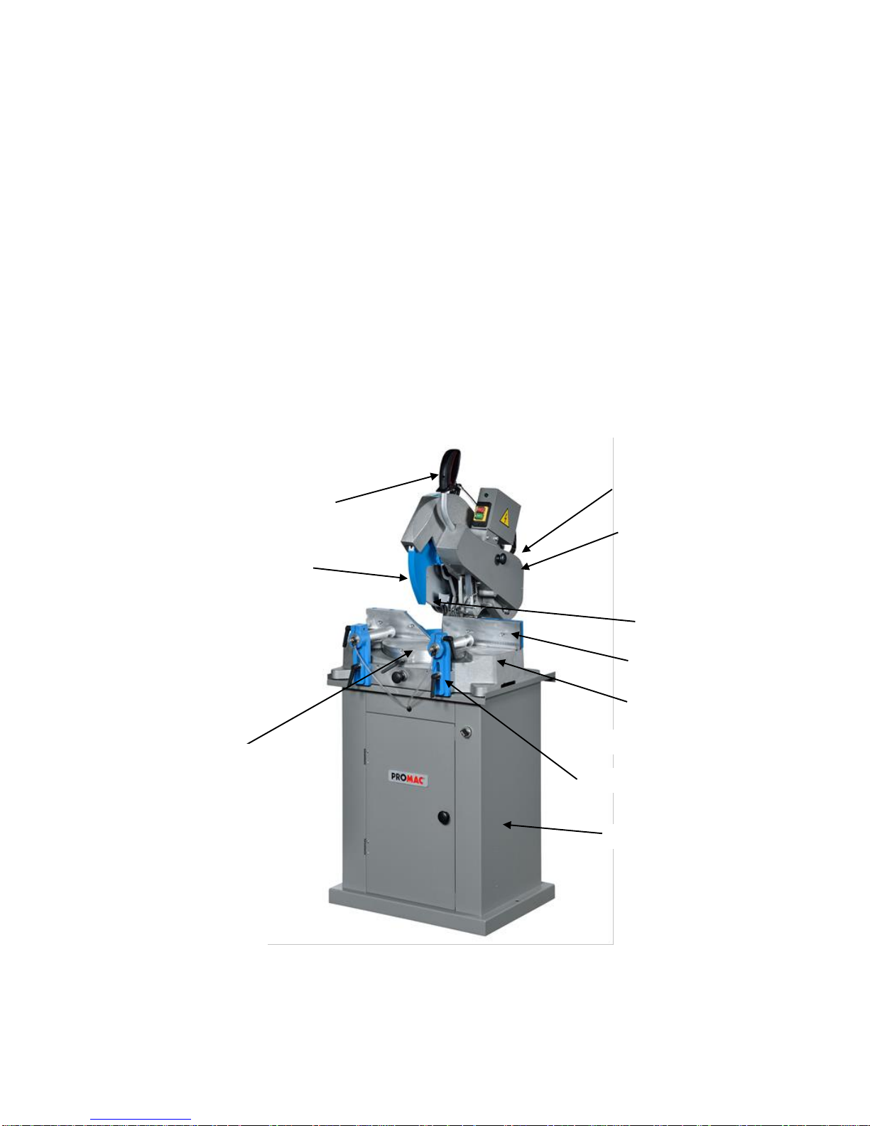
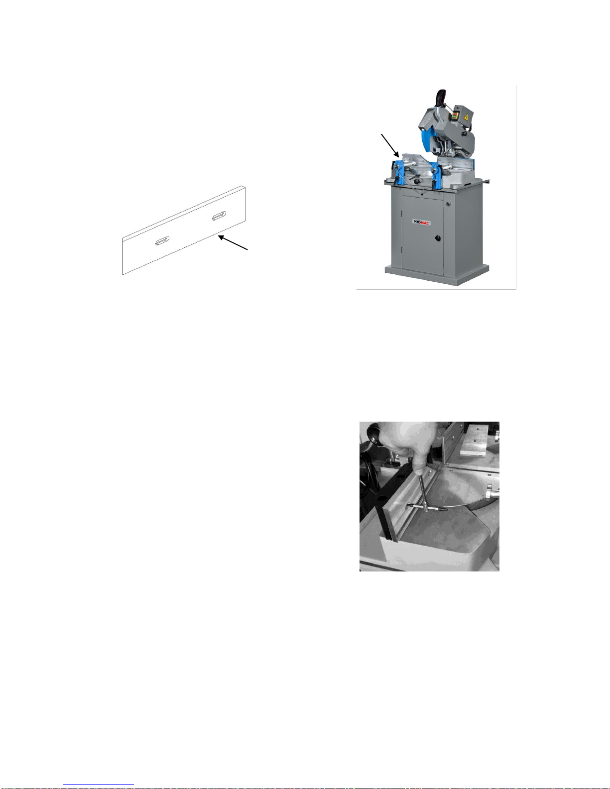
Controls and Indicators
Keep this manual in a good state and
available at a close distance from the
machine.
Foreword
For the preparation of this manual, we
have considered all operations referring
to normal use and regular maintenance
of the machine. Therefore, for correct
and optimal use of the machine, it is
necessary to carefully follow the
instructions described herein. The use
of the machine should be entrusted only
to authorized and skilled personnel.
Attention: It is recommended not to
carry out any repair or intervention
unless not indicated. All operations
requiring the disassembly of machine
parts should be entrusted to specialized
technical personnel.
Warranty
The machine is guaranteed for a period
of 24 months starting from the date of
the purchase invoice. It consists of a
free of charge replacement of all
mechanical parts showing material or
manufacturing defects.
All electric and electronic components
are excluded from this warranty. The
warranty does not cover breakages or
defects arising out of external factors,
maintenance mistakes or other causes,
improper use of the machine, use of the
machine overloaded, normal wear,
assembly mistakes which we may not
be held responsible for. Replacements
are shipped ex our factory. The machine
must be returned on a free port basis,
even when covered by the warranty.
Communication
For any written or verbal communication
with the Dealer or with the Firm about
the machine, it is necessary to supply
the following information:
Machine model
Serial number
Voltage & frequency of the machine
Name of the dealer from which the
machine was purchased.
Description of the defect found, if any
description of the type of operation
carried out working hours per day.
Machine identification
The machine model is identified by a
plate situated at the front of the base,
showing the following data:
Serial number
Year of manufacture
Manufacturer’s name
Use and limitations to use
The machine is for professional use and
has been designed and conceived for
cutting wooden semi-finished materials
and their sub-products and, with suitable
adaptations (a suitable blade and a
“vise” accessory plastic materials (PVC)
or light alloys (aluminum).The protection
rating of the electrical installation is IP
54. Only the user may be held
responsible for any damage arising out
of a different use of the machine other
than that indicates.
Attention:
1. In particular, the machine is not
suitable for cutting ferrous materials.
2. The machine cannot be used in
explosive environments.
Expected machine life
The expected life of the machine under
conditions of normal use and regular
maintenance is to be considered of at
least 5 years.
Machine disposal
When the machine is no longer
operative, it can be disposed of by
means of a standard disposal center for
industrial wastes, as it is classified as
standard solid waste material.