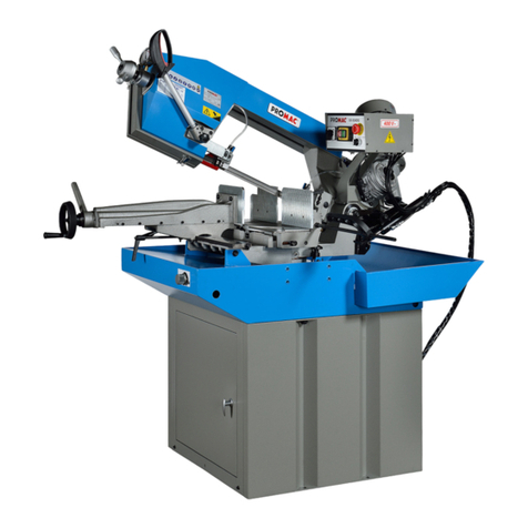
Promac SX-823DGB User manual

2
CE-Conformity Declaration CE-
Konformitätserklärung
Déclaration de Conformité CE
Product / Produkt / Produit:
Metal band saw
Metallbandsäge
Scie à ruban portable
SX-823DGB
Brand / Marke / Marque:
PROMAC
Manufacturer / Hersteller / Fabricant:
JPW (Tool) AG, Tämperlistrasse 5, CH-8117 Fällanden
Schweiz / Suisse / Switzerland
We hereby declare that this product complies with the regulations
Wir erklären hiermit, dass dieses Produkt der folgenden Richtlinie entspricht
Par la présente, nous déclarons que ce produit correspond aux directives suivantes
2006/42/EC
Machinery Directive
Maschinenrichtlinie
Directive Machines
2014/30/EU
electromagnetic compatibility
elektromagnetische Verträglichkeit
compatibilité électromagnétique
designed in consideration of the standards
und entsprechend folgender zusätzlicher Normen entwickelt wurde
et été développé dans le respect des normes complémentaires suivantes
EN ISO 12100:2010
EN 13898:2003+A1:2009
EN 60204-1:2006+A1:2009
EN 61000-6-2:2005
EN 61000-6-4:2007+A1:2011
Responsible for the Documentation / Dokumentations-Verantwortung / Résponsabilité de Documentation:
Hansjörg Meier
Head Product-Mgmt. / Leiter Produkt-Mgmt. / Resp. Gestion des Produits
JPW (Tool) AG
2017-10-13 Jan Dätwyler, General Manager
JPW (Tool) AG, Tämperlistrasse 5, CH-8117 Fällanden
Schweiz / Suisse / Switzerland

3
△
!
CAUTION
Install saw blade and blade guard
before use. Set proper blade tension to prevent
any danger caused by damaged saw blade or work
piece.
△
! ACHTUNG
Vor dem Gebrauch das Sägeblatt und die
Sägeblattabdeckung installieren. Korrekte
Blattspannung einstellen, um zu verhindern, dass
keine Gefahr durch beschädigtes Sägeblatt oder
Werkstück auftritt.
△
! ATTENTION
Installer la lame de scie et la garde de lame
Avant utilisation Régler la tension correcte de la
lame pour éviter tout danger causé par
une lame de scie endommagée ou une pièce à
travailler.

4
EN –ENGLISH
1. Overall Aspect
The blade tension
handle
Lift handle (w/o switch)
Saw arm
Control Panel
Move Vise
Motor
The move vise handle
Angle Sale
Visebase
Base
The swivel vise
base of handle
Stand

5
WARNING: FAILURE TO FOLLOW THESE RULES MAY
RESULT IN SERIOUS PERSONAL INJURY
As with all machinery there are certain hazards involved with operation and use of the machine. Using the machine
with respect and caution will considerably lessen the possibility of personal injury. However, if normal safety
precautions are overlooked or ignored, personal injury to the operator may result.
This machine was designed for certain applications only. We strongly recommend that this machine NOT be modified
and/or used for any application other than for which it was designed. If you have any questions relative to its application
DO NOT use the machine until you contact with us and we have advised you.
Your machine might not come with a power socket or plug. Before using this machine, please do ask your local
dealer to install the socket or plug on the power cable end.
2. SAFETY RULES FOR ALL TOOLS
A.
USER:
(1).
WEAR PROPER APPAREL. No loose clothing, gloves, rings, bracelets, or other jewelry to get caught in
moving parts.
Non-slip footwear is recommended. Wear protective hair covering to contain long hair.
(2).
ALWAYS WEAR EYE PROTECTION. Refer to ANSLZ87.1 standard for appropriaterecommendations. Also
use face or dust mask if cutting operation is dusty.
(3).
DON'T OVERREACH. Keep proper footing and balance at all times.
(4).
NEVER STAND ON TOOL. Serious injury could occur if the tool is tipped or if the cutting tool is accidentally
contacted.
(5).
NEVER LEAVE TOOL RUNNING UNATTENDED. TURN POWER OFF. Don't leave tool until it comesto a complete
stop.
(6).
DRUGS, ALCOHOL, MEDICATION. Do not operate tool while under the influence of drug, alcohol or any
medication.
(7).
MAKE SURE TOOL IS DISCONNECTED FROM POWER SUPPLY. While motor is being mounted, connected
or reconnected.
(8).
ALWAYS keep hands and fingers away from the blade.
(9). STOP the machine before removing chips.
(10). SHUT- OFF power and clean the BAND SAW and work area before leaving the machine.
(11).DO NOT Touch the cutting Blade while the machine is turm on.
B.
USE OF MACHINE:
(1).
REMOVE ADJUSTING KEYS AND WRENCHES. Form habit of checking to see that keys and adjusting
wrenches are removed from tool before turning it "on".
(2).
DON'T FORCE TOOL. It will do the job better and be safer at the rate for which it wasdesigned.
(3). USE RIGHT TOOL. Don't force tool or attachment to do a job for which it was notdesigned.
(4).
SECURE WORK. Use clamps or a vise to hold work when practical. It's safer than using your hand frees both
hands to operate tool.
(5).
MAINTAIN TOOLS IN TOP CONDITION. Keep tools sharp and clean for best and safest performance.
Follow instructions for lubricating and changing accessories.
(6).
USE RECOMMENDED ACCESSORIES. Consult the owner's manual for recommended accessories. Theuse of
improper accessories may cause hazards.
(7).
AVOID ACCIDENTAL STARTING. Make sure switch is in “OFF” position before plugging in power cord. (8).
DIRECTIONOF FEED. Feed work into a blade or cutter against the direction of rotation of the blade or cutter only.
(9).
ADJUST AND POSITION the blade guide arm before starting the cut.
(10).
KEEP BLADE GUIDE ARM TIGHT, A loose blade guide arm will affect sawing accuracy. (11).
MAKE SURE blade speed is set correctly for material being cut.
(12).
CHECK for proper blade size and type.
(13).
STOP the machine before putting material in the vise.
(14).
ALWAYS have stock firmly clamped in vise before starting cut.
(15).
GROUNDALL TOOLS. If tool is equipped with three-prong plug, it should be plugged into a three-hole electrical
receptacle. If an adapter is used to accommodate atwoprong receptacle, the adapter lug must be attached to a
known ground. Never removed the third prong.
C.
ADJUSTMENT :
6
MAKE all adjustments with the power off. In order to obtain the machine. precision and correct ways of adjustment
while assembling, the user should read the detailed instruction in this manual.
D.
WORKING ENVIRONMENT:
(1).
KEEP WORK AREA CLEAN. Cluttered areas and benches invite accidents.
(2).
DON'T USE IN DANGEROUS ENVIRONMENT. Don't use power tools in damp or wet locations, or expose them
to rain. Keep work area well-lighted.
(3).
KEEP CHILEREN AND VISITIORS AWAY. All children and visitors should be kept a safe distancefrom work area.
(4).
DON’T install & use this machine in explosive, dangerousenvironment.
E.
MAINTENANCE:
(1).
DISCONNECT machine from power source when makingrepairs.
(2).
CHECK DAMAGED PARTS. Before further using of the tool, a guard or other part that is damaged should be
carefully checked to ensure that it will operate properly and perform its intended function. Check for alignment of
moving parts, binding of moving parts, breakage of parts, mounting, and any other conditions that may affect its
operation. A guard or other part that is damaged should be properly repaired or replaced.
(3).
DISCONNECT TOOLS before servicing and when changing accessories such as blades, bits, cutters, etc. (4).
MAKE SURE that blade tension and blade tacking are properly adjusted.
(5).
RE-CHECK blade tension after initial cut with a new blade.
(6).
TO RPOLONG BLADE LIFE ALWAYS release blade tension at the end of each workday.
(7).
CHECK COOLANT DAILY Low coolant level can cause foaming and high blade temperatures. Dirty coolant can
clog pump, cause crooked. Rust, low cutting rate and permanent blade failure. Dirty coolant can cause the growth
of bacteria with ensuing skin irritation.
(8).
WHEN CUTTING MAGNESIUM NEVER use soluble oils or emulsions(oil-water mix) as water willgreatly
intensify any accidental magnesium chip fire. See your industrial coolant supplier for specific coolant
recommendations when cutting magnesium.
(9).
TO PRNMT corrosion of machined surfaces when a soluble on is used as coolant, pay particular attention to
wiping dry the surfaces where fluid accumulates and does not evaporate quickly, such as between the machine bed
and vise.
F.
SPECTIFIED USAGE:
This machine is used only for general metals cutting within the range of cutting capacity.
G.
NOISE:
A weighted sound pressure level : under80 dB.
H.
SAFETY DEVICE:
Interlock switch on cutting area as soon as the cover of cutting area is open, machine will stop at once witch the
function of this switch. Do not remove this switch from machine for any reason, and check its function
frequently.
3. SPECIFICATION
Variable Speed 23~92(50HZ)/28~110(60HZ)
MOTOR
1.5HP(2-Speed)
Saw Blade Speed
FPM
138/276(60Hz) ;115/230(50Hz)
MPM
42/84(60Hz) ;35/70(50Hz)
Blade Size(mm)
27x0.9x2450
Dimension LxWxH (mm)
1350x700x1326
Packing
N.W / G.W (kgs)
270 / 310
Measuremen
t
1490x790x987

7
Cutting
Capacity
0°
○
(mm)
225
□
(mm)
200 x 200
(mm)
240 x 160
45°
○
(mm)
145
□
(mm)
140 x 140
(mm)
145 x 115
-60°
○
(mm)
90
□
(mm)
85 x 85
(mm)
85 x 100
-45°
○
(mm)
145
□
(mm)
140 x 140
(mm)
145 x 100
4. FEARTURES:
1.
This machine is useful for cutting normal steel, steel pipe, and provides cutting angle at + 60°and +45°by the
swivel head.
2.
A tooth selection chart was provided on the machine for cuttingreference.
3.
Variable speed control gives convenient selection of speeds. (This machine comes with a standard 2-
speed motor. But can be purchased with a variable speed as an option.)
4.
This machine is using manual cutting by pulling down the saw bow by hand. Start(press) button is located
at the handle of the saw bow. Motor stops when button was released.
5.
Stability of the machine, plus working table height is 950 mm, conforming to humanengineering.
6.
The one-inch blade and carbide guide provide better result of the cutting surface and efficiency.
7.
The one-piece casting and one time CNC processing provide better rigidity and precision of the machine.
8.
The one-piece and full coverage blade cover conforms to CE stipulation. Well coolant fluid collection system
provides clean and dry, and safety of the working area.
9.
Chip pan underneath the working table prevents coolant fluid leaking and keep floor dry.
10.
Coolant for cutting,, water : oil = 40 : 1 oil specification.
5. TRANSPORTATATION & INSTALLATION:
5-1.Unpacking
1.
Transportation to desired location before unpacking, please use-lifting jack. (Fig. B)
2.
Transportation after unpacking, please use heavy duty fiber belt to lift up the machine.
Fig, B
ALLWAYS KEEP PROPER FOOTING & BALANCE WHILE MOVING THIS MACHINE.
5-2.TRANSPORTATION OF MACHINE:
As this machine weights 253kgs(556.6lbs) it is recommended that the machine be transported with help of lifting jack.

8
Fig. A
Transportation Recommendation:
1.
Tighten all locks before operation.
2.
Always keep proper footing & balance while moving this machine, and onlyause heavy
dutyof fiber belt to lift the machine as per Fig. A.
3.
TURN
OFF
the
power
before
wiring
&
besure
machine
is
properly
grounded.
Overload & circuit breaker are recommended for safetywiring.
4.
Tighten 4 bolts to baseholes after machine is balanced.
5.
Check carefully if the saw blade is running in counter- clockwise
direction if not, reverse the wiring per circuitdiagram, then repeat
the running test.
6.
Keepmachine always out from sun, dust, wet, or raining area.
5-3.Installation:
(1)
Always Keepproper footing & balance while moving this 253kgs machine. And only
use heavy-duty fiber belt to lift the machine as per Fig. (B).
(2)
Hang the machine up, away from the floor, take away the 4 pads and assemble them
on the auxiliary stand. Fix the machine on the auxiliary stand and lock the connection
nut.
(3)
Finish removing this wooden case/crate from the machine. Unbolt the machine from
the crate bottom.
(4)
Position& tighten 4 bolts into base holes properly after machine in balance.
(5)
Turn off the power before wiring & be sure machine is in proper grounding.
Overload & circuit breaker is recommended for safetywiring.
(6)
Keepmachine always out from sun, dust, wet, raining area.
5-4.CLEAIG & LURICATING
B Fig.B
(1)
Your machine has been coated with a heavy grease to protect it in shipping. This coating should becompletely
removed
before
operate
the
machine.
Commercial
degreaser,
kerosene
or
similar
solvent
may
be
used
to
remove the grease from
the machine, but avoid getting solvent on belts or other rubber parts.
(2)
After cleaning, coat all bright work with a light lubricant. Lubricate all points . with a medium consistency
machine oil.
6.
MINIMUM ROOM SPACE FOR MACHINE OPERATION
1540 mm
610 mm
1420 mm

9
7.
MAKE PROPER TOOTH SELECTION
For maximum cutting efficiency and lowest cost
per cut, it is important to select the blade with the right
number of teeth per inch (TPI) for the material being
cut. The material size and shape dictate tooth selection.
TOOTH
SELECTION
You need to consider:
The width of the cut - That is, the distance in the cut
that each tooth must travel from the point it enters
the work-piece until it leaves the work-piece, and
1.
The shape of the work-piece.
Squares, Rectangles, Flats (Symbol : ■)
Locate the width of cut on the chart.
(Inches on the outer circle and millimeters
on the inner circle.) Select the tooth pitch
on the ring marked with the square shape
which aligns with the width of cut.
EXAMPLE: 6" (150mm) square, use a 2/3
Vari-Tooth.
Round Solids (Symbol :●)
Locate the diameter of your work-piece on
the chart. Select the tooth pitch on the
ring marked with the round shape which
aligns with the size of stock you are cutting.
EXAMPLE: 4" (100mm) round, use a 3/4
Vari-Tooth.
Tubing, Pipe, Structural ( Symbol : O H ^ )
Determine the average width of cut by
dividing the area of the work-piece by the
distance the saw blade must travel to finish
the cut. Locate the average width of cut on
the chart. Select the tooth Ditch on the ring
marked with the tubing and structural
shape, which aligns with the average width
you are cutting.
EXAMPLE: 4"(100mm) outside diameter, 3"(75mm)
inside diameter tubing.
4"(100mm) OD =12.5 sq.ln. (79cm2)
3"(75 mm ) ID = 7.0 sq.ln. (44cm2)
Area= 5.5 sq.ln. (35cm2)
5.5 sq.ln. (35cm2) / 4" (100mm) distance
=1.38(35mm) average width
1.38" (35mm), use a 4/6 Vari-Tooth
NOTE: The band speed and cutting rate
recommendations presented on this chart are
approximations and are to be used as a starting point
for most applications. For
exact sawing parameters' consult your saw blade
supplier.
8.
BI-METAL SPEEDS AND FEEDS
These figures are a guide to cutting 4"(100mm) material
(with a 314 Vari-Tooth) when using a cutting fluid.
Increase Band Speed: 15% When cutting
1/4"(6.4mm) material (l0/l4 Vari-Tooth)
12% When cutting
3/4"(19 mm) material (6/10 Vari-Tooth)
10% When cutting 1-
1/4"(32 mm) material(5/8 Vari-Tooth)
5% When cutting 2-
1/2" (64 mm) material(4/6 Vari-Tooth)
Decrease Band Speed: 12% When cutting 8"(200mm)
material(2/3 Vari-Tooth)
MATERIAL
ALLOY ASTM
NO.
BAND SPEED
FT./MI
N
M/MIN
Copper
Alloy
173,932
314
96
330,365
284
87
623,624
264
81
230,260,272
244
74
280,264,632,655
244
74
101,102,110,122,172
234
71
1751,182,220,510
234
71
625,706,715,934
234
71
630
229
70
811
214
65
Carbon
Steel
1117
339
103
1137
289
88
1141,1144
279
85
1141 HI STRESS
279
85
1030
329
100
Carbon
Steel
1008,1015,1020,1025
319
97
1035
309
94

10
TELLTALE CHIPS
Chipsarethebestindicatorsof correctfeed force.Monitorchipinformationandadjustfeed accordingly.
Thinor powderedchips–increasefeed rateor reducebandspeed.
Burned heavy chips –reduce feed rate and/or band speed.
Curlysilveryandwarmchips–optimumfeed rateandband
speed.
9.
USEOF MAINMACHINEPARTS
9-1.POWER SYSTEMS AND CONTROL PANEL
The electrical rating of your band saw is either with 230 volt-single phase, or 400 volt-3 phase, magnetic control.
Before connecting your machine to an electrical power system, be sure the motor shaft is running in the correct direction.
We recommendthat1.5mm²fused witha 10 amp,dualelement,timelagfuse,to be usedto supplypowerto allmachines
regardless of their electricalrating.
Referto theelectricalwiringdiagramsuppliedwithyourmachineforinstructions
on how to connect saw to power source. Power must be cut off when wheel
cover is openedor duringrepairing.
Please check the moving direction of the blade. If the blade is moving in the wrong direction, please re-connect the wire.
9-2-1. STARTING AND STOPPING MACHINE (cylinder system)
1.
Light (D) will be on when power is connected.
2.
Rising up the saw arm away from the saw table.
3.
Turn right Value (L) to Close hydraulic valve when in operation.
4.
Turn (K) to controlling downwards of saw arm. And control the downward speed by adjustinghydraulic
volume valve.
5.
When motor is running, turn right (K), saw arm will automatically go down and start cutting the work piece.
When the cutting is finished, push button (E) to stop the machine, lift saw arm rise up itself and close (L), to
next reset cutting.
6.
Start the motor by turning the start button (C), Push the button (E) to start blade saw.
7.
Turn (A) ( 0-close,1-open) to open the coolant system
1018,1021,1022
299
91
1026,1513
299
91
A36(SHAPES),1040
269
82
1042,1541
249
76
1044,1045
219
67
1060
199
61
1095
184
56
Ni-Cr-Mo
Alloy Steel
8615,8620,8622
239
73
4340,E4340,8630
219
67
8640
199
61
E9310
174
53
Tool Steel
A-6
199
61
A-2
179
55
A-10
159
49
D-2
90
27
H-11,H-12,H-13
189
58
Stainless
Steel
420
189
58
430
149
46
410,502
140
43
414
115
35
431
95
29
440C
80
24
304,324
120
36
304L
115
35
347
110
33
316,316L
100
30
416
189
58

11
8.
Turn (G) to choice the low and high speed.
9.
When saw blade is closing work piece. Or when the cut is completed, the coolant system off
10.
Press emergency button (B) to shut-off the motor when in emergent situation.
11.
The motor will be stopped when the Frame touch the Limitswitch(F).
12.
The coolant system will run and stop with blade operation.
13.
This handle(H) will not install a switch if your machine is usingcylinder
system.
Please use the star switch(E) on the electrical box for star operation.
9-2-2 FOR VARIABLE SPEED
14.
Light (D) will be on when power is connected.
15.
Rising up the saw arm away from the saw table.
16.
Turn right Value (L) to Close hydraulic valve when in operation.
17.
Turn (K) to controlling downwards of saw arm. And control the
downward speed by adjusting hydraulic volume valve.
18.
When motor is running, turn right (K), saw arm will automatically go
down and start cutting the work piece. When the cutting is finished,
push button (E) to stop the machine, lift saw arm rise up itself and
close (L), to next reset cutting.
19.
Start the motor by turning the start button (C), Push the button (E)
to start blade saw.
G
E
For Variable speed
7.
The coolant system will start as the saw blade operating. The coolant system will stop running as the saw
blade stop operating.
8.
Turning (G) to adjust the cutting speed. (Please take the recommend speed reference on the manual)When
saw blade is closing work piece. Or when the cut is completed, turn off the coolant system(A)
9 . Press emergency button (B) to shut-off the motor when in emergent situation.
10.
The motor will be stopped when the Frame touch the Limit switch(F).
11.
The coolant system will run and stop with blade operation.
12.
This handle(H) will not install a switch if your machine is using cylindersystem.
Please use the star switch(E) on the electrical box for star operation
F
9-3.ADJUSTING UPWARD AND DOWNWARD TRAVEL OF SAW ARM
The downward travel of the saw arm should be adjusted so that when the saw arm is in the extreme downward
position, the teeth of the blade will not touch the table surface. The stop screw (N) is used to adjust the distance
between blade and table surface. After the distance is adjusted, tighten lock nut.
.
N
B
L

12
9-4.ADJUSTING BLADE TENSION AND BLADE TRACKING
To tension the blade, turn the blade tension handle (fig. 1)(A) clockwise. The scale is
graduated to indicate blade tension of 20,000, 30.000 and 35,000 pounds per square
inch (psi). For carbon blades, the blade should be tensioned at 20,000 psi. For bi-
metal blades (similar to the one supplied with the machine), the blade should be
tensioned at 30,000 or 35,000 psi. Always release blade tension at the end of each
working day to prolong blade life. Make sure the blade is tensioned correctly before
checking or adjusting tracking. The blade is tracking properly when the back of the
blade is just lightly touching the wheel flanges of both wheels while the machine is
running.
Fig. 1
9-5.ADJUSTING CUTTING WIDTH
First loosen screw (A) (fig.2). Move the left blade guide bar to the suitable
position. Then tighten screw (A).
A
Fig. 2
9-6.ADJUSTING BLADE GUIDE ROLLER BEARINGS, CARBIDE BLADE GUIDES AND BACK-UP BEARINGS AND
CLEARING THE CUTTING CHIP
Before making the following adjustments, make sure
the blade is tracking and tensioned properly:
1.
The back of the blade (A) (fig3) should ride against the
back-up block (B). To adjust, loosen set screw (C) and
move
the guide block (D) up or down, until it lightly touches the
back of the blade .
2.
The saw blade (A) should also ride between and lightly
touch the two blade guide roller bearings (E) and (F) (fig.
9) The front bearing (E) (fig. 9) is mounted on an eccentric,
and can easily be adjusted suit blade thickness by loosening
set screw (G) and turning shaft (E).
3.
The carbide blade guides (H) (fig 9) should also be
adjusted so they lightly touch the blade by loosening A F G E H Fig.3 B K D C
screw (K).
4.
The blade guide roller bearings, carbide guides and backup bearing on holder (fig 9 ) should be adjusted in
the same manner.
5.
Cutting chips on the blade will be cleared by the steel brush.
9-7.BLADE AND COOLING SYSTEM
The use of proper cutting fluid is essential to obtain maximum efficiency
from a band saw blade. The main cause of tooth failure is excessive heat
build-up. This is the reason that cutting fluid is necessary for long blade life
and high cutting rates. cutting area and blade wheels should be kept
clean at all time.
The rate of coolant flow is controlled by the stop valve lever (A) (fig. 4),
which directs the coolant onto the blade. The lever (A) is shown in the
off position.
A
Fig.4 A
Always keep the floor dry to prevent slip or any accident.
A

13
9-8.OPERATING THE TRU-LOCK VISE SYSTEM INSTRUCTIONS
To operate, proceed as follows:
1)
Raise the arm 2” above the work piece; close the cylinder valve
to maintain the arm 2” above the work piece.
2)
Put your work piece on the table. Move the vise handle (A)
upwards to an angle of 45 degree (a-Half opened) to loosen the
vise. Move the vise jaw bracket against the work piece by
turning the rectangular handle (B) . Push down on the vise
handle (A) to lock the work piece in position.
3)
To loosen the work piece from the vise, hold the work piece and
lift the vise handle (A) to a 90 degree position (completely opened).
Remove work piece.
CONTINUED CUTTING:
When you need to cut a work piece many times, just raise the vise handle (A) to loosen and adjust work piece
position. Then push down on the same handle to tighten. You can also push the vise handle (A) down first, and then
tightening the vise by turning the rectangular handle (B) clockwise. After finishing the cut, you can loosen the work
piece by turning rectangular handle only. This Tru-Lock Vise System has a 4mm tightening travel when the rectangular
handle is completely opened. There is only a 2mm tightening travel necessary for normal metal materials. The
operator can tighten the work piece by pushing down the vise handle (A) with a certain amount of pressure
depending on hardness of work piece.
9-9.VARIABLE CUTTING ANGLE
SELECTION
Please proceed as follows to obtain desired
cutting angle. The swivel range is from 0°to 60°
clockwise. Before swinging the base, make sure
there is nothing in the way, or any interference.
1.
Pull out the bar (A) (fig. 6) swing and hold
the bar.
2.
Push to turn the swivel base to desired
angle. Refer to scale on (B) for degree.
3.
Lock the bar (A), then start the cutting.
9-10.REMOVING AND INSTALLING THE BLADE
Fig.6 A
B
Fig.7
When it is necessary to replace the blade, proceed as follows:
1.
Raise the saw frame about 6" and
close the feed on/off knob by turning
it clockwise as far as it will go (fig 8).
2.
Move the blade guide arm to
the right.(Fig.9).
3.
Disconnect the machine from the
power source. Loosen cover screw,
remove cover (A), open the cover (B),
remove cover (C) , then clean the
chips and dirt inside the machine.
4.
Release blade tension (F) (fig 9) by
turning the blade tension hand-
wheel counterclockwise.
Fig.8 A B Fig.9 C F
5.
Remove the blade from both wheels and out of each blade guide. But remove side (B) sawblade. When
totally released, then remove the side (A).
6.
Make sure the teeth of the new blade are pointing inthe right direction. IF necessary, turn the blade inside out.
7.
Place the new blade on the wheels. In the blade guides and adjust blade tension and blade guides.

14
9-11
VISE POSITION ADJUSTMENT
Vise position movement: (LEFT, RIGHT)
The vise and bow is designed as swivel type. Vise position is designed to move to left and right. Before the
movement, turn handle (A) to anti-clock direction to release the lock, the vise can be moved to the correct
position. And lock it with turning the handle(A) in clock direction.
NOTE: Please pay attention that the vise position and bow downward position should not be
touched.
10.
MAINTAINING
That's easier to keep machine in good condition or best performance by means of maintaining it at any time
than remedy it after it is out of order.
(1)
Daily Maintenance (by operator)
(a)
Fill the lubricant before starting machineeveryday.
(b)
If the temperature of spindle caused over-heating or strange noise, stop machine immediately to cheek it
for keeping accurate performance.
(c)
Keep work area clean; release vise, cutter, work-piece from table; switch off power source; take chip or
dust away from machine and follow instructions lubrication or coating rust proof oil beforeleaving.
(2)
Weekly Maintenance
(a)
Clean and coat the cross leading screw with oil.
(b)
Check to see if sliding surface and turning parts lack of lubricant. If tile lubricant is insufficient, fillit.
(3)
Monthly Maintenance
(a)
Check if the fixed portion has been loose.
(b)
Lubricate bearing worm, and worm shaft to avoid the wearing.
(4)
Yearly Maintenance
(a)
Adjust table to horizontal position for maintenance of accuracy.
(b)
Check electric cord, plugs, switch, at least once a year to avoid loosening or wearing.
11.
TROUBLE SHOOTING
Symptom
Possible Cause(s)
Corrective Action
Machine can not be started
1.
Power is not plugged; the power lighton
control panel is not on.
2.
Motor can not be started; power was cut by
limit switch.
3.
Operation button can not be normally
operated.
1.
Check the motor specification; connect
the power with correct power supply.
Make sure the power light in on.
2.
Make sure the cover is in correct
position.
3.
Push the emergency button; return it to
original position. Then release the
emergency button.
Excessive Blade
Breakage
1.
Materials loosen in vise.
2.
Incorrect speed or feed
3.Blade teeth spacing too large
4.Material too coarse 5.Incorrect
blade tension
6.
Teeth in contact with material before saw is
started
7.
Blade rubs on wheel flange
8.
Miss-aligned guide bearings
9.
Blade too thick
10.Cracking at weld
1.
Clamp work securely
2.
Adjust speed or feed
3.
Replace with a small teeth spacing
blade
4.
Use a blade of slow speed and
small teeth spacing
5.
Adjust to where blade just does not
slip on wheel
6.
Place blade in contact with work
after motor is starred
7.
Adjust wheel alignment
8.
Adjust guide bearings
9.
Use thinner blade
10.
Weld again, beware the welding skill.

15
Premature Blade Dulling
1.
Teeth too coarse
2.
Too much speed
3.
Inadequate feed pressure 4.Hard
spots or scale on material
5. Work hardening of material.
6.Blade twist
7.
Insufficient blade
8.
Blade slide
1.
Use finer teeth
2.
Decrease speed
3.
Decrease spring tension on side of saw
4.
Reduce speed, increase feed pressure
5.
Increase feed pressure by reducing
spring tension
6.
Replace with a new blade, and adjust
blade tension
7.
Tighten blade tension adjustable knob
8.
Tighten blade tension
Unusual Wear on
Side/Back of Blade
1.
Blade guides worn.
2.
Blade guide bearings not adjust properly
3.
Blade guide bearing bracket is loose
1.
Replace.
2.
Adjust as per operators manual
3.
Tighten.
Teeth Ripping from
Blade.
1.
Tooth too coarse for work
2.
Too heavy pressure; too slow speed.
3.
Vibrating work-piece.
4.
Gullets loading
1.
Use finer tooth blade.
2.
Decrease pressure, increase speed
3.
Clamp work piece securely
4.
Use coarser tooth blade or brush to
remove chips.
Motor running too hot
1.
Blade tension too high.
2.
Drive belt tension too high.
3.
Blade is too coarse for work
4.
Blade is too fine for work
5.
Gears aligned improperly
6.
Gears need lubrication
7.
Cut is binding blade
1.
Reduce tension on blade.
2.
Reduce tension on drive belt.
3.
Use finer blade.
4.
Use coarse blade.
5.
Adjust gears so that worm is in center of
gear.
6.
Check oil path.
7.
Decrease reed anti speed
Bad Cuts (Crooked)
1.
Feed pressure too great.
2.
Guide bearings not adjusted properly
3.
Inadequate blade tension.
4.
Dull blade.
5.
Speed incorrect.
6.
Blade guides spaced out too much
7.
Blade guide assembly loose
8.
Blade truck too far away from wheelflanges
1.
Reduce pressure by increasing spring
tension on side of saw
2.
Adjust guide bearing, the clearance can not
greater than 0.001.
3.
Increase blade tension by adjust blade
tension
4.
Replace blade
5.
Adjust speed
6.
Adjust guide space.
7.
Tighten
8.
Re-track blade according to operating
instructions.
Bad Cuts (Rough)
1.
Too much speed or feed
2.
Blade is too coarse
3.
Blade tension loose
1.
Decrease speed or feed.
2.
Replace with finer blade.
3.
Adjust blade tension.
Blade is twisting
1.
Cut is binding blade.
2.
Too much blade tension
1.
Decrease reed pressure.
2.
Decrease blade tension.
Saw arm can not be
raised up after
pushing the raising
button
1.Improper setting of depth gauge
1.
Press the emergency stop
Button and RESET.
2.
Check the upper limit switch and stop
round
Position. Make sure the limit switch is
always underneath the stop round bar.
3.
Check the oil gauge ; make sure
the oil is in proper range.
4.
Check the motor revolution
direction; make sure the motor
revolution is in
clock-wise direction.

16
DE –DEUTSCH
1. AllgemeineAnsicht
Blattspannung-Gri ff
Hebegri ff (ohne Schalter )
Bügel
Bedienfeld
Bewegliche
Backe
Schraubstockhebel
Motor
Wi nkelskala
Schraubstock
Grundplatte Grundplatte
Hebel für die
Wi nkeleinstellung
Maschinenfuß

17
WARNUNG: NICHTBEACHTUNG DIESER VORSCHRIFTEN KANN ZU
SCHWEREN VERLETZUNGEN FÜ HREN
Wie bei allen Maschinen gibt es bestimmte Gefahren bei dem Betrieb und der Benutzung der Maschine. Benutzung
der Maschine mit Respekt und Achtung wird deutlich die Verletzungsgefahr vermindern. Jedoch falls die üblichen
Sicherheitsvorkehrungen übersehen oder ignoriert werden, kann dass zu Verletzungen des Bedieners führen.
Diese Maschine wurde für bestimmte Anwendungen entworfen. Wir empfehlen dringend, diese Maschine nicht
verändern und/oder für keine andere Anwendung verwenden, als die, für die sie entwickelt wurde. Wenn Sie
irgendwelche Fragen zur Anwendung der Maschine haben, die Maschine NICHT BENUTZEN, bevor Sie mit uns Kontakt
aufnehmen. Wir beraten Sie.
Ihre Maschine wird möglicherweise nicht mit einer Steckdose oder einem Stecker geliefert. Vor der Benutzung
dieser Maschine lassen Sie Ihren Händler die Steckdose oder den Stecker auf das Stromkabel montieren.
2. SICHERHEITSBESTIMMUNGEN FÜ R ALLE WERKZEUGE
A.
BENUTZER:
(1).
TRAGEN SIE GEEIGNETE KLEIDUNG. Keine lockere Kleidung. Handschuhe, Ringe, Armbänder oder andere
Schmuckteile können sich in beweglichen Teilen verfangen.
Rutschfeste Schuhe werden empfohlen. Tragen Sie Haarschutz, um langes Haar zu vom Einziehen zu schützen.
(2).
TRAGEN SIE IMMER EINE SCHUTZBRILLE. Siehe Norm ANSLZ87.1 für entsprechendeEmpfehlungen. Gesichts-
oder Staubmaske benutzen, wenn bei der Arbeit Staub entsteht.
(3).
NICHT Ü BERREICHEN. Behalten Sie stets passenden Stand und Gleichgewicht.
(4).
NIEMALS AUF DEM WERKZEUG STEHEN. Schwere Verletzungen können auftreten, wenn dasWerkzeug kippt
oder wenn das Schneidwerkzeug unbeabsichtigt kontaktiert wird.
(5).
Das Werkzeug nie unbeaufsichtigt laufen lassen. STROMVERSORGUNG AUSSCHALTEN. Verlassen Sie das
Werkzeug nicht, bis es zum Stillstand kommt.
(6).
DROGEN, ALKOHOL, MEDIKAMENTE. Das Werkzeug nicht unter dem Einfluss von Drogen, Alkohol oder
Medikamente betreiben.
(7).
SICHERSTELLEN, DASS DAS WERKZEUG VON DER STROMVERSORGUNG GETRENNT IST.
Während der Motor montiert, nageschlossen oder erneut angeschlossen wird.
(8). Halten Sie die Hände und Finger IMMER fern von dem Sägeblatt.
(9).
Vor dem Entfernen der Späne die Maschine STOPPEN..
(10).
Strom abschalten und die Bandsäge und den Arbeitsbereich nach der Arbeitreinigen.
(11).
Das Sägeblatt bei eingeschalteter Maschine NICHTberühren.
B.
VERWENDUNG DER MASCHINE:
(1). ENTFERNEN SIE EINSTELLSCHLÜ SSEL UND SCHRAUBENSCHLÜ SSEL. Bilden Sie die Gewohnheit vor dem
Einschalten zu prüfen, ob alle Einstellschlüssel und Schraubenschlüssel aus dem Werkzeug entfernt sind.
(2). DAS WERKZEUG NICHT Ü BERLASTEN. Die Werkzeuge arbeiten besser und sicherer bei beabsichtigter Belastung.
(3).
VERWENDEN SIE DAS RICHTIGE WERKZEUG. Benutzen Sie kein Werkzeug oder Anbaugerät fürdie Arbeit, für
die es nicht ausgelegt ist.
(4).
SICHERES ARBEITEN. Verwenden Sie Klemmen oder einen Schraubstock, um das Werkstück zu halten,
wenn praktisch. Es ist sicherer als die Verwendung ihrer Hände und es bleiben beide Hände zum Bedienen des
Werkzeugs frei.
(5).
Halten Sie die Werkzeuge in einwandfreiem Zustand. Werkzeuge scharf und sauber halten für bessere und
sicherere Leistung. Folgen Sie die Anweisungen zum Ö len und Auswechslung der Zubehörteile.
(6).
VERWENDEN SIE EMPFOHLENE ZUBEHÖ RTEILE. Siehe Sie die Bedienungsanleitung fürempfohlenes Zubehör.
Die Verwendung falscher Zubehörteile kann zu Gefahrenführen.
(7).
VERMEIDEN SIE UNABSICHTLICHE EINSCHALTUNG. Sorgen Sie, dass der Schalter beimAnschließen der
Stromversorgung in „AUS“Position ist.
(8).
VORSCHUBRICHTUNG. Schieben Sie das Werkstück in das Sägeblatt nur gegen die Drehrichtungdes
Sägeblattes.
(9).
Anpassenundpositionieren
Sie den Führungsbügel vor Beginn der Arbeit.
(10).
DEN FÜ HRUNGSBÜ GEL festhalten. Lockerer Führungsbügel beeinträchtigt die Schnittgenauigkeit.
(11).
Stellen Sie sicher, dass die Sägegeschwindigkeit für das zu schneidende Material richtig eingestellt ist.

18
(12).
Ü berprüfen Sie, ob die Sägeblattgröße und -Typ richtig sind.
(13).
Bevor Sie das Material in den Schraubstock einspannen, die Maschine zum STOP bringen.
(14).
Vor dem Sägen das Material IMMER in den Schraubstock fest einspannen.
(15). ALLE WERKZEUGE SOLLEN GEERDET WERDEN. Wenn das Werkzeug mit einem 3-poligen Stecker ausgestattet
ist, sollte es in entsprechende 3-polige Steckdose eingesteckt werden. Wenn ein Adapter für 2-polige Steckdose
verwendet wird, muss zusätzlich ein Erdleiter zur gemeinen Masse vorhanden sein. Niemals den dritten Pol
entfernen.
C.
EINSTELLUNG : Alle Einstellungen im ausgeschalteten Zustand vornehmen. Um die Genauigkeit und korrekte
Einstellungen während der Montage der Maschine zu gewährleisten, sollte der Benutzer detaillierte Anweisungen
in diesem Handbuch gelesen haben.
D.
ARBEITSUMGEBUNG:
(1). ARBEITSBEREICH SAUBER HALTEN. Ü berfüllte Bereiche und Bänke erhöhen Verletzungsgefahr.
(2).
NICHTINGEFÄ HRLICHERUMGEBUNGBENUTZEN.
Elektrowerkzeuge nicht infeuchten oder nassen
Umgebungen
verwenden oder sie dem Regen aussetzen. Arbeitsbereich soll gut beleuchtetsein.
(3).
KINDER UND BESUCHER FERNHALTEN. Alle Kinder und Besucher sollten auf sicherem Abstandvom
Arbeitsbereich sein.
(4).
Diese Maschine nicht in explosiven, gefährlichen Umgebungen installieren undverwenden.
E.
WARTUNG:
(1).
Während der Reparaturarbeiten die Maschine von der Stromversorgungtrennen.
(2).
AUF BESCHÄDIGTE TEILE PRÜ FEN. Vor der weiteren Benutzung des Werkzeugs sollen beschädigte
Schutzvorrichtungen oder andere beschädigte Teile sorgfältig auf ihre beabsichtigte Funktion überprüft werden.
Kontrollieren Sie Ausrichtung und Befestigung der beweglichen Teile, Bruchschäden von Teilen, Montage und
andere Bedingungen, die den Betrieb beeinträchtigen könnten. Eine Schutzvorrichtung oder ein anderes
beschädigte Teil sollten ordnungsgemäß repariert oder ersetzt werden.
(3).
Werkzeuge vor den Wartungsarbeiten
vonderStromversorgungtrennen
;auch bei der
Auswechslung der Zubehörteile,
wie z. B. Sägeblätter, Bohrer, Fräser und dergleichen.
(4). Stellen Sie sicher, dass die Blattspannung und Blattführung korrekt eingestellt sind.
(5). Nach dem ersten Schnitt mit einem neuen Sägeblatt erneut die Blattspannung prüfen.Um die Lebensdauer
des Sägeblattes zu verlängern, am Ende jedes Arbeitstages das Sägeblattentspannen.
(6).
Kühlmittel täglich prüfen. Niedriger Kühlmittelstand kann Schaumbildung und hohe Sägeblatt-
Temperaturen verursachen. Verschmutztes Kühlmittel kann die Pumpe verstopfen, Rost, niedrige
Schnittgeschwindigkeit und dauerhafte Ausfälle verursachen. Verschmutztes Kühlmittel kann das Wachstum
von Bakterien und anschließende Hautreizungen verursachen.
(7).
Beim Schneiden von Magnesium niemals mit löslichen Ö len oder Emulsionen (Ö l-Wasser-Mischung) kühlen,
da Wasser erheblich zufällige Magnesiumspänen-Zündung intensivieren kann. Beim Schneiden von Magnesium
lassen Sie sich von Ihrem Kühlmittel-Lieferanten beraten, um spezielle Kühlmittel fürs Schneiden von Magnesium zu
benutzen.
(8).
Um die Korrosion der bearbeiteten Oberflächen zu verhindern, wenn ein lösliches Kühlmittel verwendet
wird, achten Sie vor allem auf die Oberflächen, wo sich die Flüssigkeit ansammelt und nicht verflüchtigt. Solche
Bereiche, wie z. B. zwischen dem Maschinenbett und Schraubstock, trocken wischen.
F.
VORAUSGESETZTE VERWENDUNG:
Diese Maschine ist nur fürs Schneiden von herkömlichen Metallen innerhalb des Bereichs der Schnittleistung gedacht.
G.
LÄRM:
Gewichteter Schalldruckpegel : unter 80 dB.
H.
SICHERHEITSEINRICHTUNG:
Verriegelungsschalter im Schneidebereich. Sobald die Abdeckung des Arbeitsbereichs geöffnet ist, hält die Maschine
sofort an. Entfernen Sie diesen Schalter aus Maschine aus keinem Grund und prüfen Sie häufig seine Funktion.
3. TECHNISCHE DATEN
Variable Geschwindigkeit 23~92 (50HZ) / 28~110 (60Hz)

19
MOTOR
1,5PS (2 Geschwindigkeiten)
Sägeblattgeschwindigkeit:
FPM
138/276 (60Hz) ;115/230 (50Hz)
m/min
42/84 (60Hz) ;35/70 (50Hz)
Sägeblattgröße (mm)
27x0,9x2450
Abmessungen LxBxH (mm)
1350x700x1326
Verpackung
Netto / brutto (kg)
270 / 310
Abmessungen
1490x790x987
Schneide-
leistung
0°
○(mm)
225
□
(mm)
200 x 200
(mm)
240 x 160
45°
○(mm)
145
□
(mm)
140 x 140
(mm)
145 x 115
-60°
○(mm)
90
□
(mm)
85 x 85
(mm)
85 x 100
-45°
○(mm)
145
□
(mm)
140 x 140
(mm)
145 x 100
4. MERKMALE:
1.
Diese Maschine kann zum Sägen vom normalen Stahl und Stahlrohren verwendet werden und ermöglicht
den Schnittwinkel von + 60°und +45°mit dem Schwenkkopf.
2.
Eine Auswahltabelle für Verzahnung ist an der Maschine als Referenzangebracht.
3.
Variable Geschwindigkeitsregelung ermöglicht bequeme Auswahl von Geschwindigkeiten. (DieseMaschine
ist mit einem standardmäßigen 2-Geschwindigkeiten-Motor ausgestattet. Jedoch kann sie auch optional
mit variabler Geschwindigkeit bestellt werden).
4.
Diese Maschine ist zum manuellen Sägen geeignet. Der Arbeitshub erfolgt durch manuelles Herunterziehen
des Sägebogens. Starttaste (Drucktaste) befindet sich am Griff des Sägebogens. Motor stoppt, sobald die
Taste freigelassen wird.
5.
Die Maschine ist stabil mit der Arbeitstischhöhe 950 mm, ergonomischkonform.
6.
Das 1-Zoll-Sägeblatt und Hartmetallführungen bieten beste Ergebnisse für die Schnittfläche und Effizienz.
7.
Das Gestell ist als einteiliges Gussteil ausgeführt. Zusammen mit der CNC-Steuerung gewährleistet das Gestell
bessere Steifigkeit und Präzision der Maschine.
8.
Die einteilige und vollständige Sägeblattabdeckung ist konform mit den CE-Anforderungen. Gut konzipiertes
System zur Ansammlung der Kühlflüssigkeit bietet sauberen, trockenen und sicherenArbeitsbereich.
9.
Spänewanne unter dem Arbeitstisch verhindert Leckagen der Kühlflüssigkeit und behält trockenenBoden.
10.
Kühlmittel für die Bearbeitung,, Wasser : Ö l = 40 : 1 nachÖl-Spezifikation.

20
5.
TRANSPORT UND INSTALLATION: 5-1.
Auspacken
1.
Zum Transportieren an gewünschten Ort vor dem Auspacken mit dem Wagenheber. (Abb.B)
2.
Transport nach dem Auspacken mit dem Wagenheber und schweren Tragegurten.
Abb. B
BEIM TRANSPORT DER MASCHINE IMMER AUF ENTSPRECHENDE UNTERSTÜ TZUNG UND GLEICHGEWICHT ACHTEN.
5-2. TRANSPORT DER MASCHINE:
Da diese Maschine 253kg (556,6 lbs) wiegt, wird es empfohlen, sie mit einem Wagenheber zu transportieren.
Empfehlung zum Transport:
1.
Alle Verbindungen vor dem Betrieb festziehen.
2.
Beim Transport der Maschine immer auf entsprechende Unterstützung und
Gleichgewicht achten und zum Heben nur schwere Tragegurte verwenden, wie
in Abb. A dargestellt.
3.
Bevor Sie Maschine anschließen, die Stromversorgung ausschalten und für
geeignete Erdung sorgen. Es werden für höhere Sicherheit Ü berlast- und
Leistungsschalter empfohlen.
4.
Nachdem die Maschine ausbalanciert ist, 4 Schrauben durch die
Grundlöcher festziehen.
5.
Vorsichtig prüfen, ob das Sägeblatt läuft in Richtunggegen
dem Uhrzeigersinn und falls nicht, die Phasen laut Schaltplan umpolen.
Danach erneut prüfen.
6.
Die Maschine immer von Sonne, Staub, Nässe und Regenfernhalten.
5-3. Installation:
(1)
Beim Transport dieser Maschine (253 kg) immer auf entsprechende
Unterstützung und Gleichgewicht achten. Zum Anheben der Maschine immer
schwereTragegurte benutzen, als in Abb. B dargestellt.
(2)
Heben Sie die Maschine und montieren Sie 4 Unterlagen auf dem
Hilfsstand. Befestigen Sie die Maschine auf den Hilfsstand und sichern Sie
dieMuttern.
(3)
Nachdem entfernen Sie die Holzkiste von der Maschine. Schrauben Sie die
Maschine von der Kiste ab.
(4)
Nachdem die Maschine ausbalanciert ist, legen Sie die 4 Schrauben ein und
ziehen Sie sie fest.
(5)
Bevor Sie Maschine anschließen, die Stromversorgung ausschalten und
für geeignete Erdung sorgen. Es werden für höhere Sicherheit Ü berlast-
und Leistungsschalter empfohlen.
(6)
Die Maschine immer von Sonne, Staub, Nässe und Regenfernhalten.
5-4. REINIGEN UND SCHMIEREN
Abb. A
B Abb. B
(1)
Ihre Maschine wurde zum Schutz beim Transport mit schwerem Schmierfett beschichtet. Diese Beschichtung
sollte vollständig entfernt werden, bevor die Maschine betrieben wird. Zum Entfernen des Schmierfetts
Table of contents
Languages:
Other Promac Saw manuals

Promac
Promac MBS-910CS User manual

Promac
Promac SX-818DV User manual

Promac
Promac VBS-1610 Service manual

Promac
Promac SX-821DA User manual

Promac
Promac SX-823DGSVI User manual

Promac
Promac SX-824DG User manual

Promac
Promac MCS-275 User manual

Promac
Promac 347V Service manual

Promac
Promac SY-350V User manual

Promac
Promac SY-350-ALU Service manual