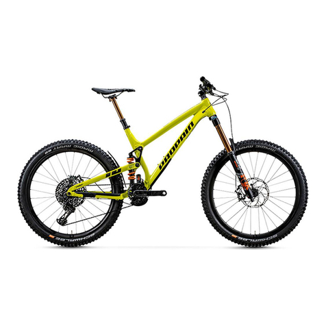
PROPAIN Ekano 165 User manual

EKANO
QUICKSTART- /ASSEMBLY INSTRUCTIONS -
READ BEFORE YOUR FIRST RIDE!
DÉMARRAGE RAPIDE /NOTICE D’ASSEMBLAGE -
A LIRE AVANT TOUTE SORTIE!
INICIO RÁPIDO /INSTRUCCIONES DE MONTAJE -
LEER ANTES DE LA PRIMERA SALIDA!

Propain Bicycles GmbH
Schachenstraße 39
88267 Vogt
Germany
Managing directors Robert Krauss / David Assfalg
Phone: +49 751 201802-22
Email: info@propain-bikes.com
Product description: Propain Ekano 165 & 150 - EPAC-Mountainbike
Frame Number: Size-Year-Month-Model-001->999 *
Article number: 000871-AD
Year of Construction: 2019
Model year: 2020
Product name /-number of battery: Shimano Steps 8035 / KBTE8035A
Product name /-number of engine: Shimano EP8 / DU-EP800
Product name /-number of battery charger: Shimano / K-ECE60001X
Place and date
Vogt, 22.7.2019
Signature managing director Signature CE-Documentation representative
Dipl. Ing. Robert Krauss BEng Florian Gärtner
The above-mentioned products comply with the requirements
of the following European directives:
2006/42/EG Machinery directive
2014/30/EU Electromagnetic compatibility
2014/35/EU Low voltage directive
DIN EN ISO 12100:2010 Risk assessment
EN ISO 4210:2014 und :2015
EN 15194:2017
*
Size: SM, MD, LG, XL
Year: 19, 20, 21 etc.
Month: 01, 02, 03 etc.
Model: E = Ekano
001 -> 999 consecutive Numbers
//EC-DECLERATION OF CONFORMITY ACCORDING TO EU-MACHINERY DIRECTIVE 2006/42/EG

//SCOPE OF DELIVERY

1 2 3
45 6
//UNPACKING
Carefully open the top of the bike box ensuring no damage is
caused to internal parts whilst opening the box.
Remove the xation of the handlebar, the xation of the rear
triangle and the xation of the fork.
→Carefully remove the handlebar from its xation, to
prevent possible damage to the paint.
Carefully remove both wheels.
→Be careful to avoid damages.
Carefully remove the bike.
→Watch the handlebars, suspension fork and rear
derailleur. Fix the bike to a work stand for further
assembly or place it on the ground in the rear end
xation.
Remove the box for the small parts and open it.
→This box contains pedals, saddle, torque wrench,
small parts as well as clothing/merchandise
purchased with the bike.
→For instructions on using the torque wrench,
see next page. Detach the rear derailleur from the rear end xation.

5
2 3
3 mm
4 mm
5 mm
6 mm
T25
1
//USING THE TORQUE WRENCH
Set zero position:
Before each use of the torque wrench it must be checked
whether the pointer of the scale is set to "0" in the unloaded
state. If not, hold the torque wrench tight and turn the
extension clockwise until the pointer is at "0".
Five different bits are stored in the handle of the torque
wrench:
• 3 mm hexagon socket bit
• 4 mm hexagon socket bit
• 5 mm hexagon socket bit
• 6 mm hexagon socket bit
• T25 socket bit
Tightening bolts with the torque wrench:
1. Insert the appropriate bit into the extension of the
torque wrench.
2. Set zero position.
3. Turn the bolt clockwise until the pointer indicates the
desired torque value on the scale.
→Only bolts with right-hand thread can be tightened.
→The torque wrench covers a range from 0 to
10Nm. Higher torque values cannot be set with
this torque wrench!

1 2
43
//MOUNTING THE HANDLEBAR
1. Unscrew the stem clamp bolts.
2. Remove the handlebar clamp and the bolts.
1. Attach the handlebar to the stem.
2. Attach the handlebar clamp and screw in the bolts a few
turns by hand.
1. Screw in the two upper clamping bolts and tighten both
bolts with the torque lasered on the clamp or stem.
2. Screw in the two lower clamping bolts and tighten both
bolts with the torque lasered on the clamp.
1. Center the handlebar and adjust the angle of the handlebar according to your personal preferences.
2. Adjust the brake levers and the shifters to the angle of the handlebar.

5
10 Nm
//MOUNTING THE REAR DERAILLEUR
Mount the derailleur to the derailleur hanger of the frame using a
5 mm hex key.
→The derailleur stop must be at the lug of the derailleur
hanger.
→Tighten the derailleur with a torque of 10 Nm.

1 2 3
4 5
//MOUNTING THE FRONT WHEEL
Remove the thru axle from the fork. 1. Remove the transport securing device that is tted
between the brake pads.
2. Store the transport securing device for future transport
of your bike.
1. Put the front wheel into the dropouts of the fork. The
brake rotor must be placed between the brake pads.
2. Open the lever of the thru axle and slide the axle through
the non-drive side (left in the direction of travel) fork
dropouts and hub of the wheel.
Rotate the lever clockwise until there is only a small gap left
between lever head and dropout.
1. Close the lever of the thru axle.
2. There must be no gap between lever head and dropout.
→Closing the lever should require an increasing amount of hand force until the lever is fully closed.
To increase lever tension, open the lever and turn it clockwise. Close the lever to recheck lever tension.
Repeat until the tension is sucient, then close the lever.
Depending on the fork manufacturer, the thru axle must be pushed from the right or left through the dropout of the fork.

2 3
4
1
2
1
5
//MOUNTING THE REAR WHEEL
1. Remove the thru axle from the frame.
2. Remove the transport securing device that is tted
between the brake pads.
3. Store the transport securing device for future transport
of your bike. 1. Insert the rear wheel into the dropout of the frame.
→The brake rotor must be placed between the brake
pads.
→Put the chain on the smallest sprocket of the
cassette.
2. Slide the thru axle from the brake side (left in the
direction of travel) into the frame dropout and hub of
the wheel.
Screw the thru axle into the dropout using a 6 mm hex key
and tighten the thru axle to a torque of 12 Nm.
Activate the Cage Lock function. Pull the cage of the rear
derailleur forward and press the Cage Lock button with the
symbol .
→The rear derailleur cage remains tilted forward when
the Cage Lock function is activated.
This simplies the
installation of the rear wheel.
Deactivate the Cage Lock function. Pull the cage of the
derailleur slightly forward and carefully return the derailleur
to its original position.

R L
1 1
2
3
//MOUNTING THE PEDALS
One of the pedals has a right- and the other a left-hand thread.
Most pedals have the letter “L” and “R” stamped on the end of
the thread. Some pedals come with a groove in the ange of
the left pedal.
1. Slightly grease pedal thread.
2. Turn the left pedal counter-clockwise to screw it into the
thread of the left crank arm and tighten the pedal to a
torque of 35Nm.
3. Turn the right pedal clockwise to screw it into the thread
of the right crank arm and tighten the pedal to a torque
of 35Nm.
//MOUNTING THE SADDLE
1. Attach the upper clamp to the saddle frame.
2. Adjust the saddle to your personal preferences and
screw in the clamping bolts.
Adjust the seat height:
Caution: When adjusting the seat height, the cable of the seat
post must be pushed or pulled in or out the frame. Otherwise
the cable may get damaged!
1. Open the saddle clamp.
2. Push the seat post carefully and slowly into the frame
or pull the seat post out of the frame. At the same time
push or pull the cable in or out the frame.
3. Close the saddle clamp.
Unscrew the bolts of the saddle clamp and remove the upper
clamp.

1 2 3
//INFLATING THE TIRE
1. Inate the tire to about 2 bar.
2. Check the correct t of the tire.
→The tire must contact the rim evenly around its
entire circumference. If not, release the air, press
the tire into the center of the rim bed and repeat
the procedure.
→Have the tire seat checked by a professional if in
any doubt.
3. Slowly rotate and shake the wheel to distribute the
sealing uid over the entire inner surface of the tire.
4. After the tire bead is fully seated, reduce the pressure to
your own requirements.
5. Screw on the valve cap.
6. Carry out a short test ride and check the tire pressure
regularly.
If you have ordered your bike with tubeless setup, you must ll both tires with the enclosed sealing uid before the rst ride.
1. Release the air from the tire completely.
2. Unscrew the valve cap.
3. Unscrew the valve insert from the valve using the valve
key supplied.
1. Shake the provided sealing uid for about one minute.
2. Fill the sealing uid through the valve into the tire.
Approximately 60 ml of sealing uid should be used
per tire.
3. Screw the valve insert into the valve using the valve key
and tighten it by hand.
If you have ordered your bike without tubeless setup, inate the tires to a pressure of about 2 bar.

1 2
//DISMOUNTING THE BATTERY PACK
1. Insert the key into the lock of the cover and turn the key
counterclockwise.
2. Swing the cover down and remove the cover.
1. Insert the key into the lock of the battery pack and turn the key clockwise.
→The battery pack falls into the latch of the removal position.
2. Hold the battery pack, press the release button by hand, swing the battery pack downwards and remove the battery pack.

„ click “
1 2
//MOUNTING THE BATTERY PACK
1. Place the lower end of the battery on the lower guide.
2. Swing the battery upwards until it clicks into the lock.
→The battery snaps into the lock with a clearly audible "click".
3. Verify the tight t of the battery pack.
1. Put the lower end of the cover on the lower guide and
swing the cover upwards.
2. Insert the key into the lock of the cover and turn the key
clockwise.
3. Verify the tight t of the cover.

1 2
//CHARGING THE BATTERY PACK
// CHARGING THE MOUNTED BATTERY PACK // CHARGING THE DISMOUNTED BATTERY PACK
Before charging and using the battery pack, read the user manual of the battery pack!
1. Remove the dust cap from the charging connector.
2. Connect the charger to the charging socket of the battery pack and connect the charger to a
mains socket.
→The battery pack is fully charged when the LED on the charger turns off.
Before charging and using the battery pack, read the user manual of the battery pack!
1. Dismount the battery pack (see previous page).
2. Plug the adapter onto the charging socket of the battery pack.
You will nd the adapter in the box with the other accessories.
3. Connect the charger to the socket of the adapter and connect the charger to a mains
socket.
→The battery pack is fully charged when the LED on the charger turns off.

1. Take the enclosed tool for mounting the connector.
2. Using the tool, carefully plug the connector of the cable between the display and the drive unit into the free slot on the underside of the display.
-> The cable must not bend.
-> The connector must engage noticeably.
1. Nimm das beiliegende Werkzeug zur Montage des Steckverbinders zur Hand.
2. Stecke den Steckverbinder des Kabels zwischen Display und Antriebseinheit mit Hilfe des Werkzeugs vorsichtig in den freien Steckplatz
auf der Unterseite des Displays.
-> Das Kabel darf nicht umknicken.
-> Der Steckverbinder muss spürbar einrasten.
1
//CONNECTING DISPLAY AND DRIVE UNIT
1. Take the enclosed tool for mounting the connector.
2. Using the tool, carefully plug the connector of the cable between the display and the drive unit into the free slot on the underside of the display.
→The cable must not bend.
→The connector must engage noticeably.

A
B
C
D
-
+
1
//SWITCHING ON YOUR BIKE
Before the rst use the battery pack must be activated by connecting it to the charger. The bike cannot be switched on without activating and charging the battery pack!
1. Press the ON/OFF button on the down tube.
→After about three seconds the system is activated and the display on the handlebars turns on.
→The pedals must not be loaded during activation. The system is calibrating.
2. Adjust the support level via the rocker switch on the handlebar. The upper rocker increases the support, the lower rocker decreases it.
→You can choose between the three support levels ECO, TRAIL and BOOST.
The display shows the following information:
• A: Battery level
• B: Current speed
• C: Assist mode
• D: Assist gauge

A B
1
Your bike is delivered with a basic adjustment of the suspension elements. Before the rst ride, the air pressure in the suspension elements must be adjusted to your body weight.
//ADJUSTING THE SUSPENSION ELEMENTS
1. Unscrew the valve cap of the shock / fork.
2. Screw on the shock pump and pump the shock / fork up to the required pressure.
→Observe the instructions for operating the shock pump.
→We recommend a SAG* of 15% - 20% on the fork and 20% - 30% on the shock.
Please pay attention to the manufacturer's instructions of the suspension elements for the air
pressure. The corresponding manuals are included.
3. Unscrew the shock pump and screw the valve cap onto the valve.
* The air pressure of your suspension elements is adjusted via the so-called
SAG (negative travel). The SAG is the degree by which the shock and the fork
compresses under the weight of the rider. To adjust the SAG, sit on the bike with
all your cycling equipment (helmet, backpack, shoes, etc.) and take a normal
riding position. No air can escape when unscrewing the shock pump.

1 2
A
B
C
D
D
D
D
//BEFORE YOUR FIRST RIDE
PROVISIONS FOR USE
Observe the basic provisions for the EKANO:
INTENDED USE
The intended use of Bikes is divided into ve different
categories – ranging from the use on paved roads through to
downhill or freeride use.
The EKANO must only be used in accordance with the
provisions of Category 4 or below.
Details can be found in the user manual of your bike.
PERMISSIBLE TOTAL MASS
The permissible total mass (rider + bicycle + equipment +
luggage) is 130 kg and may not be exceeded!
USER MANUAL
In addition to these instructions, please refer to the user
manual of your bike. All information contained therein must
have been read and understood!
REGULATIONS ACCORDING TO THE GERMAN TRAFFIC REGULATIONS
(STRASSENVERKEHRS-ZULASSUNGSORDNUNG STVZO)
If you want to use the EKANO on public roads, a front and rear light, a white front reector, a red rear reector and spoke
reectors must be attached to the EKANO. If pedals are tted retrospectively, make sure that they have yellow reectors that act
forwards and backwards.
These regulations are for the use on public roads in Germany. If the bicycle is used in another country, the requirements
applicable there must be observed.
Pos. Description Special notes
A front light and white
reector
The front and rear lights and reectors must be tted at dusk, in the dark or whenever
required by visibility conditions.
The lights and reectors must be xed during operation and
be protected against accidental movement under normal operating conditions and must
be permanently operational. The front light must be set so that other road users are not
blinded. The lights and reectors must not be covered.
B rear light and red
reector
Cpedal reector Both pedals must have yellow reectors working forward and backward.
Dspoke reector Two spoke reectors must be tted to the front and rear wheel.

// BEFORE YOUR FIRST RIDE
Before your rst ride, check all basic functions of your bike to ensure that there are no assembly errors or transport damages. If there are any defects or aws, you should have your bike inspected and
repaired by a qualied bicycle mechanic. Never ride with a defective bike!
WHEELS / TIRES Lift the wheels one after the other and spin them.
→The wheels must spin smoothly.
→The wheels must run true, without moving up and down or from side to side.
→The tires must not rub against the frame.
Check the tire pressure.
→The tire pressure should be about 2 bar. The maximum tire pressure of the wheel and of the tire used must not be exceeded.
Check the tightening torque of the thru axles.
→The lever of the thru axle of the front wheel must be closed rmly!
→The thru axle of the rear wheel must be tightened to 12 Nm!
COMPONENTS Verify the tight t of the stem: Stand in front of the bike with the front wheel between your knees and try to turn the handlebar left and right.
→It should not be possible to turn the handlebar with normal force.
Check the headset for play: Stand next to your bike, pull the front brake lever and gently push the bike backwards and forwards.
→No bearing play must be detectable.
Make sure that all components are tight.
→Tighten the parts to the proper torque, if need be. In case of doubt, contact the Propain Service.
FRAME Check the frame for damages and deformation.
→There must be no damages.
FORK /
SHOCK
Sit on the bike with all your cycling equipment (helmet, backpack, shoes, etc.) and take a normal riding position.
→We recommend a SAG of 15% - 20% on the fork and 20% - 30% on the shock.
→If necessary, change the air pressure of your suspension elements. If you have ordered a shock with steel spring you have already chosen a spring rate corresponding to
your weight. Details can be found in the user manual of your bike.
BRAKES Check brake eciency: Pull one brake lever after the other while standing and push the bike backwards and forwards.
→The front and rear wheel must lock when the brake lever is pulled.
Check whether the brake hoses and connections are losing brake uid and check them for defects.
→Brake uid must not escape at the connections.
Break in the brake pads. Choose a road away from public roads and brake 20 to 30 times with the front or rear brake from a speed of 30 km/h down to 5 km/h. You should brake as
hard as possible without locking one of the wheels. Repeat the process for the other brake. Only then the brake can show its full braking power.

Suspension Leverage Ratio
0
3,4
3
2,6
3,2
2,8
2,4
2,2 20 40 60 80 100 120 140 160 180
//TECHNICAL SPECIFICATIONS EKANO - Standards
Maximun fork lenght 170mm
Shock length 230 mm
Shock travel 57,5 / 62,5 mm
Shock mount top 8mm x 25mm
Shock mount bottom Propain custom ipchip set
Rear wheel travel 150 / 165mm
Brake mount Post mount 203
Seat post diameter 31,6mm
Head set (S.H.I.S.) Top: ZS44 / Bottom: ZS56
Rear wheel axle Sixpack axle (Boost)
Rear hub width 148mm (Boost)
Tire size 27,5" / 29 " / Mix
Engine Shimano E8000 series DUE8000A
Chain guide Shimano SM-CDE80
Battery Shimano BT-E8035
Charging port Shimano EW-CP100
Speed sensor Shimano SM-DUE11
This manual suits for next models
1
Table of contents
Languages:
Other PROPAIN Bicycle manuals
PROPAIN
PROPAIN Ekano 165 2020 User manual
PROPAIN
PROPAIN RAGE User manual
PROPAIN
PROPAIN TYEE CARBON User manual
PROPAIN
PROPAIN 001464-AL Installation instructions
PROPAIN
PROPAIN tyee 2020 User manual
PROPAIN
PROPAIN HUGENE User manual
PROPAIN
PROPAIN EKANO 2 AL User manual
PROPAIN
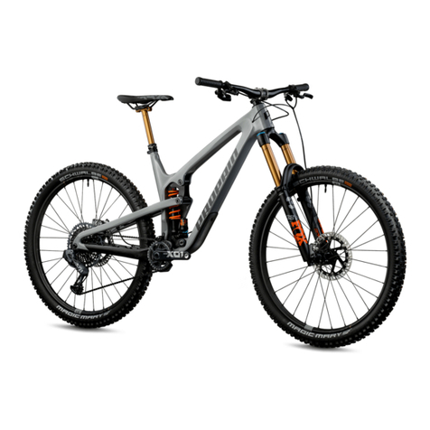
PROPAIN SPINDRIFT Series User manual
PROPAIN
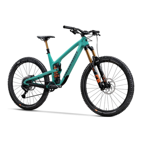
PROPAIN TYEE User manual
PROPAIN
PROPAIN TYEE User manual
