Proxitron Piros OKAxx16 Series User manual
Bedienungsanleitung
User Manual
Piros Infrarot Sensor
OKA / OKB __16

2
Allgemeines
Wir freuen uns, dass Sie sich für einen PROXITRON Infrarot Sensor zur berührungslosen Objekterfassung
entschieden haben.
Für den funktionsgerechten Einsatz und die Bedienung bitten wir Sie, diese Bedienungsanleitung sorgfältig
zu lesen. Sie enthält alle wichtigen Informationen, um eine sichere und langlebige Arbeitsweise des Infrarot
Sensors zu gewährleisten.
Diese Bedienungsanleitung beschreibt die kompakten Infrarot Sensoren der Serie OKA __16, und OKB
__16. (nachfolgend PIROS Infrarot Sensor genannt).
1. Hinweise und Sicherheitsbestimmungen
1.1 Bestimmungsgemäße Verwendung
Diese Sensoren dienen ausschließlich zur berührungslosen Erfassung heißer Objekte.
Ein nicht bestimmungsgemäßer Einsatz, welcher der Beschreibung in dieser Bedienungsanleitung
widerspricht, kann zum Verlust jeglicher Gewährleistungsansprüche gegenüber dem Hersteller führen.
1.2 Eigenmächtige Umbauten und Veränderungen am Gerät
Soweit nicht vom Hersteller schriftlich genehmigt, ist es untersagt, technische Veränderungen am Gerät
vorzunehmen. Sollte dem zuwider gehandelt werden, übernimmt der Hersteller keine Haftung für eventuell
daraus entstehende Schäden. Des Weiteren führt dies automatisch zum Verlust jeglicher
Gewährleistungsansprüche.
1.3 Wartung und Pflege
Das Gerät besitzt keine Teile, die einer Wartung unterliegen.
Achtung: Die Linse kann bei leichter Verschmutzung mit trockener, ölfreier Druckluft gereinigt werden. Bei
stärkerer Verschmutzung empfehlen wir ein weiches, trockenes Tuch, wie es auch bei der Reinigung von
Kameraobjektiven zum Einsatz kommt.
1.4 Gewährleistung
Die PROXITRON GmbH wird defekte Teile, die durch Fehler im Design oder der Herstellung begründet sind,
während des ersten Jahres ab Verkaufsdatum ersetzen oder reparieren. Davon abweichende Regelungen
können schriftlich beim Kauf des Gerätes vereinbart werden. Ist einer Rücksendung zur Garantiereparatur
zugestimmt worden, schicken Sie das Gerät bitte an die PROXITRON GmbH zurück.
Die Garantie erlischt, wenn das Gerät geöffnet, auseinander genommen, verändert oder anderweitig zerstört
wurde. Die Garantie erlischt auch, wenn das Gerät falsch angewendet oder unter Bedingungen benutzt oder
gelagert wurde, die nicht der Spezifikation in den technischen Daten entsprechen.
Die PROXITRON GmbH haftet nicht für Zerstörungen, Verluste, einschließlich Gewinnverluste und
Folgeschäden, die bei der Nutzung des Gerätes eventuell entstehen oder die aus Defekten bei Design und
Herstellung des Gerätes resultieren.
Der Verkäufer übernimmt keine Garantie, dass das Gerät für eine beim Kunden vorgesehene spezielle
Applikation einsetzbar ist.
1.5 Urheberrechte
Alle Rechte und Änderungen vorbehalten. Die Änderung der in diesen Unterlagen enthaltenen Angaben und
technischen Daten, auch ohne vorherige Ankündigung, bleibt vorbehalten.
Ohne ausdrückliche schriftliche Genehmigung des Herstellers, darf kein Teil dieser Unterlagen vervielfältigt,
verarbeitet, verbreitet oder anderweitig übertragen werden.
Es wird keine Garantie für die Richtigkeit des Inhalts dieser Unterlagen übernommen.
1.6 Erklärung
Änderungen, die dem technischen Fortschritt dienen, behält sich die PROXITRON GmbH vor.

3
Einführung
2 Lieferumfang
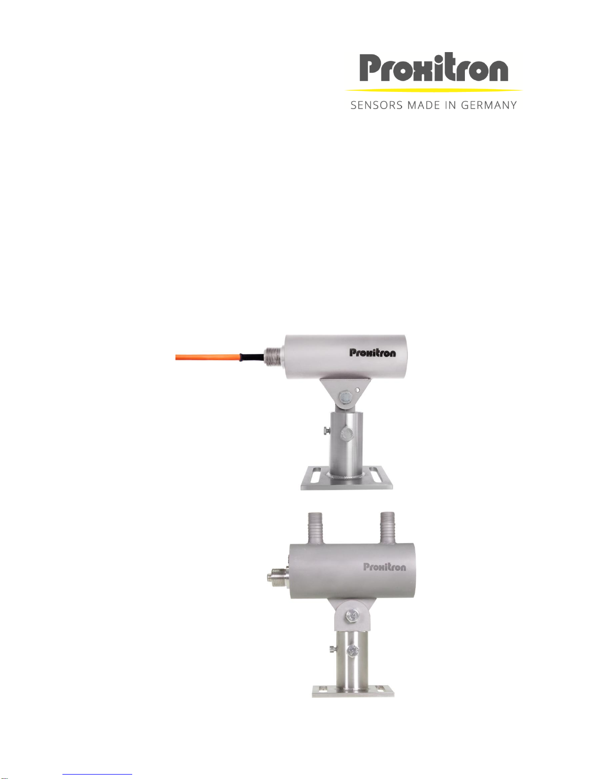
PIROS Infrarot Sensor
Schraubendreher
Hinweis: Bei Geräten mit Anschlussstecker sind passende Anschlusskabel nicht im Lieferumfang enthalten.
Bitte bestellen Sie die erforderlichen Kabel in der von Ihnen gewünschten Länge separat.
2.1 Anwendungsbereich und Funktionsprinzip
Die digitalen PIROS Infrarot Sensor sind speziell für den industriellen Einsatz konzipiert. Sie eignen sich zur
Erfassung von Objekten mit einer Temperatur ab 100 °C, wie z.B. Metalle, Grafit, Keramik oder Glas.
Die PIROS Infrarot Sensoren können für allgemeine Anwendungen eingesetzt werden. Für Metalle mit stark
glänzenden Oberflächen, bedingt durch den niedrigen Emissionsgrad (ε), ist der PIROS Infrarot Sensor nur
eingeschränkt empfehlenswert.
Durch den soliden Aufbau im kompakten Edelstahlgehäuse ist der Einsatz auch unter rauen
Umgebungsbedingungen möglich. Mit dem PIROS Infrarot Sensor können, je nach verwendeter Optik,
verschiedene Messfleckdurchmesser ab 40 mm realisiert werden. Mit einer Ansprechzeit von 0,3 ms ist das
Gerät auch für die Erfassung schneller Objekte geeignet.
Der PIROS Infrarot Sensor verfügt über einen Stufenschalter zur Einstellung der Ansprechtemperatur und
kann so optimal an die Anwendungen angepasst werden.
Mit dem optionalen LASER Pilotlicht Vorsatz DAK 308 und dem passenden Adapter kann der Sensor exakt
auf das Objekt ausgerichtet werden. Der Lichtpunkt des LASER Pilotlichtes visualisiert annähernd den
Mittelpunkt des Messfleckes.
Der PIROS Infrarot Sensor ist für unterschiedliche Versorgungsspannungen und mit verschiedenen
Ausgangsfunktionen lieferbar. Die Infrarotstrahlung des zu erfassenden Objektes wird im Sensor in ein
elektrisches Signal umgewandelt. Dieses wird digital weiterverarbeitet und löst bei Überschreitung des
eingestellten Schwellenwertes (Ansprechtemperatur) am Ausgang ein Schaltsignal aus.
Technische Daten
3 Gerätedaten
Die PIROS Infrarot Sensoren sind mit diversen Festoptiken, Ansprechtemperaturen,
Versorgungsspannungen und Ausgangsfunktionen lieferbar. Details für das jeweilige Gerät entnehmen Sie
bitte dem Geräteaufkleber oder dem entsprechenden Datenblatt.

4
3.1 Optik
Je nach Anwendung kann das Gerät mit verschiedenen Optiken ausgestattet werden. Diese sind
nachträglich nicht austauschbar und müssen bereits bei der Bestellung festgelegt werden.
Die Art der Optik wird charakterisiert durch den Blickwinkel. Ein größerer Blickwinkel führt bei gleichem
Abstand zu einem größeren Messfleck.
Die Größe des Messfleckes ändert sich in Abhängigkeit zum Abstand vom Objekt. Dieses entnehmen Sie
bitte der folgenden Tabelle.
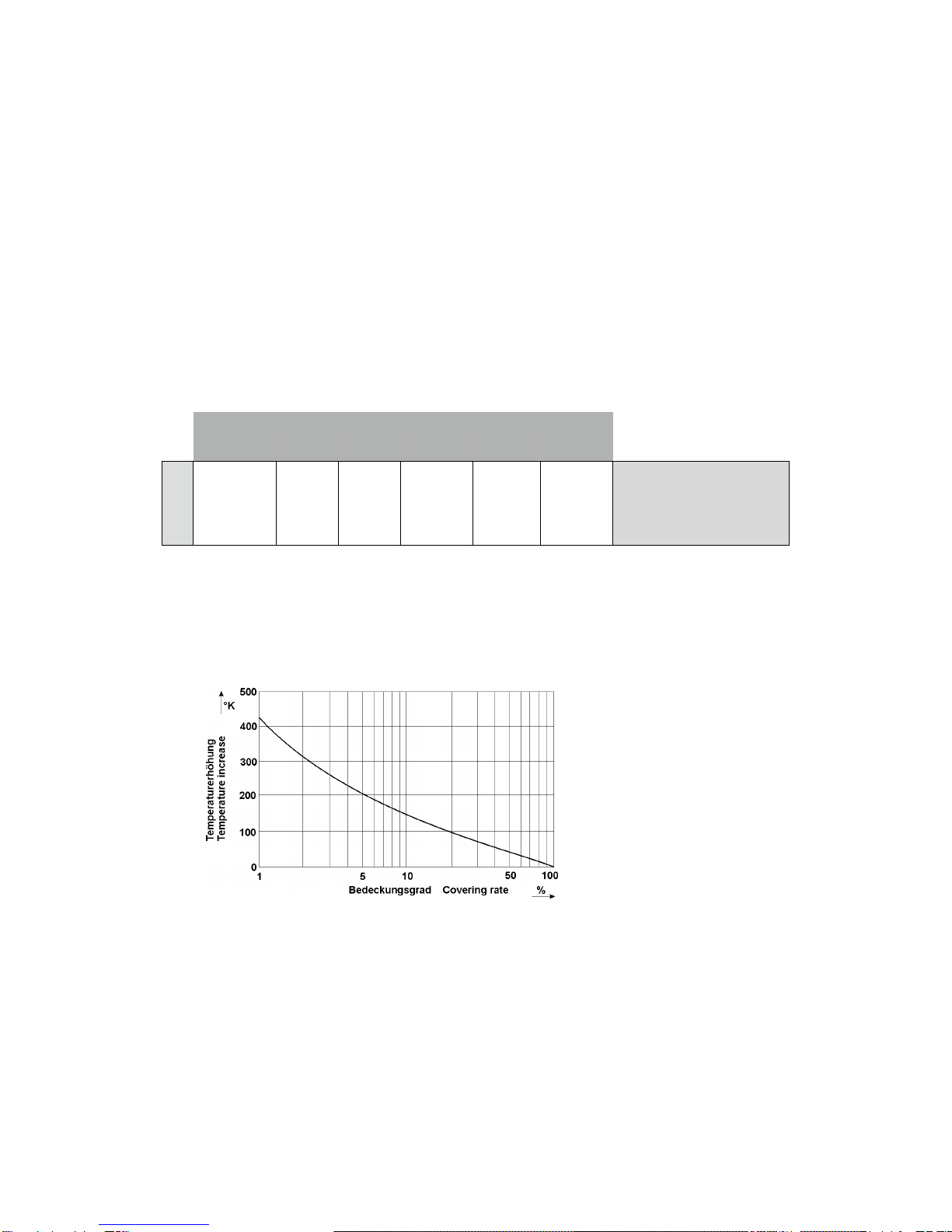
3.2 Ansprechtemperatur
Das zu erfassende Objekt muss mindestens die Ansprechtemperatur des PIROS Infrarot Sensors haben
und den Messfleck vollständig ausfüllen. Bei kleineren Objekten, die den Messfleck nur teilweise ausfüllen,
muss die Objekttemperatur höher sein. Die Abhängigkeit zwischen Bedeckungsgrad und Erhöhung der
niedrigsten erfassbaren Objekttemperatur veranschaulicht die nachfolgende Grafik.
Entsprechend dem Grad der Bedeckung des Messfleckes durch das Objekt, muss dessen Temperatur höher
als die Ansprechtemperatur sein, um eine Erfassung zu ermöglichen.
Beispiel: Bei 500 °C Ansprechtemperatur und 5 % Bedeckung des Messfleckes ist die geringste zu
erfassende Objekttemperatur 700 °C
3.3 Kühlmantel
PIROS Infrarot Sensoren vom Typ OKB sind mit einem Kühlmantelgehäuse ausgestattet. Bei einem
Kühlwasserdurchfluss von 1 l/min (alternativ Luft ca. 50 l/min) mit einer Temperatur von <50 °C ist eine
Umgebungstemperatur von maximal 200 °C zulässig. Der maximale Betriebsdruck liegt bei 5 bar.
Abstand
0 m
1 m
2 m
3 m
4 m
5 m
1°
20 mm
50 mm
60 mm
90 mm
120 mm
150 mm
Meßfleckdurchmesser

5
3.4 Luftanschluss
Zum Schutz der Optik vor Verschmutzung können PIROS Infrarot Sensoren mit einem zusätzlichen
Luftanschluss versehen sein. Um eine zu hohe Geräuschentwicklung für den Spülluftbetrieb zu vermeiden,
sollte die Luftgeschwindigkeit einen Wert von 3 m/s nicht überschreiten. Bei dem Durchmesser von 10 mm
des Luftanschluss entspricht dieser Wert einem Verbrauch von 14 l/min. Der maximale Betriebsdruck liegt
bei < 0,1 bar. Um eine Verschmutzung der Optik durch Spülluft zu vermeiden, muss diese ölfrei, trocken und
staubfrei sein.
3.5 Zubehör OKA / OKB
Für verschiedene Einsatzgebiete steht eine Vielzahl von Zubehörteilen zur Verfügung. Als Zubehör gelten
die Teile, die jederzeit bestellt und vor Ort montiert werden können, z.B.:
Montagewinkel HM 2
Tubus OL19 , OL21
Schutzglas SG1
Pilotlichtvorsatz (Laser) DAK 308
Adapter für Pilotlichtvorsatz OL 26, OL 27
Luftblasvorsatz OL 34, OL 35
Installation und Inbetriebnahme
In diesem Abschnitt wird die Installation und Inbetriebnahme der PIROS Infrarot Sensoren beschrieben.
4. Vorbereitung
Der Einsatzort des PIROS Infrarot Sensor und die einzustellenden Parameter werden durch die Anwendung
bestimmt. Bei der Auswahl des Montageortes müssen die Umgebungsbedingungen, wie zum Beispiel
mechanische Schwingungen, Wasser / Wasserdampf, Umgebungstemperatur, IR-Strahlung, IR-
Hintergrundstrahlung, berücksichtigt werden.
Bei der Verwendung von Infrarot Sensoren mit Luftblasanschluss muss eine ausreichende Versorgung mit
ölfreier, trockener und staubfreier Pressluft gewährleistet sein. Für Geräte mit Kühlwasseranschluss muss
entsprechend eine Kühlwasserversorgung vorgehalten werden.
Weiterhin ist die Kabelführung für die verwendeten Anschlusskabel des PIROS Infrarot Sensors in die
Planung einzubeziehen.
4.1 Umgebungstemperatur
Die Umgebungstemperatur darf die Grenzen der Betriebstemperatur des Infrarot Sensor von -25 °C bis
+70 °C nicht über- oder unterschreiten. Für höhere Umgebungstemperaturen empfehlen wir den Einsatz
eines Gerätes mit Kühlmantelgehäuse ( OKB ) das bei ausreichender Wasserkühlung einen Betrieb bis zu
einer Umgebungstemperatur von +200 °C ermöglicht.
4.2 Atmosphärische Bedingungen
Rauch, Dampf, Staub und andere Verunreinigungen in der Luft sowie eine verschmutzte Optik reduzieren
die zur Erfassung benötigte Infrarotstrahlung. Dies kann dazu führen, dass warme Objekte nicht mehr
zuverlässig erkannt werden. In begrenztem Maße kann diesem Problem mit der Reduzierung der
Ansprechtemperatur entgegengewirkt werden. Durch Verwendung eines Luftblasanschlusses kann die
Optik vor einer zu starken Verschmutzung geschützt werden.
4.3 Elektromagnetische Störungen
PIROS Infrarotsensoren sind für den rauen, industriellen Einsatz konzipiert und entwickelt worden. Die
elektromagnetische Verträglichkeit ( EMV ) der Infrarot Sensoren übertrifft die geforderten und geprüften
Werte der EU-Richtlinie deutlich. Darüber hinausgehende Störpegel können zu Fehlschaltungen führen. Bei
der Auswahl des Montageortes und der Kabelverlegung sollte deshalb Abstand von potentiellen Störquellen
gehalten werden.

6
Installation des PIROS Infrarot Sensors
5. Anforderungen an den Einsatzort
Es wird empfohlen, den PIROS Infrarot Sensor mit der dafür vorgesehenen Halterung und dem justierbaren
Montagefuß HM2 (siehe Zubehörliste) zu montieren. Der Montageort sollte so gewählt werden, dass ein
Winkel von 30° zur Oberfläche des zu erfassenden Objektes nicht unterschritten wird und dass sich im
Blickfeld des Sensors keine anderen Infrarotquellen befinden (Ofentür, Sonnenlicht, Brennschneider,
Halogenlampen, usw.). Der Abstand zwischen Sensor und zu erfassendem Objekt sollte nicht zu gering
gewählt werden, um eine Überhitzung des Sensors durch die Strahlungswärme zu vermeiden. Der minimal
mögliche Abstand ist abhängig von der Objekttemperatur, der Objektgröße und der Verweildauer des heißen
Objektes vor dem Sensor. In der Praxis hat sich ein Montageabstand von >1 m bewährt.
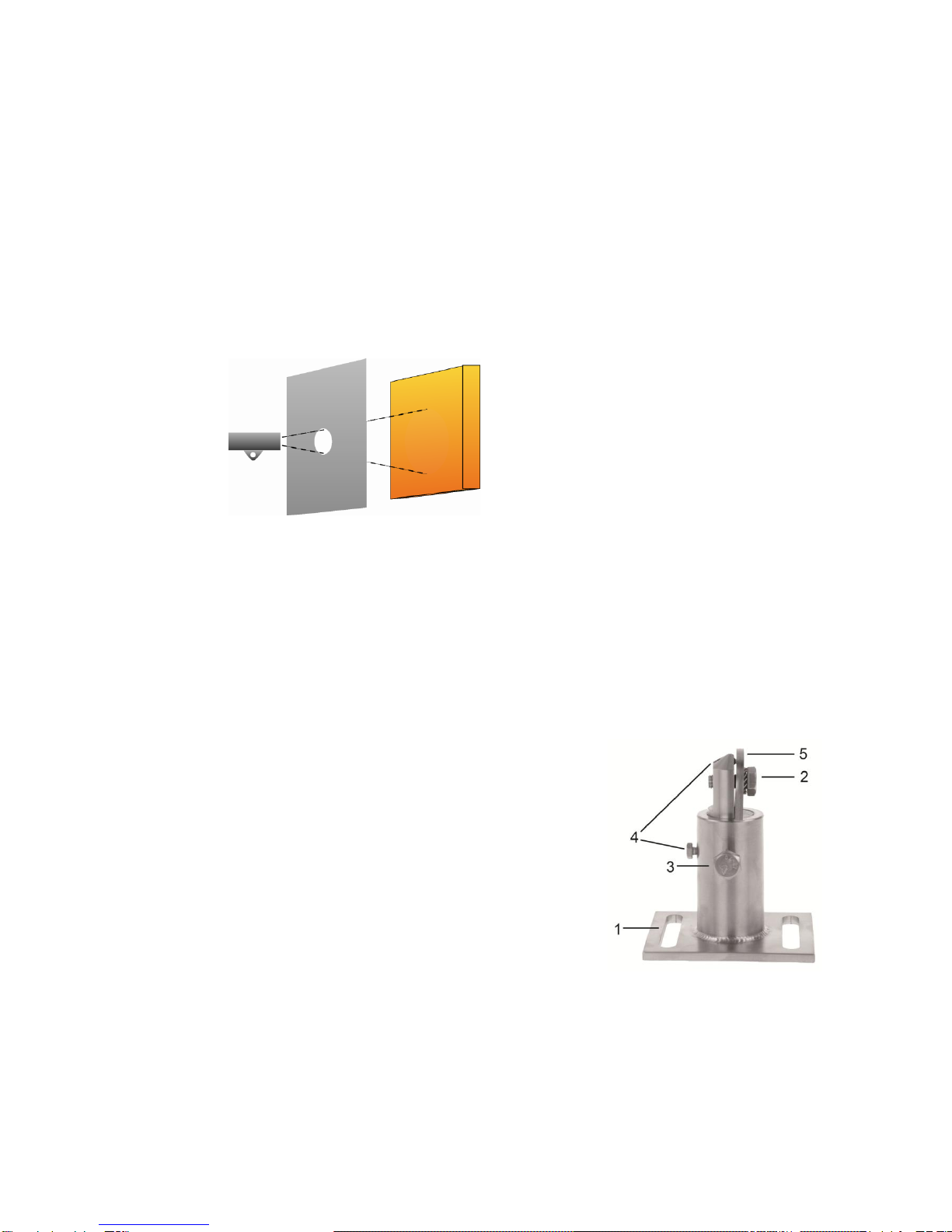
Zum zusätzlichen Schutz des Sensors vor Überhitzung durch Strahlungswärme empfiehlt sich die Montage
hinter einer Metallplatte größer 300 x 300 mm, die nur in Blickrichtung des Sensors mit einer Öffnung
versehen ist.
Zur Ausnutzung der vollen Sensorempfindlichkeit sollte diese Öffnung mindestens 50 mm Durchmesser
haben. Bei einer Objekttemperatur, die deutlich oberhalb der Ansprechtemperatur des Sensors liegt, kann
diese Öffnung kleiner gewählt werden, um den Schutz zu erhöhen.
5.1 Anforderungen an das Bedienpersonal
Die Montage des Infrarot Sensors sollte durch qualifizierte Fachkräfte erfolgen.
Hinweis: Für Schäden, die als Folge einer unsachgemäßen Montage und / oder Anschluss entstehen,
übernimmt die PROXITRON GmbH keine Haftung.
5.2 Montage / Ausrichtung
Es wird empfohlen, den optionalen Montagefuß HM2 mit seiner
Montagefläche (1) mit mindestens 2x M10 Schrauben an einer stabilen
Konstruktion zu montieren. Zum Befestigen des Infrarotsensors lösen Sie
die M10 x 25 mm Schraube (2) und entfernen diese zusammen mit der
Platte (5). Befestigen Sie jetzt den Montageflansch des Infrarotsensors so,
dass er sich zwischen dem beweglichen Schaft des Montagefußes und der
Platte (5) befindet. Die Platte (5) verhindert dass sich der Montageflansch
des Infrarotsensors beim Festziehen der Schraube (2) verdreht und die
Ausrichtung dadurch verstellt wird. Für eine optimale Ausrichtung wird der
optional erhältliche Pilotlichtvorsatz mit dem passenden Adapter auf der
Optikseite des Infrarot Sensors montiert. Die beiden M10 Schrauben (2 und
3) sowie die Fixier- und die Sicherungsschrauben (4) soweit lösen, dass
der montierte Sensor geneigt und gedreht werden kann. Der Schaft lässt
sich insgesamt drehen und herausziehen und ermöglicht eine zusätzliche
Höhenverstellung des Sensors. Das LASER-Pilotlicht einschalten und den Strahl durch Drehen und
Schwenken des Sensors mit dem Montagefuß auf die Mitte der gewünschten Erfassungsposition ausrichten.
Diese Position durch Festziehen der beiden M10 Schrauben (2 und 3) fixieren und mit den beiden M5 und
M6 Schrauben (4) sichern. Pilotlichtvorsatz und Adapter wieder vom Infrarot Sensor demontieren.
Hinweis: Das Laser-Pilotlicht repräsentiert nicht die reale Größe des Messfleckes des PIROS Infrarot Sensor
sondern kennzeichnet dessen Zentrum.

7
5.3 Anschlusskabel
Das Anschlusskabel so verlegen, dass der minimale Biegeradius* nicht unterschritten und die maximal
zulässige Umgebungstemperatur nicht überschritten wird. Für Montageorte mit hoher mechanischer und
thermischer Belastung wird der Einsatz eines Kabelschutzschlauches empfohlen.
*feste Verlegung 4x Leitungsdurchmesser,
gelegentliche Bewegung 8x Leitungsdurchmesser
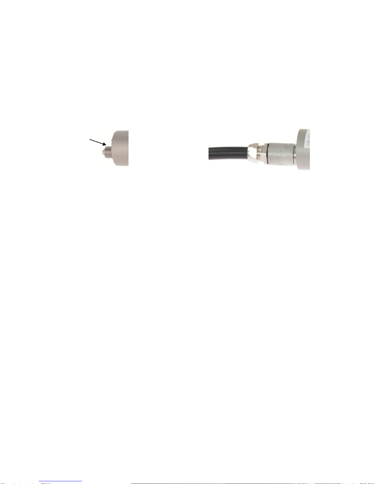
5.4 Anschluss für Kabelschutzschlauch System
Je nach Ausführung verfügen die PROXITRON Lichtschranken über ein 3/4“ Gewinde an dem elektrischen
Anschluss bzw. einem 1/2" Gewinde an der Lichtleiteranschluss. Diese sind für die Montage eines
PROXITRON Schutzlauchsystems vorgesehen, das in verschiedenen Ausführungen als Zubehör lieferbar
ist.
Inbetriebnahme des PIROS Infrarot Sensor
6. Anschluss der Spannungsversorgung
PIROS Infrarot Sensoren sind für verschiedene Betriebsspannungen und Lasten erhältlich. Bitte prüfen Sie
vor der Montage anhand des Geräteaufklebers oder des Datenblattes, ob das Gerät für Ihre
Versorgungsspannung und Last geeignet ist. Verbinden Sie das Gerät, wie auf dem Geräteaufkleber
dargestellt, entsprechend Ihrer Anforderung mit der Versorgungsspannung und den Ausgängen der
nachfolgenden Steuerung bzw. Schaltrelais. Zur Vermeidung von Fehlschaltungen ist das Gerät mit einer
Bereitschaftsverzögerung ausgestattet, die die Ausgänge beim Anlegen der Versorgungsspannung ca. 0,5
Sekunden verzögert aktiviert. Grünes Leuchten der LED signalisiert die Betriebsbereitschaft. Das Gerät
benötigt keine Vorwärm- oder Einlaufzeit.
Hinweis: Der in Geräten für DC-Versorgungsspannung integrierte Verpolungsschutz schützt vor Zerstörung
durch Verpolung der Betriebsspannung. Eine Überschreitung des Betriebsspannungsbereiches bzw. der
Anschluss von AC-Spannungen an DC-Geräte kann zur Zerstörung des Gerätes führen. Für Schäden durch
Falschanschluss übernimmt die PROXITRON GmbH keine Haftung.
Geräte mit Halbleiter-Ausgang signalisieren die Objekterfassung durch Schalten der angelegten
Betriebsspannung. Diese liegt je nach Ausgangsfunktion an den Schaltausgängen des Gerätes an. Die
Halbleiterausgänge sind für einen maximalen Laststrom von 400 mA ausgelegt. Bei Überschreitung wird der
elektronische Kurzschlussschutz ausgelöst, der die Ausgänge vor Zerstörung schützt. Dieses wird durch
rotes blinken der LED signalisiert. Nach Beseitigung der Überlast des Ausgangs kehrt das Gerät selbsttätig
in den normalen Betrieb zurück. Eine Unterbrechung der Betriebsspannung ist nicht notwendig.
Hinweis: Geräte mit potentialfreiem Ausgang sind nicht gegen Überlastung geschützt. Die maximal
zulässige Schaltleistung entnehmen Sie bitte dem Geräteaufkleber oder Datenblatt. Eine Überschreitung
kann zur Zerstörung des Gerätes führen.
¾“ Gewinde

8
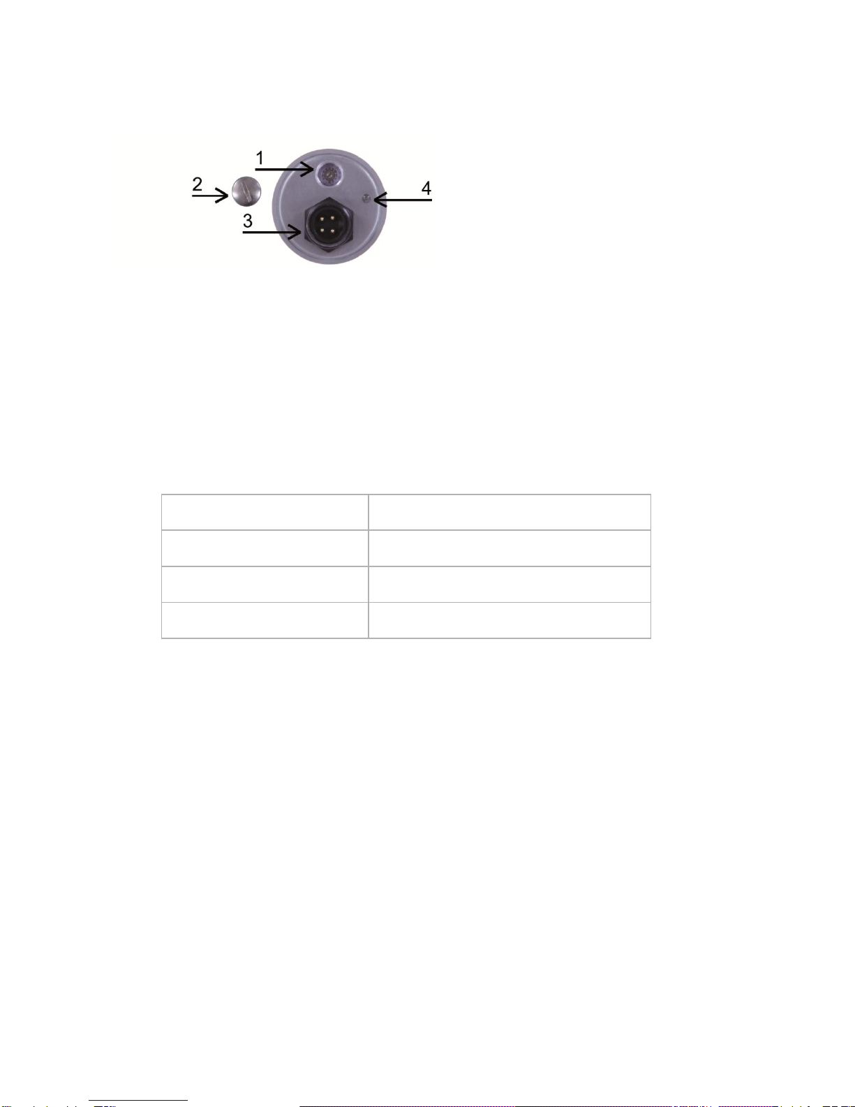
6.1 Bedienung des PIROS Infrarot Sensor
Die Bedienelemente des PIROS Infrarot Sensor befinden sich an der Rückseite des Gerätes.
1) Stufenschalter zur Einstellung der Ansprechtemperatur und Aktivierung der Testfunktion.
2) Verschlussschraube
Hinter der Verschlussschraube befindet sich der Stufenschalter. Zur Gewährleistung der IP-
Schutzklasse muss die Verschlussschraube nach der Schaltpunktverstellung wieder fest
eingeschraubt werden.
3) Anschlusskabel bzw. Anschlussstecker
4) Duo-LED rot / grün
Diese LED signalisiert den Betriebszustand des Infrarot Sensors.
6.2 LED Anzeige
LED GRÜN
GERÄT IST BETRIEBSBEREIT
LED GRÜN BLINKEND
TESTFUNKTION IST AKTIVIERT
LED ROT
OBJEKT WIRD ERKANNT
LED ROT BLINKEND
AUSGANG IST ÜBERLASTET
6.3 Einstellung der Ansprechtemperatur
Der 12-stufige Schalter ermöglicht eine Anpassung der Ansprechtemperatur des PIROS Infrarot Sensor an
die Temperatur des Objektes und die Umgebungsbedingungen.
Die erste Stufe aktiviert die Testfunktion ( siehe untenstehend Testfunktion ). Die Stufe 2 stellt das Gerät auf
die kleinstmögliche Ansprechtemperatur ein. Die Stufe 3 bis Stufe 9 erhöht diese Ansprechtemperatur um je
50 °C und die Stufe 10 bis Stufe 12 erhöht die Ansprechtemperatur um je 100 °C. Um eine sichere
Objekterfassung zu ermöglichen sollte die eingestellte Ansprechtemperatur etwa 150 °C unterhalb der
niedrigsten Objekttemperatur liegen. Eine niedrigere Ansprechtemperatur führt zu schnellerer
Objekterfassung, erhöht jedoch die Gefahr von Fehlschaltungen durch Hintergrundstrahlung (zum Beispiel
durch Öfen). Eine höhere Ansprechtemperatur verringert mögliche Störeinflüsse, reduziert jedoch die
Betriebsreserve und kann zu Fehlern bei der Objekterfassung führen.
Sinnvoll ist es daher den Sensor auf die kleinstmögliche Ansprechtemperatur einzustellen und diese
Schrittweise so lange zu erhöhen, bis keine Störungen durch Hintergrundstrahlung mehr auftreten. Ist es mit
dieser Vorgehensweise nicht möglich einen stabilen Betrieb zu erzielen, kann eine Änderung der
Montageposition oder der Einsatz eines Tubus (OL19 / OL21) zur Reduzierung von Wärmereflexionen aus
der Umgebung Abhilfe schaffen.

9
6.4 Testfunktion
Die erste Stufe des Stufenschalters aktiviert die Testfunktion. Diese simuliert die Erfassung eines warmen
Objektes und schaltet die Ausgänge des Infrarot Sensors dementsprechend. Dieses ermöglicht die
Überprüfung der elektronischen Komponenten des Sensors, der Verbindungsleitungen und der
nachfolgenden Peripherie. Die Testfunktion wird durch grünes blinken der LED am Sensor signalisiert. In
diesem Betriebszustand reagiert der Sensor nicht auf Infrarotstrahlung aus dem Erfassungsbereich.

10
General
Thank you for choosing a PROXITRON infrared sensor for contactless object detection.
Please read this operating instruction carefully to ensure that its use and operation are as intended for. It
contains all the information that is important for guaranteeing safe, long-term use of the infrared sensor.
This operating instruction describes compact infrared sensors in the OKA _16 and OKB _16 series (referred
to hereinafter as PIROS Infrared Sensors).
1. Safety information and regulations
1.1 Use for intended purpose
These sensors serve exclusively for the contactless detection of hot objects.
Any use of them for a purpose other than that intended, or in contravention of the description in these
operating instructions, may vitiate any guarantee claims against the manufacturer.
1.2 Unauthorized conversions or alterations of the equipment
No technical alterations may be made to the equipment unless they are approved by the manufacturer in
writing. The manufacturer accepts no liability for any consequent damage or injury should the foregoing be
contravened. This will moreover automatically mean the loss of any guarantee claims.
1.3 Maintenance and care
The equipment has no parts requiring maintenance.
Caution: in the event of slight contamination, the lens may be cleaned with dry, oil-free compressed air. In
the event of heavier contamination, we recommend a soft, dry cloth, as used for cleaning camera lenses.
1.4 Warranty
During the first year following the date of sale, PROXITRON GmbH will replace or repair parts that are
defective due to errors in design or manufacture. Differing provisions may be agreed on in writing at the time
of purchase of the equipment. If return for repair under warranty has been agreed to, please send the
equipment back to PROXITRON GmbH.
The warranty will lapse if the equipment has been opened, taken apart, altered or destroyed in some other
way. The warranty will also lapse if the equipment has been used incorrectly, or has been used or stored
under conditions that do not correspond with the specifications in the technical data.
PROXITRON GmbH will not be liable for destruction or losses, including losses of profit and consequential
damage, that may occur in the use of the equipment or that arise from defects in the design and manufacture
of the equipment.
The vendor gives no warranty that the equipment can be used for a particular application that the customer
has in mind.
1.5 Copyright
All rights and modifications reserved. The right is reserved to amend the information and technical data
contained in these documents, even without prior announcement.
No part of these documents may be copied, processed, distributed or transmitted in any other way without
explicit written authorization from the manufacturer.
No warranty is given of the correctness of the content of these documents.
1.6 Statement
PROXITRON GmbH reserves the right to make alterations that serve technical progress.

11
Introduction
2. Scope of supply
PIROS infrared sensor
Screwdriver
Note: where equipment is supplied with a connecting plug, suitable connecting cables are not included in the
supply. Please order the required cables separately in the length you desire.
2.1 Area of application and principle of operation
Digital PIROS infrared sensors are specially designed for industrial use. They are suitable for detecting
objects at a temperature of 250°C or higher, such as metals, graphite, ceramic or glass.
PIROS infrared sensors may be used for general applications. Due to its low emissivity (ε), the PIROS
infrared sensor is limited recommendable for use on metals with very shiny surfaces.
Its sturdy construction in compact stainless steel housing permits its use even under harsh ambient
conditions. Depending on the optics used, different measuring spot diameters of 40 mm or greater can be
achieved. With a response time of 0.3 ms, the equipment is also suitable for the detection of fast-moving
objects.
The PIROS infrared sensor has a stepping switch for setting the response temperature, so it can be
optimally adjusted to suit individual applications.
The sensor can be aligned precisely on the object with the optional DAK 308 laser pilot light attachment and
a suitable adapter. The spot of light of the LASER pilot light approximately visualizes the centre of the
measuring spot.
The PIROS infrared sensor is available for different supply voltages and with various output functions. The
infrared radiation from the object to be detected is converted into an electrical signal in the sensor. This
signal is further processed digitally, and a switching signal is given at the output if the set response value
(response temperature) is exceeded.
12
Technical data
3. Equipment data
PIROS infrared sensors are available with various fixed optics, response temperatures, supply voltages and
output functions. Please have a look at the equipment label or the appropriate data sheet for details of the
specific equipment.
3.1 Optics
The equipment can be produced with various optics, depending on the application. These are not
subsequently interchangeable, so they must be specified at the time of ordering.
The The main feature of the optics is characterized by their angle of view. At a given distance, a wider angle
of view implies a larger measuring spot.
The size of the measuring spot varies as a function of distance to the object. Please see the following table
for this.
3.2 Response temperature
The object to be detected must display at least the response temperature of the PIROS infrared sensor and
must fill the measuring spot completely. Smaller objects that only partially fill the measuring spot must have a
higher temperature. The dependence between degree of coverage and an increase in the lowest detectable
object temperature is shown in the following graph.
In accordance with the degree of coverage of the measuring spot by the object, the object's temperature
must be higher than the response temperature to enable a detection.
Example: for a response temperature of 500°C and 5% coverage of the measuring spot, the lowest object
temperature that can be detected is 700°C.
3.3 Cooling jacket
PIROS infrared sensors of the OKB type are fitted with a cooling housing. With a flow rate of cooling water of
1 l/min (alternatively approx. 50 l/min of air) at a temperature < 50°C, a maximum ambient temperature of
200°C is permissible. The maximum operating pressure is around 5 bar.
Abstand
0 m
1 m
2 m
3 m
4 m
5 m
1°
20 mm
50 mm
60 mm
90 mm
120
mm
150 mm
Meßfleckdurchmesser

13
3.4 Air connection
PIROS infrared sensors can be provided with an additional air connection to protect the optics from
contamination. In order to prevent excessive noise being generated by the blowing force of scavenging air,
air speed should not exceed 3 m/s. If the air connection has a diameter of 10 mm, this value corresponds to
a consumption of 14 l/min. The maximum operating pressure is around < 0.1 bar. The scavenging air must
be oil-free, dry and dustfree in order to prevent contamination of the optics.
3.5 OKA / OKB accessories
A large number of accessories are available for various fields of application. Accessories are parts that can
be ordered at any time and installed on site, e.g.:
HM 2 swivel stand
OL19, OL21 tube
SG1 protective glass cover
DAK 308 (laser) pilot light attachment
OL 26, OL 27 adapters for pilot light attachment
Air purge adapter OL 34, OL 36
Installing and putting into service
This section explains how to install PIROS infrared sensors and put them into service.
4. Preparation
The place where the PIROS infrared sensor is to be used and the parameters that are to be set depend on
the application. Ambient conditions such as mechanical oscillations, water / water vapour, ambient
temperature, IR radiation and IR background radiation must be taken into account when selecting the place
of installation.
Where infrared sensors with an air blow connection are used, an adequate supply of oil-free, dry and
dustfree compressed air must be ensured. Correspondingly, a supply of cooling water must be provided for
equipment having a cooling water connection.
Furthermore, the cable run for the connection of the PIROS infrared sensor must be included at the planning
stage.
4.1 Ambient temperature
The ambient temperature must not exceed or fall below the limits of the operating temperature of the infrared
sensor (from -25°C to +70°C). Where ambient temperatures are higher, we recommend the use of
equipment with a cooling housing (OKB), which permits operation up to an ambient temperature of +200°C
with sufficient water cooling.
4.2 Atmospheric conditions
Smoke, vapours, dust and other contamination in the air and soiled optics will reduce the infrared radiation
below the level required for detection. This may mean that warm objects are no longer reliably detected. This
problem can be countered to a limited extent by reducing the response temperature. The optics can be
protected against excessive contamination by the use of an air blow connection.
4.3 Electromagnetic interference
Piros infrared sensors have been designed and developed for use in harsh industrial environments. Their
electromagnetic compatibility (EMC) considerably surpasses the values required and tested by the EU
Directive. Interference levels going beyond these values may cause faulty switching operations. For this
reason, a distance should be observed from potential sources of interference when selecting the place of
installation and when laying cables.
14
Installing the PIROS infrared sensor
5. Requirements at the place of use
It is recommended to install the PIROS infrared sensor with the holder intended for that purpose and with the
HM2 swivel stand (see list of accessories). The place of installation should be selected so that the angle to
the surface of the object to be detected is not less than 30° and that there are no other infrared sources
(oven doors, sunlight, torch cutters, halogen lamps etc.) situated in the field of view of the sensor. To prevent
the sensor's being overheated by the radiated heat, the distance between the sensor and the object to be
detected should not be too low. The minimum possible distance depends on the temperature of the object,
the size of the object, and the time the object spends in front of the sensor. In practice, a distance of > 1 m
has proved to be suitable.
For additional protection against overheating radiation, it is recommended to install the sensor behind a
metal plate larger than 300 x 300 mm, provided with an opening in the sensor viewing direction.
In order to exploit sensor sensitivity to the full, this opening should have a diameter of at least 50 mm. Where
the object temperature is considerably higher than the response temperature of the sensor, a smaller
opening may be chosen to increase protection.
5.1 Requirements for the operating staff
The infrared sensor should be installed by qualified staff.
Note: PROXITRON GmbH accepts no liability for damage or injury that occurs as a consequence of
improper assembly and / or connection.
5.2 Assembly / alignment
It is recommended that the mounting surface (1) of the optional HM2
swivel stand be secured to a stable structure, using minimum 2x M10
screws. For fixing the infrared sensor, loosen the M10 x 25 mm screws
(2) and remove them together with the plate (5). When fasten the
infrared sensor makes sure that the mounting flange of the sensor is
located between the mobile shaft of the swivel stand and the plate (5).
The plate (5) prevents that the mounting flange of the infrared sensor
moves and becomes misaligned while fastening the screw (2). For
optimal alignment, the pilot light device available as an option is to be
mounted on the optic, using a suitable adapter.
Loose the fixing (2) and securing (4) screws to make sensor tilting
possible. Loose the M10 (3) and the corresponding securing (4) screws
for swiveling; at this condition the shaft can be fully rotated and pulled
out, thus allowing for additional adjustment of the sensor in the height.
Turn on the LASER pilot light and align the beam by swivelling the sensor on the centre of the desired
detection position. Fix this position by tightening the two M10 screws (2 and 3) and secure them with the two
corresponding M5 and M6 screws (4). Dismantle the pilot light device and adapter from the infrared sensor.
Note: the laser pilot light does not represent the real size of the measuring spot of the PIROS infrared
sensor, but indicates its centre.
15
5.3 Connecting cable
Lay the connecting cable so that the minimum bending radius* is equalled or exceeded and the maximum
permissible ambient temperature is not exceeded. At installation sites involving heavy mechanical and
thermal stresses, the use of a protective cable conduit is recommended.
* Fixed installation 4x cable diameter
Occasional movement 8x cable diameter
5.4 Connection of cable protection system
Depending on the model, the PROXITRON light barriers are equipped with a 3/4" thread on the electrical
connection or a 1/2" thread on the fiber optic connection. These are provided for mounting of a PROXITRON
cable protection system which is available as an accessory in various versions.
Putting the PIROS infrared sensor into service
6. Connecting the voltage supply
PIROS infrared sensors are available for various working voltages and loads. Before installing the
equipment, please check the equipment label or the data sheet to verify whether the equipment is suitable
for your supply voltage and load. Connect the equipment to the supply voltage and to the outputs of the
following control or switching relay as shown on the equipment label and in accordance with your
requirements. To prevent incorrect connections, the equipment is fitted with a readiness delay that enables
the outputs after a delay of approx. 0.5 seconds when the supply voltage is applied. The LED shining green
indicates operational readiness. The equipment does not require any preheating or running-in time.
Note: the reverse polarity protection integrated into equipment designed for a DC supply voltage protects
against destruction due to inversion of the polarity of the working voltage. Exceeding the working voltage
range or connecting AC voltages to DC equipment can cause destruction of the equipment. PROXITRON
GmbH accepts no liability for damage or injury caused by incorrect connection.
Equipment with a semiconductor output indicates detection of the object by switching the applied working
voltage. Depending on the output function, this is present at the switching outputs of the equipment. The
semiconductor outputs are designed for a maximum load current of 400 mA. If this is exceeded, the
electronic short-circuit protection that protects the outputs against destruction is triggered. This is indicated
by the LED flashing red. After overloading of the output has been eliminated, the equipment returns
automatically to normal operation. Interrupting the working voltage is not necessary.
Note: equipment with potential-free output is not protected against overloading. Please look at the
equipment label or data sheet for the maximum permissible switching capacity. Exceeding this may cause
destruction of the equipment.
¾“ thread
16
6.1 Operating the PIROS infrared sensor
The controls for the PIROS infrared sensor are located on the back of the equipment.
3) Stepping switch for setting the response temperature and enabling the test function.
4) Locking screw
The stepping switch is located behind the locking screw. After adjustment of the switching point,
the locking screw must be screwed in firmly again in order to guarantee the IP protection class.
3) Connecting cable or connecting plug
4) Dual LED red / green
This LED indicates the operating condition of the infrared sensor.
6.2 LED display
LED GREEN
EQUIPMENT IS READY FOR OPERATION
LED FLASHING GREEN
TEST FUNCTION HAS BEEN ENABLED
LED RED
OBJECT IS BEING DETECTED
LED FLASHING RED
OUTPUT IS OVERLOADED
6.3 Setting the response temperature
The 12-stage switch permits adjusting the response temperature of the PIROS infrared sensor to the
temperature of the object and the ambient conditions.
The first stage enables the test function (see test function below). Stage 2 sets the equipment to the lowest
possible response temperature. The stage 3 to stage 9 increased this response temperature by 50°C and
stage 10 to stage 12 increased the response temperature by 100°C. In order to make reliable object
detection possible, the set response temperature should be approximately 150°C below the lowest object
temperature. A lower response temperature means faster object detection, but increases the danger of
incorrect switching operations due to background radiation (from ovens, for example). A higher response
temperature reduces possible disturbing influences, but reduces the operating reserve and can lead to errors
in object detection.
It therefore makes sense to set the sensor to the lowest possible response temperature and then raise it until
there is no more interference from background radiation. If it is not possible to achieve stable operation with
this procedure, altering the mounting position or using a tube (OL19 / OL21) to reduce any heat reflected
from the environment may correct the situation.

17
6.4 Test function
The first stage of the stepping switch enables the test function. It simulates the detection of a warm object
and switches the outputs of the infrared sensor correspondingly. This makes it possible to check the
electronic components of the sensor, the connecting leads and the subsequent peripheral devices. The test
function is indicated by the LED on the sensor flashing green. In this operating condition, the sensor does
not react to infrared radiation coming from the detection area.
Proxitron GmbH
D-25335 Elmshorn
Germany
Tel.: +49-(0)4121-2621-0
Fax: +49-(0)4121-2621-10
www.proxitron.de
BDA OKA_OKB__16.D_E
22.01.2019
This manual suits for next models
1
Table of contents
Languages:
Other Proxitron Accessories manuals


