manuals.online logo
Brands
  1. Home
  2. •
  3. Brands
  4. •
  5. Pyronix
  6. •
  7. Security Sensor
  8. •
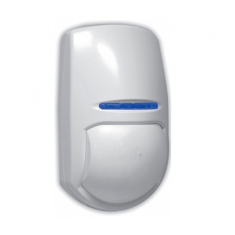
  9. Pyronix KX18DC User manual

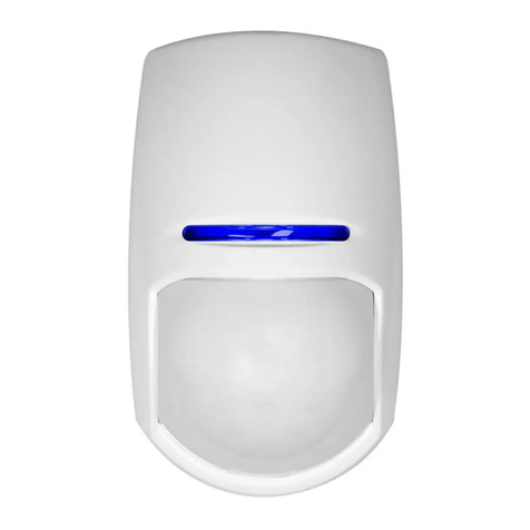
Pyronix KX18DC User manual

TS50131-2-4
EN50131-1
PD6662:2004
Secur i t y Gr a de 3
Envir onme ntal Class 2
TS50131-2-4
EN50131-1
PD6662:2004
Secur i t y Gr a de 2
Envir onme ntal Class 2
TS50131-2-2
EN50131-1
PD6662:2004
Secur i t y Gr a de 2
Envir onme ntal Class 2
3
2
KX18DC®
18m Digital Curtain
PIR Detector
RINS1040-5
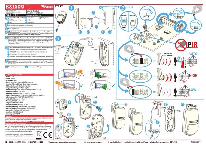
1: Disassembling the KX / Changing the Lens
4: Bracket Connections 6: Sensitivity Settings5: Installation Hints 7: EOL Resistor Headers 8: Remote LED Enable
a) Auto Sensitivity (Default)
b) Wall Bracket
Fitting
a) Ceiling
Bracket
Fitting
b) High Sensitivity
ALARM CONTROL PANEL
+-
ZONE1
COM
TAMPER
TAMPER
KX
+ -
6K8
5K6
4K7
2K2
1K
5K6
4K7
2K2
1K
TAMPERALARM ALARM TAMPER LED
6K8
5K6
4K7
2K2
1K
ALARM
ALARM CONTROL PANEL
+-
ZONE1
COM
TAMPER
TAMPER
KX
+ -
6K8
5K6
4K7
2K2
1K
ALARM ALARM TAMPER LED
KX
+ -
+ -
6K8
5K6
4K7
2K2
1K
5K6
4K7
2K2
1K
TAMPER
Link
ALARM ALARM TAMPER LED
a) Normally Closed
ALARM CONTROL PANEL
+-
ZONE1
COM
TAMPER
TAMPER
+ -
6K8
5K6
4K7
2K2
5K6
4K7
2K2
1K
TAMPERALARM ALARM TAMPER LED
+ -
+ - + -
6K8
5K6
4K7
2K2
5K6
4K7
2K2
1K
TAMPERALARM ALARM TAMPER LED
ALARM CONTROL PANEL
+-
ZONE1
COM
TAMPER
TAMPER
KX
+ -
6K8
5K6
4K7
2K2
1K
5K6
4K7
2K2
1K
TAMPERALARM ALARM TAMPER LED
ALARM CONTROL PANEL
+-
ZONE1
COM
TAMPER
TAMPER
KX
+ -
6K8
5K6
4K7
2K2
1K
5K6
4K7
2K2
1K
TAMPERALARM ALARM TAMPER LED
5K6
4K7
2K2
TAMPER
ALARM TAMPER LED
Link
b) Single End of Line Wiring
ALARM CONTROL PANEL
+-
ZONE1
COM
TAMPER
TAMPER
KX
+ -
6K8
5K6
4K7
2K2
1K
5K6
4K7
2K2
1K
TAMPERALARM ALARM TAMPER LED
ALARM CONTROL PANEL
+-
ZONE1
COM
TAMPER
TAMPER
KX
+ -
6K8
5K6
4K7
2K2
1K
5K6
4K7
2K2
1K
TAMPERALARM ALARM TAMPER LED
KX
+ -
+ - + -
6K8
5K6
4K7
2K2
1K
5K6
4K7
2K2
1K
TAMPERALARM ALARM TAMPER LED
ALARM CONTROL PANEL
+-
ZONE1
COM
TAMPER
TAMPER
KX
+ -
6K8
5K6
4K7
2K2
1K
5K6
4K7
2K2
1K
TAMPERALARM ALARM TAMPER LED
ALARM CONTROL PANEL
+-
ZONE1
COM
TAMPER
TAMPER
KX
+ -
6K8
5K6
4K7
2K2
1K
5K6
4K7
2K2
1K
TAMPERALARM ALARM TAMPER LED
ALARM CONTROL PANEL
+-
ZONE1
COM
TAMPER
TAMPER
KX
+ -
6K8
5K6
4K7
2K2
1K
5K6
4K7
2K2
1K
TAMPERALARM ALARM TAMPER LED
KX
+ -
+ -
6K8
5K6
4K7
2K2
1K
5K6
4K7
2K2
1K
TAMPER
Link
ALARM ALARM TAMPER LED
Link
ALARM CONTROL PANEL
+-
ZONE1
COM
TAMPER
TAMPER
KX
+ -
6K8
5K6
4K7
2K2
1K
5K6
4K7
2K2
1K
TAMPERALARM ALARM TAMPER LED
ALARM CONTROL PANEL
+-
ZONE1
COM
TAMPER
TAMPER
+
6K8
5K6
4K7
2K2
1K
ALARM
KX
+ -
+ - +
6K8
5K6
4K7
2K2
1K
5K6
4K7
2K2
1K
TAMPERALARM ALARM TAMPER LED
ALARM CONTROL PANEL
+-
ZONE1
COM
TAMPER
TAMPER
KX
+ -
6K8
5K6
4K7
2K2
1K
5K6
4K7
2K2
1K
TAMPERALARM ALARM TAMPER LED
ALARM CONTROL PANEL
+-
ZONE1
COM
TAMPER
TAMPER
KX
+ -
6K8
5K6
4K7
2K2
1K
TAMPERALARM ALARM TAMPER LED
ALARM CONTROL PANEL
+-
ZONE1
COM
TAMPER
TAMPER
KX
+ -
6K8
5K6
4K7
2K2
1K
5K6
4K7
2K2
1K
TAMPERALARM ALARM TAMPER LED
KX
+ -
+ -
6K8
5K6
4K7
2K2
1K
5K6
4K7
2K2
1K
TAMPER
Link
ALARM ALARM TAMPER LED
Link
ALARM CONTROL PANEL
+-
ZONE1
COM
TAMPER
TAMPER
+ -
6K8
5K6
4K7
2K2
5K6
4K7
2K2
1K
TAMPERALARM ALARM TAMPER LED
+ -
+ - + -
6K8
5K6
4K7
2K2
5K6
4K7
2K2
1K
TAMPERALARM ALARM TAMPER LED
ALARM CONTROL PANEL
+-
ZONE1
COM
TAMPER
TAMPER
KX
+ -
6K8
5K6
4K7
2K2
1K
5K6
4K7
2K2
1K
TAMPERALARM ALARM TAMPER LED
ALARM CONTROL PANEL
+-
ZONE1
COM
TAMPER
TAMPER
KX
+ -
6K8
5K6
4K7
2K2
1K
5K6
4K7
2K2
1K
TAMPERALARM ALARM TAMPER LED
5K6
4K7
2K2
TAMPER
ALARM TAMPER LED
Link
c) Double End of Line Wiring d) Two Double End of Line Detectors to One Input e) Zone Doubling Example (For Matrix 424, 832, 832+)
15: Compliance and Warranty 16: Contact Information
2: The Printed Circuit Board 3: Cable Entry + Mounting
9: Choose the Connection Type:
10: Powering Up
11: The 18m Curtain Lens 12: The 30m Curtain Lens 13: Dimensions and Weight
b) Lens Illuminator
a) Printed Circuit Board
d) Lens Holder
c) Lens
f) Back
Tamper
e) PCB
Screw
f) Nut
g) Casing Screw
c) Tamper Resistor
Headers
a) Alarm Resistor
Headers b) Terminals a) Mounting Screw
Knockouts
b) Cable Entry
Knockout
c) Case Lid Screw
Fitting
d) Tamper Spring
e) Alarm LED
ON/OFF
f) Sensitivity
Settings
Auto or High
Please note the LOW/AUTO link is inactive on the KX18DC
g) Piro Sensor
DO NOT TOUCH
The KX18DC has 2 set of header pins at the top of
the printed circuit board. These headers are used
to select the End of Line resistance for EOL wiring
applications.
If EOL wiring is not used, leave the headers OFF.
The connection shows the
example values 4k7 for alarm, 4k7
for tamper (EOL). And uses 2k2
for zone doubling EOL.
The connection shows the
example values 4k7 for alarm,
4k7 for tamper (EOL).
The
connection
shows the
example
values 4k7 for
alarm, 4k7 for
tamper (EOL).
The
connection
shows the
example value
4k7 for tamper
(EOL).
The KX18DC has a terminal marked‘LED’ which can
be used to enable the LED in walk test only on an
alarm control panel. This is used when the LED is
disabled via the LED ON/OFF link. To enable this
feature, the LED terminal needs to be connected to
an output on the control panel. When the system is
in walk test mode the output should be at 0v.
The output would be usually programmed as
‘Remote LED enable’
BLUE LED. Once this has distinguished the detector
is ready to use.
NOT READY READY
Avoiding False Alarms
This product is approved for use in the
Residential, Commercial and Light Industrial
Environment. It complies with EN50131-2-2:2008
at security grade 2, environmental class 2. UK
= Suitable for use with systems installed to
PD6662:2010. EXPORT = Suitable for use with
systems installed to EN50131-1:2006+A1:2009
WARRANTY: This product is sold subject to our
standard warranty conditions and is warranted
years. In the interest of continuing improvements
of quality, customer care and design, Pyronix ltd
giving prior notice.
117 x 69 x 50mm
125g (4.4 oz)
without bracket
Model: KX18DC
Colour: White
LED Colour: Blue (PIR)
Casing: 3mm ABS, 0.4mm HDPE in Lens Area
Detection Method: Low noise dual element
pyroelectric sensor
PIR Sensitivity: Auto or High
Temperature Comp: Digital
Detection Range: 18m or 30m
Detection Speed: 0.3 - 3.0m/s
Operating Voltage: 9-16V DC 13.8V DC typical
Current Consumption: 13mA @ 12V (Min), 16mA
@ 12V (Max)
Relay Output: 50mA 60 VDC, 42 VAC (RMS)
Contact Resistance: <10 ohms
Mounting Height: 1.8m - 2.4m
Tamper Switch: 12V 50mA
Storage Temp: -40°C to 80°C
-10°C to 40°C
Nominal working temperature: -30°C to 70°C
Accessories: Wall and Ceiling brackets
Emissions: EN55022 Class B
Immunity: EN50130-4
Optional Lenses: 30m Long Range Lens
ALARM
CONTROL
PANEL
KX
+ -
6K8
5K6
4K7
2K2
1K
5K6
4K7
2K2
1K
TAMPERALARM ALARM TAMPER
Control Panel Output
(0v in walk test)
LED
ALARM
CONTROL
PANEL
KX
+ -
6K8
5K6
4K7
2K2
1K
5K6
4K7
2K2
1K
TAMPERALARM ALARM TAMPER
Control Panel Output
(0v in walk test)
LED
The Installation of The KX15DD
KX15DDKX15DD
Control Panel Control Panel
KX15DD
Control Panel
KX15DD
Control Panel
Wall Brack et Fitting
Ceiling Brack et Fitting
Auto Sensitivity
iring
Zone Doubling Example (Matrix 424,832 or 832+) Two DEOL Detectors T o One Input
Single End of Line W iring (SEOL) Double End of Line W iring (DEOL) Remote LED Enable
High Sensitivity Low Sensitivity
O F F O N ( Defa ult)
S E NS IT IVITY S E TTING S :
Auto, High or Low.
S ee the diagams below
5K6
4K7
2K2
1K
+ –ALARM TAMPER LED
Alarm LED
Pyro Sensor
EOL Resist ance
Headers
EOL Resistor Headers
The KX15DD Printed Circuit Board
iring Connections F or The KX15DD (Examples using 4k7 for alarm, 4k7 for tamper)
The KX15DD has two set s of header pins on the PCB, one on
either side of the connector blocks. These headers are used to
select the End Of Line resistance for EOL wiring applications.
If EOL wiring is not used, leave the headers OFF .
The set to the lef t of the + terminal select s the value of the
resist ance across the ALARM relay . The set to the right of the
TAMPER terminals select s the value of the End Of Line resistor .
If the resist ance value you require
is not select able, leave the
headers of f and wire a resistor
of the required value between the
appropriate terminals as shown.
The KX15DD has a terminal marked ‘LED’ which can be used
to enable the LED in walk test only on a alarm control panel.
This is used when the LED is disabled via the LED ON/OFF link.
To enable this feature, the LED terminal needs to be connected
to an Output at the alarm control p anel. When the system is
is in walk test mode the Output should be at 0V .
The Output would be usually programmed as “Remote LED
enable”.
The KX15DD sensitivity is selected by
the two headers located at the bottom
of the PCB
The sensitivity can be either AUT O,
HIGH or LOW .
To select either of these sensivities
please see the diagrams below .
This symbol illustrates
where the resistors are
connected internally
6K8
5K6
4K7
2k2
1K
LOWAUTO AUTO HI
6K8
5K6
4K7
2k2
1K
5K6
4K7
2K2
1K
+ –ALARM TAMPER LED
LOWAUTO AUTOHI
LOW AUTO AUTO HI
+–ALARM TAMPER LED Control Panel
Output
(0v in Walk Test)
6K8
5K6
4K7
2k2
1K
5K6
4K7
2K2
1K
+ –ALARM TAMPER LED
LOWAUTO AUTOHI
LOW AUTO AUTO HI
5K6
4K7
2K2
1K
T T+AU X - Z1
C O M
5K6
4K7
2K2
1K
5K6
4K7
2K2
1K
+–ALARM TAMPER L ED
6K8
5K6
4K7
2K2
1K
6K8
5K6
4K7
2K2
1K
T T+AUX - Z1
C O M
5K6
4K7
2K2
1K
5K6
4K7
2K2
1K
+–ALARM TAMPER L ED
6K8
5K6
4K7
2K2
1K
6K8
5K6
4K7
2K2
1K
+AU X -
T T+AU X- Z1
C O M
5K6
4K7
2K2
1K
5K6
4K7
2K2
1K
+–ALARM TAMPER LED
6K8
5K6
4K7
2K2
1K
6K8
5K6
4K7
2K2
1K
5K6
4K7
2K2
1K
5K6
4K7
2K2
1K
+AU X -
+AU X -
T T+AU X- Z1
C O M
Link
5K6
4K7
2K2
1K
5K6
4K7
2K2
1K
5K6
4K7
2K2
1K
5K6
4K7
2K2
1K
+–ALARM TAMPE R LED +–ALARM TAMPE R LE D
6K8
5K6
4K7
2K2
1K
6K8
5K6
4K7
2K2
1K
6K8
5K6
4K7
2K2
1K
6K8
5K6
4K7
2K2
1K
6K8
5K6
4K7
2k2
1K
5K6
4K7
2K2
1K
+ –ALARM TAMPER LE D
LOWAUTO AUTO HI
LOW AUTO AUTO HI
This is the default
setting
R INS 1038-3
®
®
®
®
®
DE
C3
E2 E3
E5
C5
®
®
®®
The Installation of The KX15DD
C AB L E E NT R Y
K NO C K O UT
The KX15DD Casing
all Mounting
KX15DDKX15DD
Control PanelControl Panel Control Panel
KX15DD
Control Panel
KX15DD
Control Panel
KX15DD
Wall Brack et Fitting
Ceiling Brack et Fitting
Auto Sensitivity
Normally Closed W iring
Zone Doubling Example (Matrix 424,832 or 832+) Two DEOL Detectors T o One Input
Single End of Line W iring (SEOL) Double End of Line W iring (DEOL) Remote LED Enable
High Sensitivity Low Sensitivity
O F F O N ( Defa ult)
S E NS IT IVIT Y S E TT ING S :
Auto, High or Low.
S ee the diagams below
5K6
4K7
2K2
1K
+ –ALARM TAMPER LED
Alarm LED
Pyro Sensor
EOL Resist ance
Headers
EOL Resistor Headers
The KX15DD Printed Circuit Board
The W iring Connections F or The KX15DD (Examples using 4k7 for alarm, 4k7 for tamper)
The KX15DD has two set s of header pins on the PCB, one on
either side of the connector blocks. These headers are used to
select the End Of Line resistance for EOL wiring applications.
If EOL wiring is not used, leave the headers OFF .
The set to the lef t of the + terminal select s the value of the
resist ance across the ALARM relay . The set to the right of the
TAMPER terminals select s the value of the End Of Line resistor .
If the resist ance value you require
is not select able, leave the
headers of f and wire a resistor
of the required value between the
appropriate terminals as shown.
The KX15DD has a terminal marked ‘LED’ which can be used
to enable the LED in walk test only on a alarm control panel.
This is used when the LED is disabled via the LED ON/OFF link.
To enable this feature, the LED terminal needs to be connected
to an Output at the alarm control p anel. When the system is
is in walk test mode the Output should be at 0V .
The Output would be usually programmed as “Remote LED
enable”.
The KX15DD sensitivity is selected by
the two headers located at the bottom
of the PCB
The sensitivity can be either AUT O,
HIGH or LOW .
To select either of these sensivities
please see the diagrams below .
This symbol illustrates
where the resistors are
connected internally
6K8
5K6
4K7
2k2
1K
LOWAUTO AUTO HI
6K8
5K6
4K7
2k2
1K
5K6
4K7
2K2
1K
+ –ALARM TAMPER LED
LOWAUTO AUTOHI
LOW AUTO AUTO HI
+–ALARM TAMPER LED Control Panel
Output
(0v in Walk Test)
6K8
5K6
4K7
2k2
1K
5K6
4K7
2K2
1K
+ –ALARM TAMPER LED
LOWAUTO AUTOHI
LOW AUTO AUTO HI
T T+AU X - Z1
C O M
5K6
4K7
2K2
1K
5K6
4K7
2K2
1K
+–ALARM TAMPER L ED
T T+AU X - Z1
C O M
5K6
4K7
2K2
1K
5K6
4K7
2K2
1K
+–ALARM TAMPER L ED
6K8
5K6
4K7
2K2
1K
6K8
5K6
4K7
2K2
1K
T T+AUX - Z1
C O M
5K6
4K7
2K2
1K
5K6
4K7
2K2
1K
+–ALARM TAMPER L ED
6K8
5K6
4K7
2K2
1K
6K8
5K6
4K7
2K2
1K
+AU X -
T T+AU X- Z1
C O M
5K6
4K7
2K2
1K
5K6
4K7
2K2
1K
+–ALARM TAMPER LED
6K8
5K6
4K7
2K2
1K
6K8
5K6
4K7
2K2
1K
6K8
5K6
4K7
2K2
1K
+AU X -
Link
5K6
4K7
2K2
1K
5K6
4K7
2K2
1K
+–ALARM TAMPER LED
+AU X -
+AU X -
T T+AU X- Z1
C O M
Link
5K6
4K7
2K2
1K
5K6
4K7
2K2
1K
5K6
4K7
2K2
1K
5K6
4K7
2K2
1K
+–ALARM TAMPE R LED +–ALARM TAMPE R LE D
6K8
5K6
4K7
2K2
1K
6K8
5K6
4K7
2K2
1K
6K8
5K6
4K7
2K2
1K
6K8
5K6
4K7
2K2
1K
6K8
5K6
4K7
2k2
1K
5K6
4K7
2K2
1K
+ –ALARM TAMPER LE D
LOWAUTO AUTO HI
LOW AUTO AUTO HI
This is the default
setting
R INS 1038-3
®
®
®
®
®
®
DE
C2 C3
E2 E3
E5
C5
®
®
®®
®
AUTO HI
LOW AUTO
LED ON
LED OFF
AUTO HI
LOW AUTO
+ -
6K8
5K6
4K7
2K2
1K
5K6
4K7
2K2
1K
TAMPERALARM ALARM TAMPER LED
AUTO HI
LOW AUTO
LED ON
LED OFF
AUTO HI
LOW AUTO
+ -
6K8
5K6
4K7
2K2
1K
5K6
4K7
2K2
1K
TAMPERALARM ALARM TAMPER LED
AUTO HI
LOW AUTO
LED ON
LED OFF
AUTO HI
LOW AUTO
+ -
6K8
5K6
4K7
2K2
1K
5K6
4K7
2K2
1K
TAMPERALARM ALARM TAMPER LED
AUTO HI
LOW AUTO
LED ON
LED OFF
AUTO HI
LOW AUTO
+ -
6K8
5K6
4K7
2K2
1K
5K6
4K7
2K2
1K
TAMPERALARM ALARM TAMPER LED
1. Avoid placing the detector in direct sunlight.
2. Do not let pets and other animals wander freely
whilst the alarm system is armed.
3. Do not mount the detector near heaters or
radiators.
4. Do not mount the detector near open windows or
air vents as draughts may cause false alarms
5. Mount the detector on a stable surface.
6. Do not run cable parallel to mains wiring.


LED ON
LED OFF
EN50131-2-2:2008
EN50131-1
PD6662:2010
Security Grade 2
Environmental Class II
Do not partially or completely obscure the detector’s
Secure Holdings, Pyronix Ltd,
Braithwell Way, Hellaby,
Rotherham, South Yorkshire
S66 8QY
For electrical products sold within the
European Community. At the end of the
electrical products useful life, it should
not be disposed of with household
waste. Please recycle where facilities
exist. Check with your Local Authority
or retailer for recycling advice in your
country.
Customer Support:
+44(0)845 6434 999 (local rate)
or +44(0)1709 535225
Hours: Mon to Fri, 8:00am till 6:30pm
Email: customer.suppor[email protected]
Website: www.pyronix.com
ALARM CONTROL PANEL
+-
ZONE1
COM
TAMPER
TAMPER
KX
+ -
6K8
5K6
4K7
2K2
1K
5K6
4K7
2K2
1K
TAMPERALARM ALARM TAMPER LED
KX
+ -
+ - + -
6K8
5K6
4K7
2K2
1K
5K6
4K7
2K2
1K
TAMPERALARM ALARM TAMPER LED
ALARM CONTROL PANEL
+-
ZONE1
COM
TAMPER
TAMPER
KX
+ -
5K6
4K7
2K2
1K
TAMPER
ALARM TAMPER LED
ALARM CONTROL PANEL
+-
ZONE1
COM
TAMPER
TAMPER
KX
+ -
6K8
5K6
4K7
2K2
1K
5K6
4K7
2K2
1K
TAMPERALARM ALARM TAMPER LED
5K6
4K7
2K2
1K
Link
KX
5K6
4K7
2K2
1K
TAMPER
ALARM TAMPER LED
5K6
4K7
2K2
 0845 6434 999 (UK). +44(0)1709 535 225 [email protected] www.pyronix.com Pyronix Limited, Pyronix House, Braithwell Way, Hellaby, Rotherham, S66 8QY, UK
The following languages are available online via the QR code: Bulgarian, Czech, Danish, German, Greek, Spanish, Finnish, French, Croatian, Hungarian, Italian, Dutch, Norwegian, Polish, Portuguese, Romanian, Russian, Slovak, Slovenian, Serbian, Swedish
KX18DC
Digitaler PIR-Vorhangmelder (18 m) KX18DC
Digitale PIR-gordijndetector, 18 m KX18DC
Rilevatore PIR digitale a cortina 18 m
KX18DC
Détecteur PIR à rideau numérique, portée 18 m
EN50131-2-2:2008
EN50131-1:2006+A1:2009
PD6662:2010
Sicherheitsstufe (SG) 2
Umweltklasse (EC) II
DEUTSCH (Grafikverweise)
Technische Daten
Gewährleistung und Konformität
Kontaktinformationen
Dieses Produkt wird mit unseren standardmäßigen Gewährleistungsbedingungen verkauft und
hat eine 5-jährige Gewährleistung hinsichtlich Fertigungsmängeln. Weitergehende
Informationen hierzu nden Sie unter: www.pyronix.com/warranty
Die Konformitätserklärung und sonstige Konformitätsdokumentation nden Sie unter:
www.pyronix.com/product-compliance.php
Secure Holdings, Pyronix Ltd,
Braithwell Way, Hellaby,
Rotherham, South Yorkshire
S66 8QY
In der Europäischen Gemeinschaft verkaufte Elektroartikel sollten am Ende ihrer Nutzungsdauer
nicht im Hausmüll entsorgt werden, sondern bei den dafür vorgesehenen Annahmestellen
abgegeben werden. Informieren Sie sich bei der zuständigen Behörde oder Ihrem Händler über
die Recyclingmöglichkeiten in Ihrem Land. Dieses Produkt ist für
die Benutzung in Wohnbereichen, Geschäfts- und
Gewerbebereichen sowie in der Leichtindustrie zugelassen.
Website: www.pyronix.com
Modell: KX18DC Farbe: Weiß LED-Farbe: Blau (PIR)
Gehäuse: 3 mm ABS, 0,4 mm HDPE im Linsenbereich
Detektionsverfahren: Rauscharmer pyroelektrischer Doppelelementsensor
PIR-Empndlichkeit: Automatisch (Standard), Hoch, Niedrig Temperaturausgleich: Digital
Detektionsbereich 118 m oder 30 m (linsenabhängig) Detektionsgeschwindigkeit: 0,3 - 3,0 m/s
Betriebsspannung: 9 - 16 V DC; 13,8V DC typisch Leistungsaufnahme: 13 mA bei 12V (min.),
16 mA bei 12 V (max.) Relaisausgang 50 mA, 60 V DC, 42VAC (e.)
Kontaktwiderstand: <10 Ohm Montagehöhe: 1,8 - 2,4 m Sabotageschalter: 12 V, 50 mA
Temperatur: -40°C bis 80°C (Lagerung); -10°C bis 40°C (zertiziert); -30°C bis 70°C (nominal)
Zubehör: Wand- und Deckenhalterung Emissionen: EN55022 Klasse B Störfestigkeit: EN501304
1
2
33
Leiterplatte
Alarm-Widerstandsanschlüsse
Anschlussklemmen
KX demontieren / Linse auswechseln
Kabelzuführung / Montage
Empndlichkeitseinstellungen: Autom. Empndlichkeit (Standard)
Hohe Empndlichkeit
34 Halterungsmontageoptionen
18-m-Vorhanglinse 30-m-Vorhanglinse
Abmessungen und Gewicht
EOL-Widerstandsanschlüsse: Der KX18DC hat zwei Gruppen von Stiftleisten (siehe Abb.).
Diese Anschlüsse dienen zur Auswahl des Leitungsabschlusswiderstands bei Abwendungen
mit EOL-Verdrahtung.
HINWEIS: Lassen Sie die Anschlüsse auf OFF, wenn keine EOL-Verdrahtung
verwendet wird.
Einschalten: Wenn der Melder erstmals eingeschaltet wird, führt er eine
Selbsttestroutine durch (angezeigt durch eine blinkende blaue LED). Wenn die
LED erlischt, ist der Melder betriebsbereit.
35
3
3
3
A
B
C
D
E
36 A
B
3737
Fern-LED aktivieren: Der KX18DC hat einen mit „LED“ gekennzeichneten Anschluss, um die
LED an einer Alarmsteuerungszentrale nur für den Gehtest zu aktivieren. Dieser wird benutzt,
wenn die LED über die Verknüpfung LED ON/OFF deaktiviert wird. Um diese Funktion zu
aktivieren, muss die LED-Anschlussklemme mit einem Ausgang der Steuerzentrale
verbunden sein. Wenn sich das System im Gehtest-Modus bendet, sollte der Ausgang 0 V
betragen. Der Ausgang ist normalerweise als „Fern-LED aktivieren“ programmiert
3738
9N/C - Normally Closed-Verdrahtung (NUR BEISPIEL, SIEHE STEUERZENTRALEN-AN-
WEISUNGEN)
Einzel-EOL-Verdrahtung (NUR BEISPIEL, SIEHE STEUERZENTRALEN-ANWEISUNGEN)
DEOL-Verdrahtung (NUR BEISPIEL, SIEHE STEUERZENTRALEN-ANWEISUNGEN)
2x DEOL-Melder zu Einzeleingang (SEE CONTROL PANEL INSTRUCTIONS)
Zonenverdoppelung Beispiel
A
B
C
D
E
F
G
Sabotage-Widerstandsanschlüsse
Sabotagefeder
Alarm-LED (ON/OFF-Jumper)
Empndlichkeit (siehe Abschnitt 6)
Pyro-Sensor (NICHT BERÜHREN)
Halterungsmontageoptionen: Das Sichtfeld des Melders darf weder ganz noch
teilweise durch große Gegenstände wie Möbel verstellt werden.
Vermeidung von Fehlalarmen: Wenn der Melder erstmals eingeschaltet wird, führt er
eine Selbsttestroutine durch, die durch blinkende LEDs angezeigt wird. Wenn die LEDs
erlöschen, ist der Melder betriebsbereit.
1: Platzieren Sie den Melder nicht in direktem Sonnenlicht.
2: Nach Scharfschaltung des Alarmsystem dürfen sich keine Haustiere (oder andere Tiere)
mehr frei bewegen.
3: Montieren Sie den Melder nicht in der Nähe von Heizkörpern oder -strahlern.
4: Montieren Sie den Melder nicht in der Nähe eines geöneten Fensters oder Luftschachts.
5: Montieren Sie den Melder auf einer stabilen Oberäche.
6: Verlegen Sie Kabel nicht parallel zu Stromleitungen.
10
11
313
314
315
316
3
12
EN50131-2-2:2008
EN50131-1:2006+A1:2009
PD6662:2010
Beveiligingsniveau 2
Milieuklasse II
NEDERLANDS (Diagramverwijzingen)
Technische specificatie
Garantie en conformiteit
Contactgegevens
Dit product wordt verkocht onder onze standaardgarantievoorwaarden en heeft gedurende een
periode van vijf jaar een garantie op fabricagefouten. Voor meer informatie over de garantie gaat
u naar: www.pyronix.com/warranty
De conformiteitsverklaring en verdere documentatie met betrekking tot regelnaleving zijn te
vinden op: www.pyronix.com/product-compliance.php
Secure Holdings, Pyronix Ltd,
Braithwell Way, Hellaby,
Rotherham, South Yorkshire
S66 8QY
Voor elektrische producten die binnen die Europese Unie worden verkocht: Elektrische
producten mogen aan het einde van hun levensduur niet
worden weggegooid bij het huishoudelijk afval. Lever ze indien
mogelijk in bij een locatie voor recycling. Informeer bij uw lokale
instantie of de verkoper naar de recyclingmogelijkheden in uw
land. Dit product is goedgekeurd voor gebruik in huishoudelijke,
commerciële en licht-industriële omgevingen.
Website: www.pyronix.com
Model: KX18DC Kleur: Wit LED-kleur: Blauw (PIR)
Behuizing: 3 mm ABS, 0,4 mm HDPE in lensgebied
Detectiemethode: Lage-ruis pyro-elektrische sensor met dubbel element
Gevoeligheid PIR: Auto (standaard), hoog Temperatuurcompensatie: Digitaal
Detectiebereik: 18 m of 30 m (afhankelijk van de lens) Detectiesnelheid: 0,3 - 3,0 m/s
Bedrijfsspanning: 9 - 16V gelijkstroom 13,8V gelijkstroom typisch
Stroomverbruik: 13 mA bij 12 V (min.), 16 mA bij 12V (max.)
Relaisoutput: 50 mA 60 V gelijkstroom, 42 V wisselstroom (RMS) Contactweerstand: < 10 ohm
Plaatsingshoogte: 1,8 - 2,4 m Sabotageschakelaar: 12 V 50 mA
Temperatuur: -40°C tot 80°C (opslag); -10°C tot 40°C (gecerticeerd); -30°C tot 70°C (nominaal)
Accessoires: Muur- en plafondbeugels Emissies: EN55022 klasse B Immuniteit: EN501304
1
2
33
De printplaat
Weerstandsuiteinden alarm
Terminals
De KX uit elkaar halen/de lens vervangen
Kabelingang/montage
Gevoeligheidsinstellingen: Automatische gevoeligheid (standaard)
Hoge gevoeligheid
34 Montageopties voor beugel
De gordijnlens met een bereik van 18 m Afmetingen en gewicht
De gordijnlens met een bereik van 30m
Uiteinden EOL-weerstand: De KX18DC is voorzien van 2 sets pinnen aan de uiteinden
(zoals afgebeeld). Deze eindstukken worden gebruikt om de EOL-weerstand (End Of Line) te
selecteren voor toepassingen met EOL-bedrading.
OPMERKING: Als de EOL-bedrading niet wordt gebruikt, moet u de
eindstukken NIET plaatsen.
Inschakelen: wanneer de detector voor het eerst wordt ingeschakeld, doorloopt
deze een zelftest (aangegeven door het knipperen van de blauwe LED). Zodra de
LED dooft, is de detector klaar voor gebruik.
35
3
3
3
A
B
C
D
E
36 A
B
3737
LED op afstand inschakelen: De KX18DC is voorzien van een terminal met de aanduiding
'LED', die uitsluitend kan worden gebruikt om de LED in te schakelen tijdens een looptest op
een alarmbedieningspaneel. Wordt gebruikt wanneer de LED wordt uitgeschakeld via de
AAN/UIT-koppeling voor de LED. Als u deze functie wilt inschakelen, moet de LED-terminal
worden aangesloten op een output op het bedieningspaneel. Wanneer de looptestmodus
van het systeem actief is, moet op de uitgang 0 V staan. De output wordt doorgaans
geprogrammeerd als 'LED op afstand inschakelen'.
3738
9N/C - Normaal gesloten bedrading (VOORBEELD; RAADPLEEG DE INSTRUCTIES
VOOR HET BEDIENINGSPANEEL)
Enkele EOL-bedrading (VOORBEELD; RAADPLEEG DE INSTRUCTIES VOOR HET
BEDIENINGSPANEEL)
DEOL-bedrading (VOORBEELD; RAADPLEEG DE INSTRUCTIES VOOR HET
BEDIENINGSPANEEL)
2x dubbele EOL-detectors voor één input (RAADPLEEG DE INSTRUCTIES VOOR HET
BEDIENINGSPANEEL)
Voorbeeld van dubbele zones
A
B
C
D
E
F
G
Weerstandsuiteinden sabotagevoorziening
Veer voor sabotagebescherming
Alarm-LED (AAN/UIT-jumper)
Gevoeligheid (zie sectie 6)
Pyro-sensor (NIET AANRAKEN)
Installatietips: Zorg dat het beeldveld van de detector niet geheel of gedeeltelijk wordt
belemmerd door grote voorwerpen, zoals meubels.
Valse alarmen voorkomen: Wanneer de detector voor het eerst wordt ingeschakeld,
doorloopt deze een zelftest, wat wordt aangegeven door het knipperen van de LED. Zodra
de LED dooft, is de detector klaar voor gebruik.
1: plaats de detector niet in direct zonlicht.
2: laat huisdieren niet vrij rondlopen terwijl het alarmsysteem wordt ingeschakeld.
3: monteer de detector niet in de buurt van verwarmingstoestellen of radiatoren.
4: monteer de detector niet in de buurt van open ramen of ventilatieopeningen.
5: monteer de detector op een stabiel oppervlak.
6: laat de kabel niet parallel lopen aan het bestaande stroomnet.
10
11
313
314
315
16
3
12
EN50131-2-2:2008
EN50131-1:2006+A1:2009
PD6662:2010
Classe de sécurité (SG) 2
Classe environnementale (CE) II
FRANÇAIS (Références des schémas)
Spécifications techniques
Garantie et conformité
Coordonnées
Ce produit est vendu en étant soumis à nos conditions de garantie standard. Il est donc garanti
contre les malfaçons pour une période de cinq ans. Pour plus d'informations sur la garantie,
rendez-vous sur : www.pyronix.com/warranty
Vous pouvez consulter la déclaration de conformité et d'autres documents relatifs à la
conformité sur : www.pyronix.com/product-compliance.php
Secure Holdings, Pyronix Ltd,
Braithwell Way, Hellaby,
Rotherham, South Yorkshire
S66 8QY
Pour les produits électriques vendus au sein de la Communauté Européenne. Les produits
électriques en n de vie ne doivent pas être mis au rebut avec les déchets ménagers. Veuillez
recycler auprès des centres de recyclage existants. Consultez vos
autorités locales ou votre revendeur local pour obtenir des
informations sur le recyclage dans votre pays. L'utilisation de ce
produit est approuvée pour les environnements résidentiels,
commerciaux et d'industrie légère.
Site web : www.pyronix.com
Modèle : KX18DC Couleur : blanc Couleur de LED bleu (PIR)
Boîtier : 3 mm d'ABS, 0,4 mm de HDPE autour de l'objectif
Méthode de détection : capteur pyroélectrique à double élément et faible bruit
Sensibilité PIR : Auto (par défaut), Élevée Compensation de température : numérique
Portée de détection : 18 ou 30 m (selon l'objectif) Vitesse de détection : 0,3 à 3,0 m/s
Tension de fonctionnement : 9 à 16 VCC, 13,8VCC typiques
Consommation électrique : 13 mA @ 12 V (min.), 16 mA @ 12V (max.)
Sortie du relais : 50 mA @ 60 VCC, 42VCA (RMS) Résistance de contact : < 10 ohms
Hauteur de xation : 1,8 à 2,4 m Interrupteur SABOTAGE : 12 V, 50 mA
Température : -40 °C à 80 °C (entreposage) -10 °C à 40 °C (certiée) -30 °C à 70 °C (nominale)
Accessoires : Support de plafond et support mural Émissions : EN55022 Classe B
Immunité : EN501304
1
2
33
Circuit imprimé (PCB)
Embases de résistance d'alarme
Bornes
Démontage du KX/Changement d'objectif
Fixation/entrée de câble
Paramètres de
sensibilité
Sensibilité Automatique (par défaut)
Sensibilité élevée
34 Options de xation des supports
Objectif à rideau 18 m Objectif à rideau 30 m
Dimensions et poids
Embases de résistance EOL : Le KX18DC est équipé de 2 jeux de broches d'embase
(comme illustré). Ces embases sont utilisées pour choisir la résistance en Extrémité de ligne
des applications de câblage EOL.
REMARQUE : si vous n'utilisez pas de câblage EOL, laissez les embases
désactivées.
Mise sous tension : lorsque le détecteur est mis sous tension pour la première fois,
il exécute une routine de test automatique (indiquée par le clignotement bleu de
la LED). Une fois que la LED s'éteint, le détecteur est prêt à l'emploi.
35
3
3
33
A
B
C
D
E
36 A
B
3737
Activation de la LED à distance : Le KX18DC est muni d'une borne nommée « LED » qui
peut être utilisée pour n'activer la LED du panneau de commande qu'en mode Essai de
marche. Cette fonction s'utilise lorsque la LED est désactivée, via la liaison d'activation/de
désactivation de la LED. Pour activer cette fonctionnalité, la borne LED doit être connectée à
une sortie du panneau de commande. Lorsque le système est en mode Essai de marche, la
sortie doit être à 0 V. La sortie sera généralement réglée sur « Activation de la LED à distance »
3738
9N/C - Câblage normalement fermé (UNIQUEMENT EN GUISE D'EXEMPLE,
REPORTEZ-VOUS AUX INSTRUCTIONS DU PANNEAU DE COMMANDE)
Câblage à simple extrémité de ligne (UNIQUEMENT EN GUISE D'EXEMPLE,
REPORTEZ-VOUS AUX INSTRUCTIONS DU PANNEAU DE COMMANDE)
Câblage DEOL (UNIQUEMENT EN GUISE D'EXEMPLE, REPORTEZ-VOUS AUX
INSTRUCTIONS DU PANNEAU DE COMMANDE)
2 détecteurs à résistances à double extrémité de ligne au niveau d'une entrée
(VOIR LES INSTRUCTIONS DU PANNEAU DE COMMANDE)
Exemple de doublage de zone
A
B
C
D
E
F
G
Embases de résistance antisabotage
Ressort antisabotage
LED d'alarme (cavalier ON/OFF)
Sensibilité (voir section 6)
Pyrocapteur (NE PAS TOUCHER)
Conseils d'installation : n'obscurcissez pas le champ de vue du détecteur par des gros
objets, par exemple, des meubles, que ce soit partiellement ou totalement.
Éviter les fausses alertes : lorsque le détecteur est mis sous tension pour la première fois,
il exécute une routine de test automatique indiquée par le clignotement des LED. Une fois
que les LED s'éteignent, le détecteur est prêt à l'emploi.
1: Évitez d'exposer le détecteur à la lumière directe du soleil.
2: ne laissez pas d'animaux domestiques ou autres se promener en liberté alors que le
système d'alarme est enclenché.
3: n'installez pas le détecteur à proximité d'éléments chauants ou de radiateurs.
4: n'installez pas le détecteur à proximité de fenêtres ouvertes ou d'aérations.
5: installez le détecteur sur une surface stable.
6: ne faites pas passer le câble parallèlement au câblage d'alimentation secteur.
10
11
313
314
315
316
12
EN50131-2-2:2008
EN50131-1:2006+A1:2009
PD6662:2010
Grado di sicurezza (SG) 2
Classe ambientale (CE) II
ITALIANO (Riferimenti diagramma)
Specifiche tecniche
Garanzia e conformità
Informazioni di contatto
Questo prodotto è coperto dalle condizioni di garanzia standard ed è garantito contro difetti di
fabbricazione per un periodo di cinque anni. Per ulteriori informazioni sulla garanzia visitare:
www.pyronix.com/warranty
La dichiarazione di conformità e ulteriore documentazione riguardante la conformità sono
disponibili all’indirizzo: www.pyronix.com/product-compliance.php
Secure Holdings, Pyronix Ltd,
Braithwell Way, Hellaby,
Rotherham, South Yorkshire
S66 8QY
Per i prodotti elettrici venduti all'interno della Comunità Europea. Al termine della vita utile, i
dispositivi elettrici non devono essere smaltiti con i riuti domestici. Si raccomanda di conferirli
per il riciclo, ove siano presenti le apposite strutture. Vericare con le autorità locali o il
rivenditore le norme di riciclaggio vigenti nel proprio paese. Questo prodotto è approvato per
l’uso in ambienti residenziali, commerciali e industria leggera.
Sito web: www.pyronix.com
Modello: KX18DC Colore: Bianco Colore LED: Blu (PIR)
Custodia: 3 mm ABS, 0,4 mm HDPE nell’area dell'ottica
Metodo di rilevazione: Sensore piroelettrico a doppio elemento e basso rumore
Sensibilità PIR: Auto (impostazione predenita), alta Compensazione temperatura: Digitale
Area di copertura: 18 m o 30 m (a seconda dell’obiettivo) Velocità di rilevamento: 0,3 - 3,0 m/s
Tensione operativa: 9 - 16 V CC 13,8 V CC tipico
Consumo: 13mA @ 12V (Min), 16mA @12V (Max)
Uscita relè: 50 mA 60 V CC, 42 V CA (RMS) Resistenza contatto: < 10 ohm
Altezza di montaggio: 1,8 - 2,4 m Interruttore sabotaggio: 12 V 50 mA
Temperatura: Da -40 °C a 80 °C (stoccaggio), da -10 °C a 40 °C (certicata), da -30 °C a 70 °C (nominale)
Accessori: Stae da parete e sotto Emissioni: EN55022 Classe B Immunità: EN50130-4
1
2
33
Il circuito stampato (PCB)
Jumper resistenza allarme
Terminali
Smontaggio del KX / Sostituzione dell’ottica
Montaggio / accesso cavo
Impostazioni di
sensibilità:
Sensibilità automatica (predenito)
Alta sensibilità
34 Opzioni di montaggio a staa
L’ottica a cortina da 18 m. L’ottica a cortina da 30 m
Dimensioni e peso
Jumper resistenze EOL: KX18DC ha 2 set di piedini (vedere illustrazione). Questi jumper
vengono utilizzati per selezionare la resistenza di ne linea per il cablaggio EOL.
NOTA: Se non si utilizza il cablaggio EOL, lasciare i jumper su OFF.
Accensione: Alla prima accensione, il rilevatore esegue una procedura di auto-test
(indicato dal LED blu lampeggiante). Quando il LED si spegne il rilevatore è
pronto all’uso.
35
3
3
33
A
B
C
D
E
36 A B
3737
Abilitazione LED remoto: KX18DC ha un terminale contrassegnato come 'LED', che può
essere utilizzato per attivare il LED solo nel test di passaggio su una centrale allarmi. Viene
utilizzata quando il LED è disattivato tramite il link LED ON/OFF. Per attivare questa funzione
il terminale LED deve essere collegato a un'uscita della centrale. Quando il sistema è in
modalità test di passaggio l’uscita deve essere a 0 V. L'uscita è normalmente programmata
come 'Abilitazione remota LED'
3738
9N/C - cablaggio normalmente chiuso (SOLO ESEMPLIFICATIVO, VEDERE LE
ISTRUZIONI DELLA CENTRALE)
Cablaggio singola ne linea (SOLO ESEMPLIFICATIVO, VEDERE LE ISTRUZIONI
DELLA CENTRALE)
Cablaggio DEOL (SOLO ESEMPLIFICATIVO, VEDERE LE ISTRUZIONI DELLA CENTRALE)
2 rilevatori doppia ne linea su un ingresso (VEDERE LE ISTRUZIONI DELLA CENTRALE)
Esempio di raddoppiamento della zona
A
B
C
D
E
F
G
Jumper resistenza sabotaggio
Molla sabotaggio
LED allarme (jumper ON/OFF)
Sensibilità (vedere sezione 6)
Sensore Pyro (NON TOCCARE)
Consigli di installazione: Non oscurare né parzialmente né completamente il campo
visivo del rilevatore con oggetti ingombranti come mobili.
Evitare falsi allarmi: Alla prima accensione, il rilevatore esegue una procedura di auto-test
(indicata dal LED lampeggiante). Quando il LED si spegne - il rilevatore è pronto all’uso.
1: Evitare di collocare il rilevatore alla luce solare diretta.
2: Non lasciare animali domestici e altri animali nella zona protetta quando il sistema di
allarme è inserito.
3: Non montare il rilevatore vicino a radiatori o caloriferi.
4: Non montare il rilevatore vicino a nestre aperte o prese d’aria.
5: Montare il rilevatore su una supercie stabile.
6: Non far passare il cavo parallelamente al cablaggio di rete.
10
11
313
314
315
316
12
 0845 6434 999 (UK). +44(0)1709 535 225 [email protected] www.pyronix.com Pyronix Limited, Pyronix House, Braithwell Way, Hellaby, Rotherham, S66 8QY, UK
The following languages are available online via the QR code: Bulgarian, Czech, Danish, German, Greek, Spanish, Finnish, French, Croatian, Hungarian, Italian, Dutch, Norwegian, Polish, Portuguese, Romanian, Russian, Slovak, Slovenian, Serbian, Swedish
KX18DC
Detector PIR cortina digital,18 m KX18DC
Detetor PIR de cortina digital de 18 m KX18DC
Kurtynowy czujnik cyfrowy 18 m PIR
KX18DC
Цифровой пассивный ИК-извещатель со шторкой и диапазоном 18 м
EN50131-2-2:2008
EN50131-1:2006+A1:2009
PD6662:2010
Certificado Grado 2
Clase ambiental II
ESPAÑOL (Leyenda del diagrama)
Especificaciones técnicas
Garantía y cumplimiento
Información de contacto
Este producto se vende con sujeción a nuestras condiciones de garantía estándar y está
garantizado frente a defectos de fábrica durante un periodo de cinco años. Para más información
sobre la garantía visite: www.pyronix.com/warranty
La declaración de conformidad así como la documentación de cumplimiento adicional pueden
consultarse en: www.pyronix.com/product-compliance.php
Secure Holdings, Pyronix Ltd,
Braithwell Way, Hellaby,
Rotherham, South Yorkshire
S66 8QY
Para productos eléctricos vendidos dentro del territorio de la Unión Europea. Una vez nalizada
la vida útil de los productos electrónicos, no pueden tirarse junto
con los residuos domésticos. Recicle allí donde disponga de
instalaciones para hacerlo. Consulte a las autoridades locales o a
su vendedor para obtener asesoramiento sobre el reciclaje en su
país. Está permitido el uso de este producto en viviendas,
comercios e industria ligera.
Sitio web www.pyronix.com
Modelo: KX18DC Color: Blanco Color del LED: Azul (PIR)
Cubierta: 3 mm ABS, 0,4 mm HDPE en el área de las lentes
Método de detección: Sensor piroeléctrico de elemento doble y bajo ruido
Sensibilidad del PIR: Automática (predeterminada), Alta Compensación de temperatura: Digital
Campo de detección: 18 m o 30 m (depende de las lentes) Velocidad de detección: 0,3 - 3,0 m/s
Voltaje operativo: 9 - 16VCC 13,8 VCC típico
Consumo de corriente: 13 mA a 12 V (Mín), 16 mA a 12 V (Máx)
Salida de relé: 50 mA 60 VCC, 42 VCA (RMS) Resistencia de contacto: < 10 ohms
Altura de montaje: 1,8 - 2,4 m Interruptor de seguridad: 12V 50 mA
Temperatura: -40 °C a 80 °C (almacenamiento) -10 °C a 40 °C (certicada) -30 °C a 70 °C (nominal)
Accesorios: Soportes para pared y techo Emisiones: EN55022 Clase B Inmunidad: EN50130-4
1
2
33
Placa de circuito impreso (PCB, por sus siglas en inglés)
Cabezales de resistencia de la
alarma
Terminales
Desmontaje del KX/Cambio de lentes
Introducción de los cables/montaje
Ajustes de sensibilidad: Sensibilidad automática (predeterminada)
Sensibilidad alta
34 Opciones de montaje del soporte
Lentes volumétricas, 18 m Lentes volumétricas, 30 m
Dimensiones y peso
Cabezales de resistencia de n de línea (EOL, por sus siglas en inglés): El modelo
KX18DC tiene 2 líneas de cabezales (como se muestra en la imagen). Se utilizan para
seleccionar la resistencia de Final de Línea de las aplicaciones de cableado EOL (nal de línea).
NOTA: Si no usa un cableado nal de línea, ponga los cabezales en modo
OFF (DESACTIVADOS).
Encendido: La primera vez que se active/encienda el detector, realizará unas
pruebas (se indicarán por medio de un LED azul parpadeante). Cuando el LED
se apague, el detector estará listo para usar.
35
3
3
33
A
B
C
D
E
36 A
B
3737
Habilitar el LED remoto: El KX18DC tiene un terminal señalizado con la palabra «LED» que
se puede usar para activar el LED solamente en la prueba de movimiento, en el panel de
control de la alarma. Esta función se utiliza cuando el LED se desactiva por medio del enlace
de ENCENDIDO/DESACTIVADO del LED. Para activar esta función, el terminal LED tiene que
estar conectado a una salida en el panel de control. Cuando el sistema esté efectuando una
prueba de control de presencia, la salida tiene que estar a 0v. La salida de los paneles Pyronix
estaría programada como «habilitar LED remoto»
3738
9N/C - Cableado normalmente cerrado (SOLAMENTE A MODO DE EJEMPLO,
CONSULTE LAS INSTRUCCIONES DEL PANEL DE CONTROL)
Cableado único Final de Línea (SOLAMENTE A MODO DE EJEMPLO, CONSULTE LAS
INSTRUCCIONES DEL PANEL DE CONTROL)
Cableado DEOL (SOLAMENTE A MODO DE EJEMPLO, CONSULTE LAS INSTRUCCIONES
DEL PANEL DE CONTROL)
2 X doble detector de Final de Línea a una entrada (SOLAMENTE A MODO DE
EJEMPLO, CONSULTE LAS INSTRUCCIONES DEL PANEL DE CONTROL)
Ejemplo de duplicación de zona
A
B
C
D
E
F
G
Cabezales de la resistencia de
seguridad
Resorte de seguridad
Alarma LED (puente ON/OFF
(activada/desactivada)
Sensibilidad (consultar la sección 6)
Sensor Pyro (NO TOCAR)
Consejos de instalación: No obstaculice el campo de visión del detector parcial o
completamente con grandes objetos como, por ejemplo, muebles.
Cómo evitar falsas alarmas: La primera vez que se active/encienda el detector, realizará
unas pruebas de autovericación (se indicarán por medio de una luz LED azul
parpadeante). Cuando se apague, el detector estará listo para usar.
1: Evite que al detector le de la luz del sol directamente.
2: No deje que a sus mascotas sueltas mientras que la alarma está conectada.
3: No coloque el detector cerca de calentadores o radiadores.
4: No coloque el detector cerca de ventanas abiertas o rendijas de ventilación.
5: Coloque el detector sobre una supercie estable.
6: No extienda el cable en paralelo al cableado de red.
10
11
313
314
315
316
12
EN50131-2-2:2008
EN50131-1:2006+A1:2009
PD6662:2010
Grau de segurança 2
Classe ambiental II
PORTUGUÊS (Referências de diagramas)
Especificações técnicas
Garantia e conformidade
Informações de contacto
Este produto é vendido de acordo com as condições da garantia padrão e está abrangido por
uma garantia contra defeitos de fabrico por um período de cinco anos. Para obter informações
adicionais sobre a garantia, visite: www.pyronix.com/warranty
Pode consultar a declaração de conformidade e documentação de conformidade adicional em:
www.pyronix.com/product-compliance.php
Secure Holdings, Pyronix Ltd,
Braithwell Way, Hellaby,
Rotherham, South Yorkshire
S66 8QY
No caso de produtos elétricos vendidos na Comunidade Europeia. No nal da vida útil dos
produtos elétricos, não os deite fora juntamente com o lixo
doméstico. Recicle-os, entregando-os nos pontos de recolha de
equipamentos elétricos existentes. Consulte a sua autoridade
local ou revendedor para obter informações sobre a reciclagem
no seu país. Este produto está aprovado para utilização em
ambientes residenciais, comerciais e de indústria ligeira.
Website: www.pyronix.com
Modelo: KX18DC Cor: branco Cor do LED: azul (PIR)
Cobertura: ABS de 3 mm, PEAD de 0,4 mm na área da lente
Método de deteção: sensor piroelétrico de dois elementos de baixo ruído
Sensibilidade do PIR: automática (predenição), alta Compensação de temperatura: digital
Raio de deteção: 18 m ou 30 m (depende da lente) Velocidade de deteção: 0,3 - 3,0 m/s
Tensão de operação: 9 - 16 V CC 13,8 V CC normal
Consumo de corrente: 13 mA a 12 V (mín.), 16 mA a 12V (máx.)
Saída do relé: 50 mA 60V CC, 42 V CA (RMS) Resistência de contacto: < 10 ohms
Altura de montagem: 1,8 - 2,4 m Interruptor de tamper: 12V 50 mA
Temperatura: -40 °C a 80 °C (armazenamento) -10 °C a 40 °C (certicada) -30 °C a 70 °C (nominal)
Acessórios: suportes de parede e teto Emissões: EN55022 Classe B Imunidade: EN501304
1
2
33
A placa de circuito impresso
Coletores de resistência do alarme
Terminais
Desmontagem do KX/Substituição da lente
Montagem/entrada do cabo
Denições de sensibilidade Sensibilidade automática (predenição)
Alta sensibilidade
34 Opções de montagem do suporte
A lente de cortina de 18 m A lente de cortina de 30m
Dimensões e peso
Coletores de resistência de m de linha (EOL): o KX18DC tem dois conjuntos de pinos
de coletor (tal como ilustrado). Estes coletores são utilizados para selecionar a resistência de
m de linha para aplicações de cablagem EOL.
NOTA: se não for utilizada cablagem EOL, mantenha os coletores desligados.
Ligação: quando o detetor é ligado pela primeira vez, passa por uma rotina de
autoteste (indicada pelo LED azul intermitente). Quando o LED apagar, o detetor
está pronto para ser utilizado.
35
3
3
33
A
B
C
D
E
6A
B
3737
Remote LED enable (Ativação remota de LED): o KX18DC possui um terminal com a
identicação “LED”, que pode ser utilizado para ativar o LED apenas no teste de passagem,
num painel de controlo de alarme. esta função é utilizada quando o LED é desativado através
da ligação LIGAR/DESLIGAR LED. Para ativar esta função, o terminal de LED tem de estar
ligado a uma saída do painel de controlo. Quando o sistema está no modo de teste de
passagem, a saída deve estar a 0 V. A saída seria normalmente programada como “Remote
LED enable” (Ativação remota de LED)
3738
9N/F - Cablagem normalmente fechada (APENAS EXEMPLO, VER AS INSTRUÇÕES DO
PAINEL DE CONTROLO)
Cablagem de m de linha simples (APENAS EXEMPLO, VER AS INSTRUÇÕES DO
PAINEL DE CONTROLO)
Cablagem de m de linha duplo (DEOL) (APENAS EXEMPLO, VER AS INSTRUÇÕES DO
PAINEL DE CONTROLO)
Dois detetores de m de linha duplo para uma entrada (VER AS INSTRUÇÕES DO
PAINEL DE CONTROLO)
Exemplo de duplicação de zonas
A
B
C
D
E
F
G
Coletores de resistência de tamper
Mola de tamper
LED do alarme (conector
LIGADO/DESLIGADO)
Sensibilidade (ver secção 6)
Sensor piroelétrico (NÃO TOCAR)
Sugestões de instalação: não escureça parcial ou totalmente o campo de visão do
detetor com objetos de grande dimensão, tais como móveis.
Evitar falsos alarmes: quando o detetor é ligado pela primeira vez, passa por uma rotina
de autoteste, indicada pelos LEDs intermitentes. Quando apagarem, o detetor está pronto
para ser utilizado.
1: Evite colocar o detetor sob a luz solar direta.
2: Não deixe animais domésticos e outros animais movimentarem-se livremente enquanto
o sistema de alarme estiver ativado.
3: Não instale o detetor perto de aquecedores ou radiadores.
4: Não instale o detetor perto de janelas abertas ou entradas/saídas de ventilação.
5: Instale o detetor numa superfície estável.
6: Não coloque o cabo em paralelo aos cabos de eletricidade.
10
11
313
314
15
16
12
EN50131-2-2:2008
EN50131-1:2006+A1:2009
PD6662:2010
Класс безопасности (SG) 2
Класс окружающей среды (EC) II
РУССКИЙ (пояснения к схемам)
Технические характеристики
Гарантия и соответствие
Контактная информация
Данное изделие продается при условии соблюдения наших условий стандартной гарантии.
На него распространяется гарантия от дефектов изготовления в течение пяти лет.
Дополнительная информация о гарантии: www.pyronix.com/warranty
С декларацией о соответствии и другими документами о соответствии можно ознакомиться
по адресу: www.pyronix.com/product-compliance.php
Secure Holdings, Pyronix Ltd,
Braithwell Way, Hellaby,
Rotherham, South Yorkshire
S66 8QY
Для электротехнических изделий, продаваемых на территории Европейского сообщества.
По окончании срока службы не выбрасывайте электротехнические изделия с бытовым
мусором. Отправляйте их на переработку.
Информацию о переработке в вашей стране можно
получить в местных органах власти или у розничного
продавца. Данное изделие предназначено для
использования в жилых и коммерческих помещениях, а
также на объектах легкой промышленности.
Веб-сайт: www.pyronix.com
Модель: KX18DC Цвет: белый Цвет индикатора: синий (пассивный ИК-датчик)
Корпус: 3 мм пластика на основе акрилонитрила, бутадиена и стирола, 0,4 мм
полиэтилена высокой плотности в области объектива
Способ обнаружения: малошумящий двухэлементный пироэлектрический датчик
Чувствительность пассивного ИК-датчика: авто (по умолчанию), высокая
Температурная компенсация: цифровая
Диапазон обнаружения: 18 м или 30 м (зависит от объектива)
Скорость обнаружения: 0,3–3,0 м/с Рабочее напряжение: 9–16 В пост. тока, 13,8 В
пост. тока типичное Ток потребления: 13 мА при 12 В (мин.), 16 мА при 12 В (макс.)
Релейный выход: 50 мА, 60 В пост. тока, 42 В перем. тока (ср. квадр.)
Сопротивление контактов: < 10 Ом Монтажная высота: 1,8–2,4 м
Переключатель противовзломной защиты: 12 В, 50 мА Температура: от –40 до
80°C (хранение), от –10 до 40 °C (сертифицированная), от –30 до 70 °C (номинальная)
Дополнительные принадлежности: кронштейны для установки на стену и потолок
Выбросы: EN55022 класс B Невосприимчивость: EN501304
1
2
33
Печатная плата
Головки резисторов
сигнализации
Разъемы
Разборка устройства KX/замена объективов
Кабельные вводы/монтаж
Параметры
чувствительности Автоматическая
чувствительность
(по умолчанию)
Высокая
чувствительность
34 Варианты установки кронштейнов
Объектив со шторкой и
диапазоном 18 м
Размеры и масса
Объектив со шторкой и
диапазоном 30 м
Головки концевых резисторов: KX18DC имеет 2 набора контактов головок
(показано на схеме). Эти головки используются для выбора концевого сопротивления
для концевой проводки.
Примечание. Если концевая проводка не используется, оставьте эти
головки отключенными.
Включение питания: при первом включении питания извещатель приходит
процедуру самотестирования (на что указывает мигающий сигнал синего
индикатора). Когда этот индикатор перестает мигать, извещатель готов к
использованию.
35
3
3
33
A
B
C
D
E
36 AB
373
7
Удаленное включение индикатора: KX18DC имеет разъем с маркировкой LED
(индикатор), который можно использовать для подключения светодиодной индикации
на панели управления сигнализацией только в режиме тестирования методом обхода.
используется, когда индикатор отключен посредством канала LED ON/OFF (вкл./откл.
индикатора). Чтобы включить эту функцию, разъем индикатора необходимо
подключить к выходу на панели управления. Когда система находится в режиме
тестирования методом обхода, на данный выход должно подаваться напряжение 0 В.
Данный выход обычно программируется как «Удаленное включение индикатора».
3738
9Н/З — нормально замкнутая проводка (ТОЛЬКО ПРИМЕР, СМ. ИНСТРУКЦИИ
ДЛЯ ПАНЕЛИ УПРАВЛЕНИЯ)
Одиночная концевая проводка (ТОЛЬКО ПРИМЕР, СМ. ИНСТРУКЦИИ ДЛЯ
ПАНЕЛИ УПРАВЛЕНИЯ)
Проводка DEOL (ТОЛЬКО ПРИМЕР, СМ. ИНСТРУКЦИИ ДЛЯ ПАНЕЛИ УПРАВЛЕНИЯ)
2 двойных концевых извещателя к одному входу (СМ. ИНСТРУКЦИИ ДЛЯ
ПАНЕЛИ УПРАВЛЕНИЯ)
Пример удвоения зоны
A
B
C
D
E
F
G
Головки резисторов
противовзломной защиты
Пружина противовзломной защиты
Индикатор сигнализации
(перемычка ВКЛ./ВЫКЛ.)
Чувствительность (см. раздел 6)
Пироэлектрический датчик (НЕ КАСАТЬСЯ)
Советы по установке: не закрывайте поле зрения извещателя (даже частично),
крупными предметами, например мебелью.
Как избежать ложных сигналов тревоги: при первом включении питания
извещатель приходит процедуру самотестирования, на что указывает мигающие
сигналы индикаторов. Если индикаторы погасли, извещатель готов к использованию.
1: Не устанавливайте извещатель под прямыми солнечными лучами.
2: Не позволяйте домашним животным свободно бродить при включенной охранной
сигнализации.
3: Не устанавливайте извещатель рядом с нагревательными приборами и
радиаторами.
4: Не устанавливайте извещатель рядом с открытыми окнами или вентиляционными
отверстиями.
5: Устанавливайте извещатель на устойчивой поверхности.
6: Не прокладывайте кабель параллельно проводам питающей сети.
10
11
3
13
314
315
316
12
EN50131-2-2:2008
EN50131-1:2006+A1:2009
PD6662:2010
Stopień bezpieczeństwa (SG) 2
Klasa środowiskowa (EC) II
POLSKI (Odniesienia do schematu)
Specyfikacja techniczna
Gwarancja i zgodność
Informacje kontaktowe
Ten wyrób jest sprzedawany zgodnie z naszymi standardowymi warunkami gwarancji i jest
objęty gwarancją dotyczącą wad produkcyjnych przez okres pięciu lat. Dodatkowe informacje
odnośnie do gwarancji można uzyskać na stronie: www.pyronix.com/warranty
Deklaracja zgodności oraz dodatkowa dokumentacja zgodności są dostępne na stronie:
www.pyronix.com/product-compliance.php
Secure Holdings, Pyronix Ltd,
Braithwell Way, Hellaby,
Rotherham, South Yorkshire
S66 8QY
Dla wyrobów elektrycznych sprzedawanych na terytorium Wspólnoty Europejskiej. Po zakończeniu
okresu eksploatacji wyrobów elektrycznych nie wolno ich usuwać razem z odpadami domowymi. W
miarę możliwości należy je przekazać do recyklingu. Możliwości recyklingu dostępne w Państwa kraju
można sprawdzić w lokalnym urzędzie lub u dystrybutora. Ten wyrób został zatwierdzony do użytku
w środowisku mieszkalnym, handlowym oraz w przemyśle lekkim.
Witryna internetowa: www.pyronix.com
Model: KX18DC Kolor: Biały Kolor LED: Niebieski (PIR) Obudowa: 3 mm ABS, 0,4 mm HDPE
w obszarze soczewki Sposób detekcji: Niskoszumowy dwuelementowy czujnik piroelektryczny
Czułość PIR: Auto (domyślnie),Wysoka Kompensacja temperatury: Cyfrowa
Zasięg wykrywania: 18 m lub 30 m (w zależności od soczewki) Prędkość detekcji: 0,3 - 3,0 m/s
Napięcie robocze: 9 - 16V DC, typowo 13,8 V DC
Pobór prądu: 13 mA przy 12 V (min.), 16 mA przy 12 V (maks.)
Wyjście przekaźnika: 50 mA 60 V DC, 42VAC (wart. skuteczna) Rezystancja styku: < 10 omów
Wysokość montażu: 1,8 - 2,4 m Wskaźnik manipulacji: 12 V 50 mA Temperatura: -40°C do 80°C
(przechowywanie) -10°C do 40°C (certykowany) -30°C do 70°C (nominalnie)
Akcesoria: Wsporniki ścienne i sutowe Emisje: EN55022 klasa B Odporność: EN501304
1
2
33
Płytka obwodów drukowanych (POD)
Listwy złącza rezystora alarmu
Zaciski
Demontaż KX /wymiana soczewki
Wejście kabla / montaż
Ustawienia czułości: Czułość automatyczna (domyślnie) Wysoka czułość
34 Opcje montażu wspornika
Soczewka kurtyny 18 m Soczewka kurtyny 30 m
Wymiary i masa
Listwy złącza rezystora na końcu linii: KX18DC ma 2 zestawy listew złącza szpilkowego
(jak pokazano). Te listwy złącza są wykorzystywane do ustawiania rezystancji na końcu linii
dla zastosowań okablowania końca linii.
UWAGA: Jeżeli okablowanie końca linii nie jest używane, pozostawić
listwy złącza wyłączone.
Włączanie: Po pierwszym włączeniu czujnika przeprowadzi on procedurę
autodiagnostyczną (sygnalizowaną migającą niebieską diodą LED). Po zgaśnięciu
LED czujnik jest gotowy do użycia.
35
3
3
33
A
B
C
D
E
36 A B
3737
Zdalne włączanie LED: KX18DC ma zacisk oznaczony 'LED', który można wykorzystać tylko
do włączania LED w teście przechodzenia - na panelu sterowania alarmem. Jest ono
używane, gdy LED jest wyłączana przez złącze LED WŁ./WYŁ. Aby włączyć tę funkcję, zacisk
LED musi zostać połączony z wyjściem na panelu sterującym. Gdy system jest w trybie
testowym przechodzenia, wyjście powinno być w stanie 0 V. Wyjście zazwyczaj zostanie
zaprogramowane jako 'Zdalne włączanie LED'.
3738
9N/Z - normalnie zamknięte okablowanie (TYLKO PRZYKŁAD, PATRZ INSTRUKCJE
NA PANELU STEROWANIA)
Pojedyncze okablowanie końca linii (TYLKO PRZYKŁAD, PATRZ INSTRUKCJE NA
PANELU STEROWANIA)
Okablowanie DEOL (TYLKO PRZYKŁAD, PATRZ INSTRUKCJE NA PANELU STEROWANIA)
2x podwójne czujniki końca linii do jednego wejścia (SEE CONTROL PANEL
INSTRUCTIONS)
Przykład dublowania strefy
A
B
C
D
E
F
G
Listwy złącza rezystora manipulacji
Sprężyna manipulacji
LED alarmu (zworka WŁ./WYŁ.)
Czułość (Patrz rozdział 6)
Czujnik piro (NIE DOTYKAĆ)
Wskazówki dotyczące instalacji: Nie zasłaniać częściowo ani całkowicie pola widzenia
czujnika dużymi obiektami, takimi jak meble.
Unikanie fałszywych alarmów: Po pierwszym włączeniu czujnika przeprowadzi on
procedurę autodiagnostyczną (sygnalizowaną migającymi diodami LED). Po zgaśnięciu
diod czujnik jest gotowy do użycia.
1: Unikać umieszczania czujnika w miejscu bezpośrednio oświetlanym przez słońce.
2: Nie dopuszczać, aby po uzbrojeniu alarmu w obrębie jego działania przemieszczały się
swobodnie zwierzęta domowe i inne.
3: Nie montować czujnika w pobliżu źródeł ciepła lub grzejników.
4: Nie montować czujnika w pobliżu otwartych okien lub wywietrzników.
5: Czujnik zamontować na stabilnej powierzchni.
6: Nie prowadzić kabli równolegle do kabli zasilających.
10
11
3
13
314
315
316
12
Other Pyronix Security Sensor manuals

Pyronix XDL12TT-WB User manual

Pyronix

Pyronix XDL12TT-WB User manual

Pyronix HIKVISION SMOKE-WE User manual

Pyronix

Pyronix HIKVISION SMOKE-WE User manual

Pyronix PCX 46 APP Owner's manual

Pyronix

Pyronix PCX 46 APP Owner's manual

Pyronix KX10DP User manual

Pyronix

Pyronix KX10DP User manual

Pyronix KX12DQ-WE User manual

Pyronix

Pyronix KX12DQ-WE User manual

Pyronix KX10DP User manual

Pyronix

Pyronix KX10DP User manual

Pyronix KX15DD User manual

Pyronix

Pyronix KX15DD User manual

Pyronix KX15DTAM User manual

Pyronix

Pyronix KX15DTAM User manual

Pyronix Kudos User manual

Pyronix

Pyronix Kudos User manual

Pyronix FPKX15DT2 User manual

Pyronix

Pyronix FPKX15DT2 User manual

Pyronix KX15DT User manual

Pyronix

Pyronix KX15DT User manual

Pyronix XD10TTAM User manual

Pyronix

Pyronix XD10TTAM User manual

Pyronix KX15DQ User manual

Pyronix

Pyronix KX15DQ User manual

Pyronix KX15DC-WE User manual

Pyronix

Pyronix KX15DC-WE User manual

Pyronix KX10DP User manual

Pyronix

Pyronix KX10DP User manual

Pyronix XDH10TTAM User manual

Pyronix

Pyronix XDH10TTAM User manual

Pyronix EQUINOX AM+ User manual

Pyronix

Pyronix EQUINOX AM+ User manual

Pyronix KX10DTP User manual

Pyronix

Pyronix KX10DTP User manual

Pyronix ENFORCER V11 User manual

Pyronix

Pyronix ENFORCER V11 User manual

Pyronix EQUINOX 10/15 User manual

Pyronix

Pyronix EQUINOX 10/15 User manual

Pyronix KX10DP User manual

Pyronix

Pyronix KX10DP User manual

Pyronix HomeControl+ Installation and operating manual

Pyronix

Pyronix HomeControl+ Installation and operating manual

Pyronix KX15DT1 User manual

Pyronix

Pyronix KX15DT1 User manual

Pyronix KX15DQ User manual

Pyronix

Pyronix KX15DQ User manual

Popular Security Sensor manuals by other brands

GEZE GC 173 Supplementary sheet

GEZE

GEZE GC 173 Supplementary sheet

hager H 400 User instructions

hager

hager H 400 User instructions

GST C-9103 manual

GST

GST C-9103 manual

Teledyne 340CF ELSD Installation and operation guide

Teledyne

Teledyne 340CF ELSD Installation and operation guide

Visonic NEXT CAM PG2 installation instructions

Visonic

Visonic NEXT CAM PG2 installation instructions

Gira System 3000 5373 Series operating instructions

Gira

Gira System 3000 5373 Series operating instructions

Satel micra MXD-300 manual

Satel

Satel micra MXD-300 manual

Ness Quantum Pet aware Dual Installation notes

Ness

Ness Quantum Pet aware Dual Installation notes

North American Rescue Talon 60-0027 Instrcutions for use

North American Rescue

North American Rescue Talon 60-0027 Instrcutions for use

THORLABS PDA100A2 user guide

THORLABS

THORLABS PDA100A2 user guide

General Photonics BPD-002-OEM-400-15 Instructions Note

General Photonics

General Photonics BPD-002-OEM-400-15 Instructions Note

Alula RE110P install guide

Alula

Alula RE110P install guide

TimeTec Water Leak Detector user guide

TimeTec

TimeTec Water Leak Detector user guide

SWARCO IG325/2 user manual

SWARCO

SWARCO IG325/2 user manual

logika WL-ZSPWBPWBPW-PI11-04 product manual

logika

logika WL-ZSPWBPWBPW-PI11-04 product manual

Thermocable ProReact EN Analogue installation instructions

Thermocable

Thermocable ProReact EN Analogue installation instructions

Vision ZP3102MY-5 Installation & operation manual

Vision

Vision ZP3102MY-5 Installation & operation manual

Smartwares RM640K manual

Smartwares

Smartwares RM640K manual

manuals.online logo
manuals.online logoBrands
  • About & Mission
  • Contact us
  • Privacy Policy
  • Terms and Conditions

Copyright 2025 Manuals.Online. All Rights Reserved.