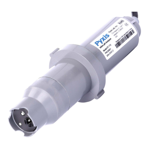
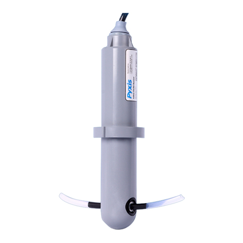
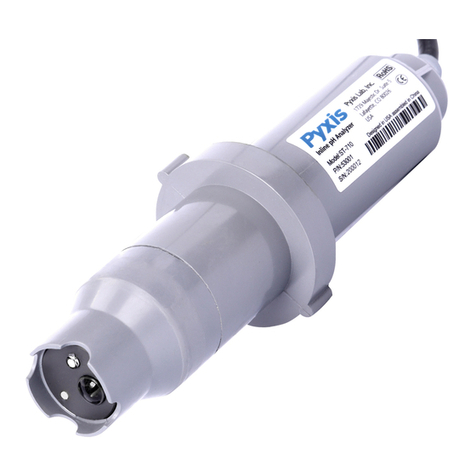
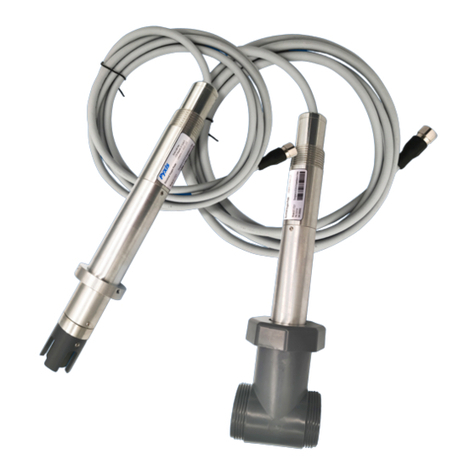
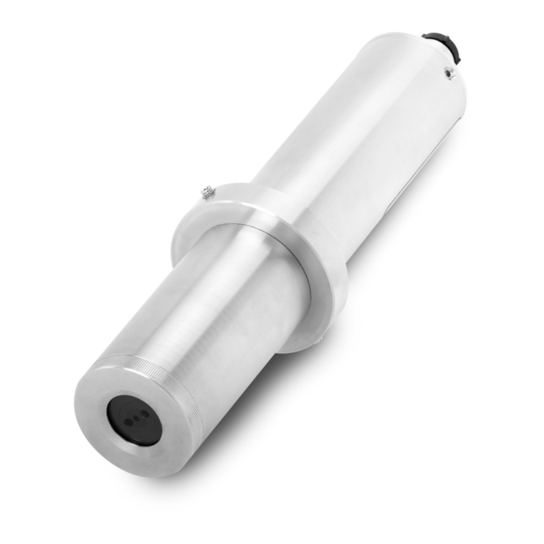
Pyxis ST-750 User manual

The information contained in this manual may be confidential and proprietary and is the property of Pyxis Lab, Inc.
Information disclosed herein shall not be used to manufacture, construct, or otherwise reproduce the goods
described. Information disclosed herein shall not be disclosed to others or made public in any manner without the
express written consent of Pyxis Lab, Inc.
Limited Warranty
Pyxis Lab warrants its products for defects in materials and workmanship. Pyxis Lab will, at its option, repair or
replace instrument components that prove to be defective with new or remanufactured components (i.e.,
equivalent to new). The warranty set forth is exclusive and no other warranty, whether written or oral, is expressed
or implied.
Device Warranty Term
The Pyxis warranty term for the ST-750 probe is thirteen (13) months from original shipment from Pyxis. In no event
shall the standard limited warranty coverage extend beyond thirteen (13) months from original shipment date.
Warranty Service
Damaged or dysfunctional instruments may be returned to Pyxis for repair or replacement. In some instances,
replacement instruments may be available for short duration loan or lease.
Pyxis warrants that any labor services provided shall conform to the reasonable standards of technical competency
and performance effective at the time of delivery. All service interventions are to be reviewed and authorized as
correct and complete at the completion of the service by a customer representative or designate. Pyxis warrants
these services for 30 days after the authorization and will correct any qualifying deficiency in labor provided that the
labor service deficiency is exactly related to the originating event. No other remedy, other than the provision of labor
services, may be applicable.
Repair components (parts and materials), but not consumables, provided in the course of a repair, or purchased
individually, are warranted for 90 days ex-works for materials and workmanship. In no event will the incorporation
of a warranted repair component into an instrument extend the whole instrument’s warranty beyond its original
term.
Warranty Shipping
A Repair Authorization Number (RA) must be obtained from Pyxis Technical Support before any product can be
returned to the factory. Pyxis will pay freight charges to ship replacement or repaired products back to the customer.
The customer shall pay freight charges for returning products to Pyxis. Any product returned to the factory without
an RA number will be returned to the customer.
Pyxis Technical Support

Pyxis ST-750 Operation Manual 3
Table of Contents
1Introduction ...............................................................................................................................4
1.1 Features of the Pyxis ST-750.........................................................................................................4
1.2 Specifications ................................................................................................................................5
1.3 Un-packing Instrument .................................................................................................................5
1.4 Standard Accessories ....................................................................................................................6
1.5 Optional Accessories.....................................................................................................................7
2Installation.................................................................................................................................8
3Quick 4-20mA Start.....................................................................................................................9
4Calibration and Diagnosis..........................................................................................................10
4.1 Calibration and Diagnosis with uPyxis Desktop App...................................................................10
4.1.1 Calibration...........................................................................................................................13
4.1.2 4-20mA Span Settings.........................................................................................................14
4.1.3 Diagnosis .............................................................................................................................14
4.2 Calibration through the Controller .............................................................................................15
5Modbus RTU.............................................................................................................................15
6Probe Cleaning and Maintenance..............................................................................................16
6.1 Cleaning Procedure.....................................................................................................................16
6.2 Other Common Troubleshooting Issues .....................................................................................17

Pyxis ST-750 Operation Manual 4
1Introduction
Product Description
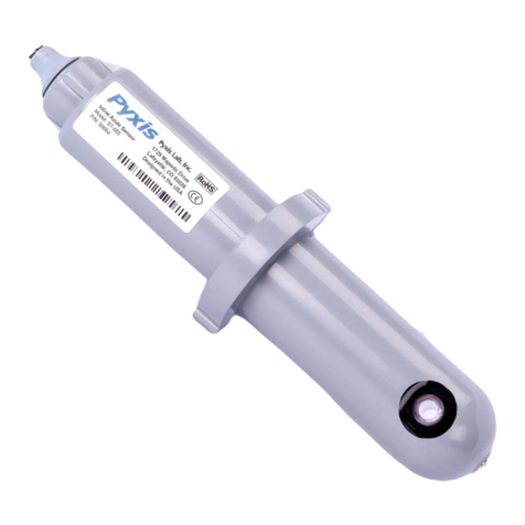
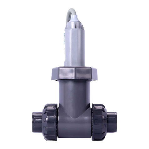
The Pyxis ST-750 inline APHA (Hazen) color sensor is uniquely designed to measure the real-time color in
water for use in municipal, industrial and environmental applications. The sensor uses the APHA-Hazen
platinum-cobalt (also referred to as Chromaticity) method to measure the color in the sample water and
is ideally suitable for clean water and lightly polluted water with a slight to pale yellow tint. This includes
relatively clean surface water, groundwater, domestic/drinking water and industrial water. The ST-750
has a built-in primary light source and detector to measure the color content, in addition a built-in
reference light source and detector are installed to compensate for mild levels turbidity interference.
The ST-750 offers a combination of fully integrated 4-20mA as well as RS-485 Modbus output signals and
is Bluetooth® 5.0 Enabled for wireless cleaning and calibration when used with MA-WB or PowerPACK
Series Bluetooth Adapters and the uPyxis APP for Desktop devices. The ST-750 is provided in UPVC with
the standard Pyxis ST-001 inline ¾-inch FNPT Tee assembly, 1.5-meter bulk-head cable with quick adapter
and 1.5-meter flying lead cable with quick adapter, enabling rapid wiring to any microprocessor
controller, PLC or DCS system.
Figure 1 - ST-750 Color Sensor with ST-001 Inline Tee Assembly

Pyxis ST-750 Operation Manual 5
1.1 Features of the Pyxis ST-750
The ST-750 probes include the following features:
•The probe can be conveniently installed in a bypass flow line using the ¾ inch inline Tee (ST-001)
assembly provided.
•ST-750 offers both 4-20mA and RS-485 outputs via 7-pin cable with adapters.
•The probe can be calibrated using a known COLOR concentration standard with the uPyxis
Desktop APP via a MA-WB Bluetooth/USB adapter (for sensors) and a USB-C cable connected
directly to the PC/Laptop. See section 4.1.
•The probe can be diagnosed via the uPyxis Desktop APP
1.2 Specifications
Specifications are subject to change without notice. Contact Pyxis (service@pyxis-lab.com) for an
updated specification list.
*NOTE* -With constant R&D at Pyxis Lab, specifications may be subject to change without notice.
Item
ST-750
P/N
53501
Target
APHA / Hazen / Platinum-Cobalt Color
Output Range
(4-20mA)
0.10-30.0 Degrees (ppm Pt-Co)
uPyxis APP Adjustable up to 500 Degrees Maximum
Lower Detect Limit
0.10 Degrees
Resolution
0.01 Degrees
Accuracy
±2% of reading or 0.1 Degrees, whichever is greater
Methodology
Platinum-Cobalt Color / APHA Color / Hazen Color / Wavelength 365nm
Power Supply
24 (±2) VDC, 65 mA
Outputs
Isolated 4-20mA Analog Output
Isolated RS-485 Digital Output, Supporting MODBUS protocol
Dimension
Length 6.8 inch (172.7 mm), body diameter 1.44 Inch (36.6 mm)
Weight
170 g (0.37lbs)
Installation
ST-001 Inline Tee ¾-inch FNPT with unions (Provided with each sensor)
Material
UPVC
Pressure
100 psi (6.9 Bar)
Temperature
4 °C - 40 °C (40 - 104 °F) Operating
-7 °C - 60 °C (20 - 140 °F) Storage
Cable Length
1.5m –7Pin Bulkhead Cable w/ IP67 Adapter
1.5m –7Pin Flying Lead Cable w/IP67 Adapter
Optional Extension Cables Available
Calibration
Two-point calibration against DI water and known COLOR Standards
Rating
IP67
Regulation
CE / RoHS
Method Compliance
ASTM-D1209 / ISO-6271

Pyxis ST-750 Operation Manual 6
1.3 Un-packing Instrument
Remove the instrument and accessories from the shipping container and inspect each item for any
damage that may have occurred during shipping. Verify that all accessory items are included. If any
1.4 Standard Accessories
•ST-001 Tee Assembly ¾-inch FNPT with Union / Thread & Socket (1x Tee, O-ring, and Nut)
•Bulkhead Cable (1.5m / 7Pin Cable w/Adapters)
•Flying Lead Cable (1.5m / 7Pin Cable w/Adapters)
1.4.1 Calibration Standard Solution
*NOTE* - Calibration Standard Solution must be Purchased Separately
Figure 2 - COLOR-30 Calibration Std
Item
COLOR-30
APHA Hazen Calibration Standard Solution
For use with ST-750 Sensor
Part Number
58000
Concentration
30 Degrees (ppm Pt-Co)
Form
Platinum / Cobalt –APHA Hazen
Shelf Life
6 months
Container
16 oz/500mL Nalgene Amber Narrow
Mouth Sample Bottle
Volume (net)
510 +/- 10mL
Weight (net)
510g +/- 10g

Pyxis ST-750 Operation Manual 7
1.5 Optional Accessories
Optional Accessories Information P/N
ST-001 Inline Tee Assembly Spare (3/4- inch FNPT Inline Tee Assembly) 50704
COLOR-30 (Color Calibration Standard 30 Degree / 500mL) 58000
Pyxis Probe Cleaning Kit (Includes Sensor Cleaner 500mL + Accessories) SER-01
MA-WB Bluetooth/USB Adapter (Pyxis Bluetooth/USB Adapter for 7Pin Pyxis Sensors) MA-WB
PowerPACK-1 (Single Chanel Auxiliary Power Supply w/Bluetooth For Pyxis Sensors) MA-BLE-1
PowerPACK-4 (Four Chanel Auxiliary Power Supply w/Bluetooth For Pyxis Sensors) MA-BLE-4
MA-C10 (10’ Extension Cable for 7Pin Pyxis Sensors) 50738
MA-C50 (50’ Extension Cable for 7Pin Pyxis Sensors) 50705

Pyxis ST-750 Operation Manual 8
2Installation
PRIMARY INSTALLATION FORMAT
The recommended installation method for ST-750 should be a bypass flow arrangement in a vertical
line to eliminate air bubble interference. This can be done with the standard ST-001 Inline Tee
Assembly (3/4-inch FNPT) provided with each sensor. The sensor will function in stagnant water
conditions and as high as 8-gpm maximum flow while installed in the ST-001 inline tee assembly.
During installation, it is suggested that isolation valves upstream and downstream of the sensor be
installed to allow flow regulation for optimum sensor accuracy, as well as for sensor removal, cleaning
and calibration. Pyxis also offers 2-inch, 3-inch and 4-inch inline tee assemblies. For alternative inline
Figure 3 - ST-750 Probe / ST-001 Inline Tee Assembly Diagram

Pyxis ST-750 Operation Manual 9
3Quick 4-20mA Start
Follow the wiring table below to connect the ST-750 probe to a receiving controller. *IMPORTANT NOTE*
there are two wiring tables for sensors. The Green and White wires (4-20mA values) are different between
each table. Listed above each table the specific serial # roll in representing when this change occurred.
Wiring Table for Sensors BEFORE Serial # - 210011
Wire Color
Designation
Red
24 V +
Black
Power Ground
White
Not Used
Green
4-20 mA for COLOR
Blue
RS-485 A
Yellow
RS-485 B
Clear
Shield, Solution ground
4mA Value
0.1 Degrees (ppm Pt-Co)
20mA Value
30.0 Deg
Wiring Table for Sensors INCLUDING and AFTER Serial # - 210011
Wire Color
Designation
Red
24 V +
Black
Power Ground
White
4-20 mA for COLOR
Green
Not Used
Blue
RS-485 A
Yellow
RS-485 B
Clear
Shield, Solution ground
4mA Value
0.1 Degrees (ppm Pt-Co)
20mA Value
30.0 Degrees (ppm Pt-Co)
*NOTE*: The 24V power ground and the 4-20 mA- return are internally connected. If insufficient wattage is available
from the connected controller (ie. 1.5-1.6W), Pyxis recommends the PowerPACK Series Auxiliary Power & Bluetooth
Communication Adapters highlighted in the Optional Accessories section of this manual. If a separate DC power
supply other than that from the controller is used, make sure that the output from the power supply is rated for 22-
26 VDC @ 65mA. Detailed wiring diagrams for common controllers are available from www.pyxis-lab.com.

Pyxis ST-750 Operation Manual 10
4Calibration and Diagnosis
The ST-750 probe can becalibrated in a two-point (zero + slope) procedure using adeionized water sample
and a standard solution containing a known COLOR standard solution. For ST-750, Pyxis recommends 30
deg COLOR calibration standard with Platinum/Cobalt formulation. Pyxis item COLOR-30 (P/N 58000).
4.1 Calibration and Diagnosis with uPyxis Desktop App
1) Download and install uPyxis Desktop APP from
https://upyxis.pyxis-lab.com.cn/release/pc/uPyxis.Setup-latest.zip
2) Connect a USB Type-C cable to the port at the bottom of the MA-WB and to the USB port of the laptop or
computer. This will provide power the MA-WB from the laptop/computer. Connect the MA-WB to the ST-
750 sensor. The MA-WB Bluetooth adapter will boost the 5V of the regular USB to 24V to power the sensor
for use with uPyxis Desktop.
Figure 5 - ST-750 Probe / MA-WB / USB-C Cable connected to uPyxis Desktop
Figure 4 - MA-WB Bluetooth Adapter –Bottom USB-C Port

Pyxis ST-750 Operation Manual 11
3) Set the MA-CR to operate in USB Mode by following the steps below.
a. Once the MA-CR screen is powered Press or until you arrive at (USB to RS485) screen.
b. Press the Button.
c. Follow Prompts below to Enable USB feature. Once enabled, you may connect to uPyxis.
4) Open the desktop uPyxis APP.
5) Click Device to launch the connection option menu.
6) Select Connect via USB-RS485 (Figure 6).
7) Select the Comm Port to make a connection. Normally only one Comm port is identified by uPyxis. If more
than one Comm port listed in the selection dropdown, you may try to select each one to see if a connection
can be made. Alternatively, you may use the Windows Device Manager to identify the Comm Port that the
Pyxis USB adapter is using.
Figure 6. Connect to ST-750 via USB-Bluetooth option

Pyxis ST-750 Operation Manual 12
After the connection is established, the ST-750 probe series number and current COLOR reading are
displayed on the left of the information page (Figure 7). In this page, a nickname can be assigned to the
probe. The probe Modbus address can be changed in this page.
Figure 7 - Connected to a ST-750 probe and information page
Figure 8 - Calibration Page

Pyxis ST-750 Operation Manual 13
4.1.1 Calibration
Click Calibration to launch the calibration page (Figure 9). Place the probe in deionized water and click
Zero Calibration to start the zero-point calibration.
Figure 9 - Zero Calibration
Place the probe in a known COLOR calibration solution and click Slope Calibration to start the slope
calibration. Enter the COLOR concentration in the dialog window as in Figure 10.
Figure 10 - Slope Calibration

Pyxis ST-750 Operation Manual 14
4.1.2 4-20mA Span Settings
The default 4-20mA span is 20 mA = 500 deg and 4 mA = 0.1 deg. Users may alter the output scale using
4-20mA Span to change the COLOR value corresponding to the 20mA output (Figure 11). *NOTE* the
20mA value span adjustment may only be equal to or lower than the upper range detection limit of the
sensor.
Figure 11 - Set 4-20mA Span
4.1.3 Diagnosis
Click Diagnosis to display the diagnosis page (Figures 12). In this page, the raw data measured by the
probe is displayed. To help troubleshoot possible issues with the probe, please save an image of this page
when the probe is placed in a clean water (tap water or deionized water), in a standard, and in the sample
that the probe is intended.
Figure 12 - Diagnosis Page

Pyxis ST-750 Operation Manual 15
4.2 Calibration through the Controller
It is recommended that ST-750 calibration is carried out using the uPyxis app as demonstrated in the
sections above. Alternatively, a single point calibration can be carried on the receiving controller by
adjusting the mA-to-deg COLOR ratio. A two-point calibration could also be carried out on the controller
by adjusting both the mA-to- deg COLOR ratio and the zero-point 4-20mA current value. Please follow the
controller manufacturer’s procedure to carry the 4-20mA calibration. With the default probe settings, the
controller should be set up to convert 4 mA = 0.1 deg and 20 mA = 30.0 deg for ST-750. It is critical that
the sensor optical channel be properly cleaned prior to sensor calibration. Please refer to Section 6.0 for
proper cleaning procedures.
5Modbus RTU
The ST-750 probes are configured as a Modbus slave device. In addition to the COLOR value, many
operational parameters, including warning and error messages, are available via a Modbus RTU
connection.

Pyxis ST-750 Operation Manual 16
6Probe Cleaning and Maintenance
The ST-750 probes are designed to provide reliable and continuous COLOR concentration readings even
when installed in moderately contaminated samples. Although the optics are compensated for the effects
of moderate fouling, heavy fouling will prevent the light from reaching the sensor, resulting in false
readings.
The ST-750 probes are designed to be easily removed, inspected and cleaned if required. It is suggested
that the ST-750 probes be checked for fouling and cleaned/calibrated on a monthly basis. Heavily
contaminated samples may require more frequent cleanings.
6.1 Cleaning Procedure
A light deposit inside the probe quartz tube can be cleaned by a Q-tip. Aged heavy deposition, especially
carbonate and iron oxide deposits, can be removed using a cleaning solution that is capable of removing
these inorganics, such as the Pyxis Probe Cleaning Solution Kit (P/N SER-01) available from Pyxis online
EStore Inline Sensor Cleaning Kit | Pyxis Lab® (pyxis-lab.com).
Soak the lower half of the ST-750 probe in 100 mL probe cleaning solution for 10 minutes. Scrub the
internal surfaces of the quartz optical channel aggressively with the pipe-cleaner brush and Q-tip provided
with the kit. Allow the sensor to soak in the cleaning solution for an additional 5-10 minutes. Remove and
rinse the ST-750 probe with distilled water or clean tap water and then check for the flashing blue light
inside the ST-750 probe quartz tube. If the surface is not entirely clean, continue to soak the ST-750 probe
for an additional 10 minutes or until clean. Repeat as needed.
Figure 13 –Pyxis Probe Cleaning Kit (P/N –SER-01)

Pyxis ST-750 Operation Manual 17
6.2 Other Common Troubleshooting Issues
If the ST-750 probe output signal is not stable and fluctuates significantly, make an additional solution
ground connection - connect the clear solution ground wire to a conductor that contacts the sample
water electrically such as a brass pipe near the ST-750 probe.
Contact us
Contact us if you have questions about the use or maintenance of the ST-750 probe:
Pyxis Lab, Inc.
1729 Majestic Dr. Suite 5
Lafayette, CO 80026 USA
1-866-203-8397
www.pyxis-lab.com
service@pyxis-lab.com
Table of contents
Other Pyxis Accessories manuals

Pyxis
Pyxis ST-774 User manual

Pyxis
Pyxis ST-710 User manual

Pyxis
Pyxis LS-200 Troubleshooting guide

Pyxis
Pyxis ST-565 User manual

Pyxis
Pyxis ST-540 Series User manual

Pyxis
Pyxis ST-772 User manual

Pyxis
Pyxis LS-202 User manual

Pyxis
Pyxis ST-588 User manual

Pyxis
Pyxis LS-200 User manual

Pyxis
Pyxis ST-730 Series User manual

Pyxis
Pyxis ST-525 User manual

Pyxis
Pyxis LSP Series User manual

Pyxis
Pyxis LT-635 User manual

Pyxis
Pyxis ST-772 User manual

Pyxis
Pyxis ST-590 Series User manual

Pyxis
Pyxis ST-500 User manual

Pyxis
Pyxis ST-601 User manual

Pyxis
Pyxis LS-200 User manual

Pyxis
Pyxis ST-773 User manual

Pyxis
Pyxis CR Series User manual