Pyxis LT-635 User manual

service@pyxis-lab.com | +1 (866) 203-8397
Pyxis LT-635 Series User Manual
1
Warranty Information
Confidentiality
The information contained in this manual may be confidential and proprietary and is the property of Pyxis
Lab, Inc. Information disclosed herein shall not be used to manufacture, construct, or otherwise reproduce
the goods described. Information disclosed herein shall not be disclosed to others or made public in any
manner without the express written consent of Pyxis Lab, Inc.
Standard Limited Warranty
Pyxis Lab warrants its products for defects in materials and workmanship.
Pyxis Lab will, at its option, repair
or replace instrument components that prove to be defective with new or remanufactured components
(i.e., equivalent to new).
The warranty set forth is exclusive and no other warranty, whether written or oral,
is expressed or implied.
Warranty Term
The Pyxis warranty term is thirteen (13) months ex-works. In no event shall the standard limited warranty
coverage extend beyond thirteen (13) months from original shipment date.
Warranty Service
Damaged or dysfunctional instruments may be returned to Pyxis for repair or replacement. In some in-
stances, replacement instruments may be available for short duration loan or lease.
Pyxis warrants that any labor services provided shall conform to the reasonable standards of technical
competency and performance effective at the time of delivery. All service interventions are to be reviewed
and authorized as correct and complete at the completion of the service by a customer representative or
designate. Pyxis warrants these services for 30 days after the authorization and will correct any qualifying
deficiency in labor provided that the labor service deficiency is exactly related to the originating event. No
other remedy, other than the provision of labor services, may be applicable.
Repair components (parts and materials), but not consumables, provided during a repair, or purchased
individually, are warranted for 90 days ex-works for materials and workmanship. In no event will the in-
corporation of a warranted repair component into an instrument extend the whole instrument’s warranty
beyond its original term.
Warranty Shipping
A Repair Authorization (RA) Number must be obtained from Pyxis Technical Support before any product can
be returned to the factory. Pyxis will pay freight charges to ship replacement or repaired products to the
customer. The customer shall pay freight charges for returning products to Pyxis. Any product returned to
the factory without an RA number will be returned to the customer. To receive an RMA you can generate a
request on our website at https://www.pyxis-lab.com/request-return-or-repair/
Pyxis Technical Support
Contact Pyxis Technical Support at +1 (866) 203-8397 or service@pyxis-lab.com
service@pyxis-lab.com | +1 (866) 203-8397
Pyxis LT-635 User Manual
2
Table of Contents
1Introducing the Pyxis LT-635 Sensor..................................................................................................3
1.1 Features of the Pyxis LT-635...........................................................................................................3
1.2 Specifications .................................................................................................................................4
1.3 Unpacking the Pyxis LT-635 Series Sensor......................................................................................4
1.4 Standard Accessories......................................................................................................................5
1.5 Optional Accessories......................................................................................................................5
2Quick 4-20mA Start .....................................................................................................................6
3Installation .................................................................................................................................7
4Calibration and Diagnosis ............................................................................................................9
4.1 Calibration and Diagnosis by uPyxis Mobile APP............................................................................9
4.1.1 Calibration by uPyxis Mobile APP.........................................................................................10
4.1.2 Restore to factory ................................................................................................................12
4.1.3 Diagnosis ..............................................................................................................................13
4.1.4 Cleaning Period Adjustment.................................................................................................14
4.2 Calibration and Diagnosis by uPyxis Desktop
APP
........................................................................ 15
4.2.1 Calibration............................................................................................................................17
4.2.2 Restore to Factory................................................................................................................19
4.2.3 Diagnosis ..............................................................................................................................20
5Modbus RTU.............................................................................................................................20
6Sensor Cleaning and Maintenance ............................................................................................21
7Sensor Wiper Replacement
Instructions
......................................................................................22
8Contact Us................................................................................................................................23

service@pyxis-lab.com | +1 (866) 203-8397
Pyxis LT-635 User Manual
3
1
Introducing
the
Pyxis
LT-635
Sensor
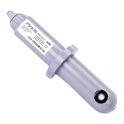
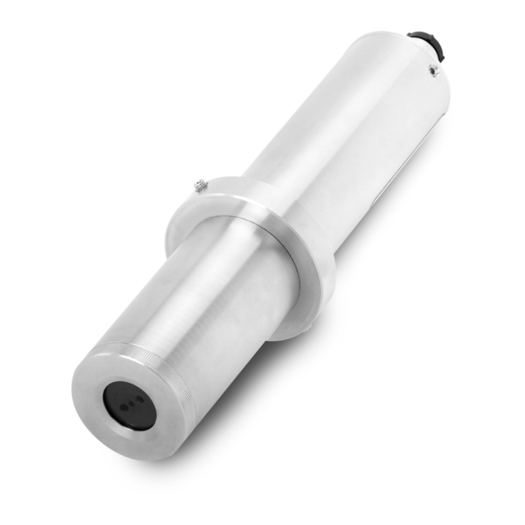
The LT-635 is a submersible, waterproof, self-cleaning sensor that determines the concentration of
suspended solids by measuring the attenuation of an infrared light source through the sample media.
The instrument is virtually maintenance-free, and the self-cleaning capability of the sensor prevents
deviations caused by air bubbles and sludge particulate. The LT-635 can be powered by a 24 VDC/6W
power supply and offers fully integrated 4-20 mA and RS-485 Modbus output signals for connection to
any controller, PLC or DCS network. When clean, the unique Pyxis sensor design offers a stability of
<0.1g/L for up to 1-year without calibration. Additionally, the LT-635 can be wirelessly accessed via the
MA-CR Bluetooth adapter for local display, diagnostics, cleaning, and calibration when using the uPyxis
APP for mobile or desktop devices. The LT-635 is ideal for use in wastewater applications including
clarifier/thickener sludge bed depth detection and activated aerobic or anoxic suspended solids
detection.
1.1 Features of the Pyxis LT-635
The LT-635 includes the following features:
•Resolution as low as 0.1g/L
•Built-in transmitter, without preamplifier or meter head
•Combination 4-20mA isolated signal and RS-485 Modbus (RTU) output
•Simple / Wireless calibration using uPyxis Mobile or Desktop APPs and MA-CR Bluetooth Adapter
•Supports self-cleaning of sensors
•Optional Ultrasonic Adapter for automatic cleaning (in development)
•Optional calibration with Pyxis secondary standards or field water samples
Figure 1 –LT-635 Dimensions (mm)

service@pyxis-lab.com | +1 (866) 203-8397
Pyxis LT-635 User Manual
4
1.2 Specifications
Item
LT-635
P/N
53251
Parameter
Suspended Solids / Total Suspended Solids
Measurement Range
0.00-30g/L (0.00 –30,000mg/L)
Unit
ppm (as SS or TSS)
Precision
± 0.1g/L or 5% of the value
Response Time
T95<10 Seconds
Calibration Method
Gravimetric Total Suspended Solids Analysis –Application Specific
Wavelength
850nm
Method
Absorbance
Power Supply
22 –26VDC 6W
Operating Temperature
32 –122 °F (0-50 °C)
Storage Temperature
-7 °C –60 °C (20 –140 °F)
Outputs
Isolated 4 –20 mA Analog Output & Isolated RS-485 Digital Output
Installation
Submersed –Fixed Conduit ¾-inch MPNT Threaded Cable Fitting
Submersed –Hoisting Chain or Cable
Material
316 Stainless Steel –Body & Wiper Arm
PTFE –Wiper Blade
Weight
1,530 g (3.3 lbs.)
Operational Pressure
45 psi (3.1 Bar)
Rating
IP-68, Fully Dustproof & Waterproof
Typical Wiper Life Span
12-18 Months (Avg. 10x/hour)
Regulation
CE / RoHS
Dimension (L x W x H)
(288mm x 57mm x 57mm)
Cable Length
33 feet (10m) w/IP-67 8-Pin adapter
4.9 feet (1.5m) flying lead w/IP-67 8-Pin adapter
*Pyxis Lab specifications are subject to change without notice
1.3 Unpacking the Pyxis LT-635 Series Sensor
Remove the instrument and accessories from the shipping container and inspect each item for any
damage that may have occurred during shipping. Verify that all items listed on the packing slip are
included. If any items are missing or damaged, please contact Pyxis Customer Service at service@pyxis-
lab.com

service@pyxis-lab.com | +1 (866) 203-8397
Pyxis LT-635 User Manual
5
1.4 Standard Accessories
The following accessories are included in the LT-635 sensor package (as shown in Error! Reference
source not found.):
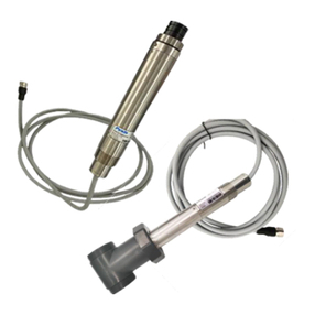
•One LT-635 sensor with bulkhead terminated cable w/8-Pin Female Adapter (33 feet / 10m)
•One MA-1.5CR Flying Lead Cable w/8-Pin Male Adapter/Flying Lead (4.9 feet / 1.5m)
•The full instrument manual is available for download at www.pyxis-lab.com/shop/
Figure 1 - LT-635 Sensor with 10m Terminated Cable + 1.5m Flying Lead Cable (MA-1.5CR)
1.5 Optional Accessories
Accessory Name
Item Number
LT-635 Replacement Wiper Blade/Arm Assembly Kit
(Includes 5 sets of Wiper Blade with Arm)
50700-A52
MA-CR
(Bluetooth Adapter/Display For use with Pyxis 8-Pin Sensors)
MA-CR
MA-NEB
(USB Bluetooth Adapter for use with Laptop or Desktop)
MA-NEB
UC-100A
(4 Sensor Pyxis Display/Data Logger RS-485/2x4-20mA/TCP)
43054
MA-120-C Fixed Submersion Adapter Bracket
(Submersed Fixed Installation Mounting Bracket)
50700-A11
MA-50CR (50’ Extension Cable w/8Pin Adapter)
50743
MA-100CR (100’ Extension Cable w/8Pin Adapter)
50744
Pyxis Sensor Cleaning Kit
SER-01

service@pyxis-lab.com | +1 (866) 203-8397
Pyxis LT-635 User Manual
6
2
Quick
4-20mA
Start
Follow the wiring table below to connect the LT-635 sensor to a controller or PLC. *NOTE* All Pyxis sensors
provide a passive 4-20mA output signal, they are NOT LOOP POWERED. 24VDC+ power supply and 4-
20mA+ signal are independent of each other in all Pyxis Lab sensors.
Color
Designation
Brown
Power GND
Green
RS-485 C
Yellow
RS-485 B
Gray*
4-20mA -
(Internally connected to power ground)
Pink
Not Used
Blue
RS-485 A
White
4-20mA + (TSS)
Red
24V+
Silver
PE
*NOTE* The 24V- power ground (brown) and the 4-20 mA- (gray) return are internally connected. If the
24V- power ground and the 4-20 mA return in the controller are internally connected (non-isolated 4-20mA
input), it is unnecessary to connect the 4-20 mA- (gray wire) to the 4-20 mA negative terminal in the
controller. If a separate DC power supplier other than that from the controller is used, make sure that the
output from the power supply is rated for 22-26 VDC @ 250mA.
Please refer to the table below for proper LT-635 input 4-20mA scaling in your receiving display, controller,
or PLC.
LT-635 Output Scaling (4-20mA)
mA
Value
Units
4
0
g/L
20
30
g/L

service@pyxis-lab.com | +1 (866) 203-8397
Pyxis LT-635 User Manual
7
3
Installation
Submersed Fixed Installation with MA-120-C: The LT-635 may be installed in a submersed/fixed
application using the MA-120-C Submersion Adapter Mounting Bracket (P/N: 50700A11). The LT-635
sensor should be installed as outlined in Figure 2 and 2A. For installation, the MA-120-C bracket
should permanently mounted in a fixed position for easy access to the LT-635 sensor and piping.
For sensor replacement and maintenance, users only need to lift (vertically/upwards) the sliding
block and conduit with the mounted sensor from MA-120-C bracket. Please note the LT-635
outer diameter is ¾ - inch NPT. A ¾ to 1-inch NPT bushing is required for installation.
Figure 2 –MA-120-C Submersion Adapter Mounting Bracket
MA-120-C
SS-304 Pipe (1-inch NPT)
Reducing Coupler (1-inch to 3/4 -inch FNPT
LT-635 ( ¾-inch MNPT
figure 2A - Installation Using MA-120-C Submersion Bracket with Piping

service@pyxis-lab.com | +1 (866) 203-8397
Pyxis LT-635 User Manual
8
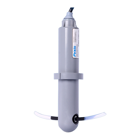
Submersed Installation with Lifting Ring: The LT-635 sensor comes equipped with a lifting ring which
allows the sensor to be lifted and lowered using a user provided chain or cable. This method of installation
enables use of the LT-635 in clarifier or thickener sludge bed depth profiling. Users may mark
measurement increments on the user provided lifting chain/cable and the LT-635 sensor may be slowly
lowered into the clarifier/thickener. When a drastic increase in suspended solids measurement is
observed, the sensor has been exposed to the clarifier/thickener sludge bed. The lowered distance of the
sensor to this observed TSS measurement change as indicated on the marked chain/cable can be used as
a reference of the clarifier/thickener supernatant (clean water). This value when subtracted from the total
clarifier/thickener height may be used as a reference to the sludge bed depth. For this method of
installation and use, please refer to Figure 3. For sensor replacement and maintenance, users only need
to lift the chain or cable and LT-635 Sensor vertically (upwards).
Lifting Ring
Figure 3 - Submersed Installation Using the Lifting Ring
Reference ID
Name
1
Retention Chain / Cable
2
Sensor Output Cable
3
LT-635 Suspended Solids Sensor
2
1
3

service@pyxis-lab.com | +1 (866) 203-8397
Pyxis LT-635 User Manual
9
4
Calibration
and
Diagnosis
The LT-635 suspended solids sensor is rigorously calibrated before leaving the
factory. As such, users do not need to calibrate the sensor for a period of one
year if the sensor is maintained clean. Users can however calibrate the sensor
according to their needs and as desired using the MA-CR Bluetooth adapter and
uPyxis APP for mobile or desktop devices. Likewise, the LT-635 may also be
calibrated after cleaning via PLC or controller through 4-20mA communication.
4.1 Calibration and Diagnosis by uPyxis Mobile APP
Connect and power the LT-635 sensor to a display, controller, or PLC. Insert the Pyxis MA-CR Bluetooth
adapter (P/N: MA-CR) as shown in the following connection diagram, using the 8-pin adapters on the
provided sensor cables. (Figure 4). The power should be sourced from a 24 VDC power terminal of the
connected display, controller, or PLC. If a controller is not available, the LT-635 may also be powered via
any 22-26 VDC power supply capable of 6W, that can directly connect to the LT-635 sensor with provided
connection cables from Pyxis. *NOTE* The MA-CR provides a micro-display for local visibility of the sensor
reading and mA value output.
Figure 4 - LT-635 and MA-CR Bluetooth Adapter Powered By Connected Display, Controller or PLC
Download and install the uPyxis APP from Apple Store or Google Play per the QR codes provided in the
image above. Be sure to turn on Bluetooth in the mobile device (please do not pair the device Bluetooth
to any Pyxis device, the uPyxis APP will do the pairing). Open the uPyxis APP in the mobile device. Finger
swipe the screen downward to refresh the screen and scan for the available Pyxis Bluetooth devices. The
discovered devices will be listed (see Figure 6).

service@pyxis-lab.com | +1 (866) 203-8397
Pyxis LT-635 User Manual
10
Figure
6
Figure
7
Tap the discovered LT-635 series sensor to connect to it via Bluetooth. The uPyxis APP can identify the
sensor type if multiple Pyxis sensors are discovered in the scan.
As shown in Figure7, when connected via the MA-CR Bluetooth adapter, the uPyxis calibration page will
display the current suspended solids concentration value being measured by the LT-635 sensor connected.
Four functional tabs are available in this page: Deionized Water Calibration, Mid-Range Calibration, High-
Range Calibration and Restore to Factory.
4.1.1 Calibration by uPyxis Mobile APP
Deionized Water Calibration Process - Remove the LT-635 sensor and rinse it thoroughly with deionized
water. Repeat this rinse process three times. Wipe the sensor with a dust-free cloth or paper-towel to
confirm that the sensor is free of obvious impurities. Insert the sensor into a beaker. Inject bubble-free
deionized water into the beaker and wait for the sensor reading to stabilize. Click the “Deionized Water
Calibration” button after the reading stabilizes. If the calibration is successful, the interface will return a
message "Calibration Succeeded" as shown in Figure 9. If the calibration has failed, the interface will
return a message "Calibration Failed", as shown in Figure 10 and the user must repeat the process until
calibration success is achieved.

service@pyxis-lab.com | +1 (866) 203-8397
Pyxis LT-635 User Manual
11
Figure
8
Figure
9
Figure
10
Mid-Range Calibration Process –After completing Deionized Water Calibration, remove and insert the LT-
635 sensor into a clean and dry beaker and inject the midpoint calibration solution. *NOTE* The midpoint
calibration solution can be process water of the application itself, with a verified Total Suspended Solids
(TSS) value in the range of 2,000 to 10,000 mg/L. The recommended method of TSS verification for the
calibration solution being used is Gravimetric Total Suspended Solids determination. Wait until the reading
stabilizes and then click the Midpoint Calibration button to calibrate the midpoint, as shown in Figure 11.
If the calibration is successful, the interface will return a message "Calibration Succeeded". If the
calibration has failed, the interface will return a message "Calibration Failed" and the user must repeat
the process until calibration success is achieved.
High-Range Calibration Process - If the high range calibration is not required (>10,000mg/L), the user does
not need to calibrate the high range. To continue with the high range calibration after completing Mid-
Range calibration, remove and insert the LT-635 sensor into a clean and dry beaker and inject the High
Point calibration solution. *NOTE* The high point calibration solution can be process water of the
application itself, with a verified Total Suspended Solids (TSS) value in the range of 10,000 to 30,000 mg/L.
The recommended method of TSS verification for the calibration solution being used is Gravimetric Total
Suspended Solids determination. Wait until the reading stabilizes and then click the High Point Calibration
button to calibrate the highpoint, as in Figure 12. If the calibration is successful, the interface will return
a message "Calibration Succeeded". If the calibration has failed, the interface will return a message
"Calibration Failed" and the user must repeat the process until calibration success is achieved.

service@pyxis-lab.com | +1 (866) 203-8397
Pyxis LT-635 User Manual
12
Figure
11
Figure
12
Trouble Shooting Steps for Failed Calibration Messages
oThe Deionized water has not been contaminated.
oThe standard solution is accurately pre-measured to verify Total Suspended Solids.
oThe sensor is clean and not contaminated with debris or other materials.
4.1.2 Restore to factory
Restore To Factory –If user wants to restore the sensor calibration to factory default parameters, as
shown in Figure13, click the OK option to confirm. If the restoration is successful, the interface will
return a message "Restore Succeed" (Figure 14).
Figure
13
Figure
14

service@pyxis-lab.com | +1 (866) 203-8397
Pyxis LT-635 User Manual
13
4.1.3 Diagnosis
Tap Diagnosis in the bottom of the APP page to launch the diagnosis page (Figure 15 ).
Figure 15 - Select Diagnosis for Sensor
Export/Upload Sensor Diagnosis Data - In this page, the raw data measured by the sensor is displayed. To
help troubleshooting possible issues with the sensor, please save images of these data when the sensor
is respectively placed in a clean water (tap water or deionized water), in a known Suspended Solids
Standard Solution and/or in the sample that the sensor is intended for. This data may be exported from

service@pyxis-lab.com | +1 (866) 203-8397
Pyxis LT-635 User Manual
14
4.1.4 Cleaning Period Adjustment
Tap Device info in the bottom of the uPyxis APP page to launch the Device info page (Figure 16). You can
set the Device Name, Product Name, Modbus Address and Brush Setting for the LT-635 sensor. Press
Brush Once to activate the wiper arm manually. Be sure to press Apply Settings to save any changes.
Figure 16 - Cleaning Period Adjustment

service@pyxis-lab.com | +1 (866) 203-8397
Pyxis LT-635 User Manual
15
4.2 Calibration and Diagnosis by uPyxis Desktop APP
Download and install uPyxis Desktop APP on your PC or Laptop from
https://upyxis.pyxis-lab.com.cn/release/pc/uPyxis.Setup-latest.zip
Connect and power the LT-635 sensor to a display, controller, or PLC. Insert the Pyxis MA-CR Bluetooth
adapter (P/N: MA-CR) as shown in the following connection diagram, using the 8-pin adapters on the
provided sensor cables. (Figure 17). Insert the MA-NEB Bluetooth USB adapter (P/N: MA-NEB) into the
USB port of your PC or Laptop according to connection diagram below (Figure 17).
Figure 17 - Connect the LT-635 to a computer via Pyxis MA-CR and MA-NEB adapter
Establish connection between uPyxis Desktop APP and the LT-635 through the following steps:
1. Open the desktop uPyxis Desktop APP on your PC or Laptop.
2. Click Device to launch the connection option menu.
3. Select Connect via USB-Bluetooth (Figure 18).
4. Select the Comm Port to make a connection (Figure 19) normally only one Comm port is identified
by uPyxis. If more than one Comm port listed in the selection dropdown, you may try to select
each one to see if a connection can be made. Alternatively, you may use the Windows Device
Manager to identify the Comm Port that the Pyxis USB adapter is used.
After the connection is established, the LT-635 sensor series number and current suspended solids
concentration reading of the water will be displayed on the left of the information page (Figure ). In
this page, you can set the Device Name, Product Name, Modbus Address and Brush Setting for the
device. Click Calibration to launch the calibration (Figure 21).

service@pyxis-lab.com | +1 (866) 203-8397
Pyxis LT-635 User Manual
17
Figure 21 - Calibration Page
4.2.1 Calibration
Deionized Water Calibration Process - Remove the LT-635 sensor and rinse it thoroughly with deionized
water. Repeat this rinse process three times. Wipe the sensor with a dust-free cloth or paper-towel to
confirm that the sensor is free of obvious impurities. Insert the sensor into a beaker. Inject bubble-free
deionized water into the beaker and wait for the sensor reading to stabilize. Click the “Deionized Water
Calibration” button after the reading stabilizes. If the calibration is successful, the interface will return a
message "Calibration Succeeded". If the calibration has failed, the interface will return a message
"Calibration Failed" and the user must repeat the process until calibration success is achieved.
Figure 22 - Deionized Water
Calibration

service@pyxis-lab.com | +1 (866) 203-8397
Pyxis LT-635 User Manual
18
Mid-Range Calibration Process –After completing Deionized Water Calibration, remove and insert the LT-
635 sensor into a clean and dry beaker and inject the midpoint calibration solution. *NOTE* The midpoint
calibration solution can be process water of the application itself, with a verified Total Suspended Solids
(TSS) value in the range of 2,000 to 10,000 mg/L. The recommended method of TSS verification for the
calibration solution being used is Gravimetric Total Suspended Solids determination. Wait until the reading
stabilizes and then click the Midpoint Calibration button to calibrate the midpoint, as shown in Figure 23.
If the calibration is successful, the interface will return a message "Calibration Succeeded". If the
calibration has failed, the interface will return a message "Calibration Failed" and the user must repeat
the process until calibration success is achieved.
Figure 23 - Mid-Range
High-Range Calibration Process - If the high range calibration is not required (>10,000mg/L), the user does
not need to calibrate the high range. To continue with the high range calibration after completing Mid-
Range calibration, remove and insert the LT-635 sensor into a clean and dry beaker and inject the High
Point calibration solution. *NOTE* The high point calibration solution can be process water of the
application itself, with a verified Total Suspended Solids (TSS) value in the range of 10,000 to 30,000 mg/L.
The recommended method of TSS verification for the calibration solution being used is Gravimetric Total
Suspended Solids determination. Wait until the reading stabilizes and then click the High Point Calibration
button to calibrate the highpoint, as in Figure 24. If the calibration is successful, the interface will return
a message "Calibration Succeeded". If the calibration has failed, the interface will return a message
"Calibration Failed" and the user must repeat the process until calibration success is achieved.
Calibration

service@pyxis-lab.com | +1 (866) 203-8397
Pyxis LT-635 User Manual
19
Figure 24 - High-Range
Trouble Shooting Steps for Failed Calibration Messages
oThe Deionized water has not been contaminated.
oThe standard solution is accurately pre-measured to verify Total Suspended Solids.
oThe sensor is clean and not contaminated with debris or other materials.
4.2.2 Restore to Factory
Restore To Factory –If user wants to restore the sensor calibration to factory default parameters,
as shown in Figure 25, click the OK option to confirm. If the restoration is successful, the interface
will return a message "Restore Succeed".
Figure 25 - Restore to Factory
Calibration
Table of contents
Other Pyxis Accessories manuals

Pyxis
Pyxis LS-202 User manual

Pyxis
Pyxis ST-772 User manual

Pyxis
Pyxis LS-200 User manual

Pyxis
Pyxis HM-500 Series User manual

Pyxis
Pyxis ST-750 User manual

Pyxis
Pyxis 53626 User manual

Pyxis
Pyxis ST-765SS Series User manual

Pyxis
Pyxis LSP-X01 Series User manual

Pyxis
Pyxis ST-590 Series User manual

Pyxis
Pyxis ST-600 User manual
Popular Accessories manuals by other brands

PEWA
PEWA Steinel IR 180 UP operating instructions

Oregon Scientific
Oregon Scientific THWR288 user manual

Pepperl+Fuchs
Pepperl+Fuchs UC4000-L2-E7-V15 quick start guide

Fluid
Fluid OASIS MOTORIZED MP3 MUSIC ISLAND user manual

AND
AND Weighing Indicator AD-4324 instruction manual

TOPPOINT
TOPPOINT LT91174 user manual