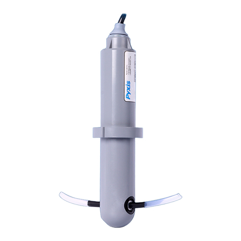
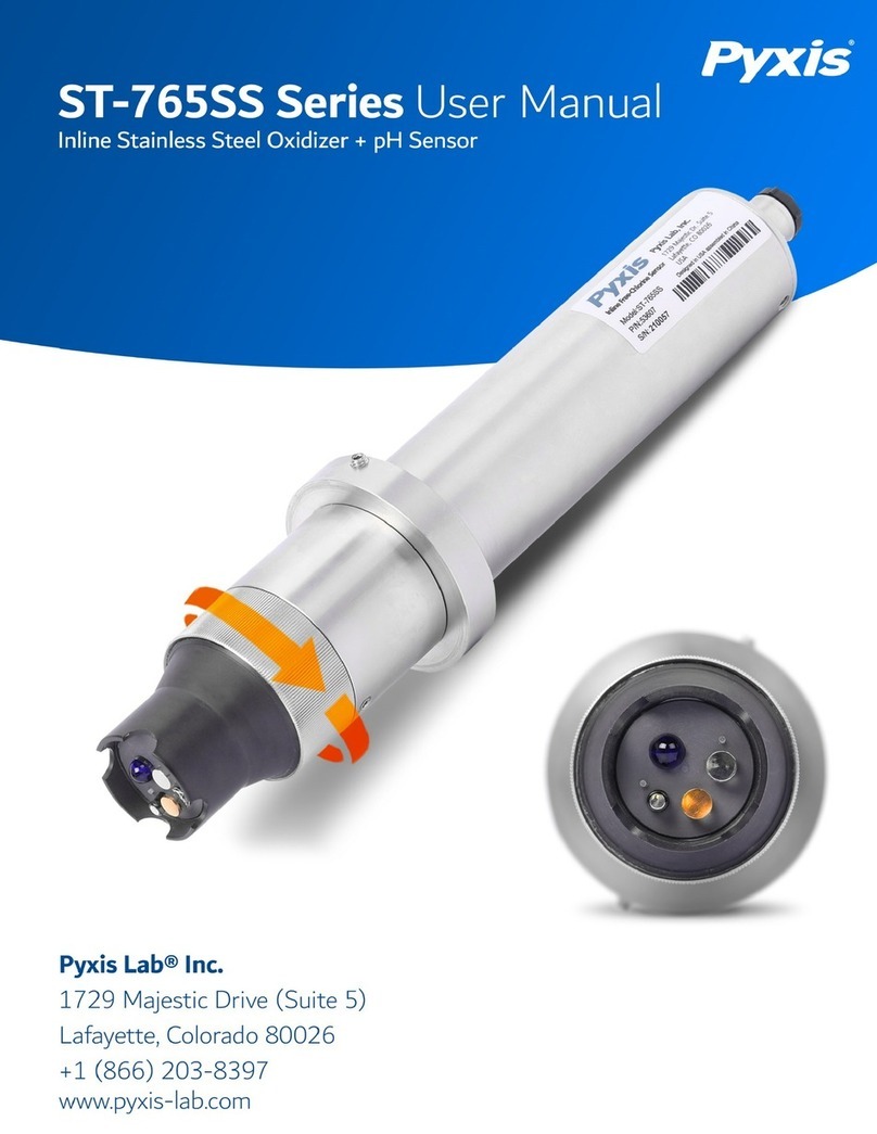
Pyxis ST-765SS-SO3 User manual

Table of Contents
1. Introducing the Pyxis ST-765SS-SO3 Sensor...................................................................3
1.2 Specifications.............................................................................................................4
1.3 Unpacking the Pyxis ST-765SS ...................................................................................4
1.4 Standard Accessories.................................................................................................5
1.5 Optional Accessories...............................................................................................5
2. Dimension & Installation...............................................................................................6
3. Quick 4-20mA Start Up..................................................................................................9
4. Calibration and Diagnosis...........................................................................................10
4.1 Calibration and Diagnosis by uPyxis Mobile App ...................................................10
4.1.1 Sulfite Calibration.............................................................................................................................................. 12
4.1.2 pH Calibration .............................................................................................................................................. 13
4.1.3 4-20mA Span................................................................................................................................................ 14
4.1.4 Diagnosis ...................................................................................................................................................... 14
4.2 Calibration and Diagnosis by uPyxis Desktop App .................................................15
4.2.1 Sulfite Calibration......................................................................................................................................... 18
4.2.2 pH Calibration.............................................................................................................................................. 18
4.2.3 4-20mA Span................................................................................................................................................ 20
5. Calibration on the Controller......................................................................................21
6. Modbus RTU...............................................................................................................21
7. Sensor Cleaning and Maintenance..............................................................................22
7.1 Other Common Troubleshooting Issues................................................................22
8.Replacing pH and Deoxidizer Electrode Head ..............................................................23
9. Contact Us ..................................................................................................................24

ST-765SS-O3 Sensor Manual
service@pyxis-lab.com | +1 (866) 203-8397
2
Warranty Information
Confidentiality
The information contained in this manual may be confidential and proprietary and is the property of
Pyxis Lab, Inc. Information disclosed herein shall not be used to manufacture, construct, or otherwise
reproduce the goods described. Information disclosed herein shall not be disclosed to others or made
public in any manner without the express written consent of Pyxis Lab, Inc.
Standard Limited Warranty
Pyxis Lab warrants its products for defects in materials and workmanship. Pyxis Lab will, at its option,
repair or replace instrument components that prove to be defective with new or remanufactured
components (i.e., equivalent to new). The warranty set forth is exclusive and no other warranty, whether
written ororal, is expressed or implied.
Warranty Term
The Pyxis warranty term for the ST-765SS Series sensor body is thirteen (13) months from original
shipment from Pyxis. The Pyxis warranty term for the EH-765 (electrode reference head) installed on the
ST-765SS Series sensor body is six (6) months from original shipment from Pyxis. In no event shall the
standard limited warranty coverage extend beyond this timeline from original shipment date.
Warranty Service
Damaged or dysfunctional instruments may be returned to Pyxis for repair or replacement. In some in-
stances, replacement instruments may be available for short duration loan or lease.
Pyxis warrants that any labor services provided shall conform to the reasonable standards of technical
com- petency and performance effective at the time of delivery. All service interventions are to be
reviewed and authorized as correct and complete at the completion of the service by a customer
representative, or des- ignate. Pyxis warrants these services for 30 days after the authorization and
will correct any qualifying deficiency in labor provided that the labor service deficiency is exactly related
to the originating event. No other remedy, other than the provision of labor services, may be applicable.
Repair components (parts and materials), but not consumables, provided during a repair, or purchased
individually, are warranted for 90 days ex-works for materials and workmanship. In no event will the in-
corporation of a warranted repair component into an instrument extend the whole instrument’s warranty
beyond its original term.
Warranty Shipping
A Repair Material Authorization (RMA) Number must be obtained from Pyxis Technical Support before any
product can be returned to the factory. Pyxis will pay freight charges to ship replacement or repaired
products to the customer. The customer shall pay freight charges for returning products to Pyxis. Any
product returned to the factory without an RA number will be returned to the customer. To receive an RMA
you can generate a request on our website at https://pyxis-lab.com/request-tech-support/.
Pyxis Technical Support
Contact Pyxis Technical Support at +1 (866) 203-8397, service@pyxis-lab.com or by filling out a request for
support at https://pyxis-lab.com/request-tech-support/.
ST-765SS-SO3 Sensor Manual
service@pyxis-lab.com | +1 (866) 203-8397
3
1. Introducing the Pyxis ST-765SS-SO3 Sensor
Description
The Pyxis ST-765SS-SO3 is a stainless-steel multi-parameter membrane-
less sensor based on unique electrochemical principles to determine
Sulfite plus pH and temperature of water. This sensor incorporates Pyxis'
advanced technology in the field of bare-gold electrochemical detection.
The ST-765SS-SO3 can simultaneously compensate for temperature and
pH in the measurement of Sulfite based on real-time conditions present in
the application of use. This unique internal compensation results in a
highly accurate sulfite measurement consistent with wet chemistry
methodology commonly used for measurement of oxygen or oxidizer
scavengers.
The ST-765SS-SO3 sensor offers a replaceable, front loading reference
electrode assembly that has been independently developed by Pyxis Lab
eliminating the shortcomings associated with membranes and gel
replacement while offering reduced polarization time on startup with an
electrode life span potential of up to 2-years. The flat front-end design of
the ST-765SS-SO3 makes this platform less prone to contamination or
fouling and is easy to clean. The ST-765SS-SO3 sensor body is composed
of 304 stainless steel and is well suited for aggressive environments.
The ST-765SS-SO3 sensor offers 2x 4-20mA and RS-485 Modbus outputs
and is Bluetooth 5.0 enabled when used in conjunction with the MA-CR
Bluetooth Adapter. This four-electrode composite sensor provides three
measured parameters including Sulfite, pH and temperature with one
sensor equipped with fully integrated 2x 4-20mA and RS-485 Modbus
outputs. ST-765SS-SO3 is uniquely designed for rapid and precise
monitoring of oxygen or oxidizer scavengers in water and process related
applications.
Key Features
•Real-Time pH + Sulfite (0-5ppm) Detection (uPyxis Adjustable to 100ppm Max)
•Dual 4-20mA Outputs (Sulfite + pH) and RS-485
•Bluetooth Enabled when used with MA-CR Adapter Wireless uPyxis Calibration
•Integrated RTD & pH Compensation to pH 9.0+ of the Sulfite Value
•Replaceable EH-765 Reference Electrode Assembly –Simple Maintenance
Common Applications
•RO Feedwater Chlorine Removal
•Wastewater Effluent Chlorine Removal (when used with FR-300-PLUS)
•Boiler Feedwater & Blowdown Oxygen Scavenger Monitoring
ST-765SS-SO3
Sulfite + pH Sensor
EH-765
Replacement Electrode
for all ST-765SS Series

ST-765SS-SO3 Sensor Manual
service@pyxis-lab.com | +1 (866) 203-8397
4
1.2 Specifications
Item
ST-765SS-SO3
P/N
53624
Sensor Body Material
304SS
Sulfite Standard Range
0.00-5.00 ppm Sulfite
(Factory Standard Range –Adjustable via uPyxis)
Sulfite Precision
± 0.01mg/L or 1% of the value w/pH compensation up to 9.0+
Sulfite Maximum Range
0-100 ppm Sulfite
(Adjustable via uPyxis 4-20mA SPAN ADJUST)
Sulfite Maximum Precision
± 1 mg/L or 1% when in MAX SPAN Mode
pH Range
0-14
pH Precision
±0.01 pH
Sample Inlet Pressure
7.25 –30 psi (0.05 –0.2MPa)
Installation
ST-007 Stainless Steel Flow Cell Assembly (Sold Separately)
ST-007 Minimum Flow Rate
200 mL/minute
ST-007 Maximum Flow Rate
400 mL/minute
ST-007 Sample Inlet
¼ - inch OD
ST-007 Sample Outlet
¼ - inch OD
Power Supply
22 –26VDC, Power Consumption 2W
Storage Temperature
-7 °C –60 °C (20 –140 °F)
Outputs
Dual Isolated 4 –20 mA Analog Outputs + Isolated RS-485 Digital Output
Dimension (L x D)
Length 8.3 inch (210.8 mm), body diameter 1.4 Inch (35.6 mm)
Weight
530 g (1.16lbs)
Maximum Sensor Pressure
100 psi (6.9 Bar) –Sensor Only
Operating Temperature
4 °C –49 °C (40 –120 °F)
Wet Material
UPVC
Rating
IP67, Fully Dustproof & Waterproof
Selectivity
Non-Selective / Cross Sensitive to other Reducing Species
Compliance
EPA 334.0 / ISO 7393
Regulation
CE Marked / RoHS
Cables Included
MA-4.9CR Cable (8Pin Adapter –4.9ft)
MA-1.5CR Cable (8 Pin Adapter / Flying Leads –1.5ft)
Typical Electrode Service Life
2 Years
Electrode Warranty
6 Months
Sensor Body Warranty
13 Months
*NOTE* Specifications are subject to change without notice.
1.3 Unpacking the Pyxis ST-765SS
Remove the instrument and accessories from the shipping container and inspect each item for any damage
that may have occurred during shipping. Verify that all items listed on the packing slip are included. If any

ST-765SS-SO3 Sensor Manual
service@pyxis-lab.com | +1 (866) 203-8397
5
1.4 Standard Accessories
•One ST-765SS-SO3 sensor (P/N: 53624)
•NOTE- The ST-007 Flow Tee Assembly must be purchased separately see below
•One MA.4.9CR –(Standard Cable Male-Female 8-Pin Adapters –4.9ft)
•One MA-1.5CR –(Flying Lead Cable Female/Flying Lead 8-Pin Adapter –1.5ft)
•The full instrument manual is available for download at Support Documents - Pyxis Lab, Inc.
(pyxis-lab.com)
1.5 Optional Accessories
The following optional accessories can be purchased separately via your preferred Pyxis Lab distributor or
Accessory Name
Item number
ST-007
(316L Stainless Steel Tee Assembly ¼-inch OD Compression)
50700-A51
EH-765
(Replacement Reference Electrode Head for ST-765SS Series)
53601
MA-CR
(Bluetooth Adapter For use with Pyxis 8-Pin Sensors)
MA-CR
MA-NEB
(USB Bluetooth Adapter for use with Laptop or Desktop for uPyxis)
MA-NEB
UC-80
(Display + Data Logging Terminal)
14003
MA-50CR
(Extension Cable-50 feet)
50743
pH4-7-10 Combination Pack - Reference Standard Solutions
(500mL/each)
57007
SP-200 OxiPocket
(Pocket All-Oxidizing Disinfectants Colorimeter & Fluorometer)
50802

ST-765SS-SO3 Sensor Manual
service@pyxis-lab.com | +1 (866) 203-8397
6
2. Dimension & Installation
The ST-765SS-SO3 should be installed in the ST-007 stainless steel inline sensor tee assembly for optimum
accuracy. Sulfite functions an oxygen and chlorine scavenger are highly susceptible to rapid degradation.
Stainless steel is recommended to ensure minimal sulfite depletion between injection of treatment and
the sensor. The ST-007 is provided with ¼-inch stainless steel OD inlet and outlet compression adapter
(SwageLok) and it is recommended that ¼-inch OD stainless steel tubing be utilized for sample flow. The
recommended flow rate for the ST-765SS-SO3 sensor in the ST-007 inline tee assembly is 200-400mL per
minute and should be controlled upstream with rotameter. The inlet water sample pressure should be
maintained between 7.5 and 30 psi with discharge to open drain or atmospheric sump.
ST-765SS-SO3 Dimensions (mm)
Figure 1. Dimension of the ST-765SS (mm)
ST-007 Flow Cell Dimensions (mm)
Figure 2. ST-007 Flow Cell Dimensions for ST-765SS Series Sensors

ST-765SS-SO3 Sensor Manual
service@pyxis-lab.com | +1 (866) 203-8397
7
IK-765SS-SO3 Sulfite + pH + Temperature Online Monitoring Panel as shown in Figure 3.
The IK-765SS-SO3 is a pre-assembled Sulfite + pH + Temperature monitoring panel consisting of the ST-765SS-
SO3 (Sulfite) sensor with mounted ST-007 stainless steel flow cell with rotameter and hall effect flow
meter, connected to the UC-80 Display + Data Logging Terminal. These platform solutions offer real-time
display, data logging and signal output capability of sample Sulfite, pH and temperature. The UC-80 is a
microprocessor display/data-logging terminal that has been preconfigured to connect Pyxis inline sensors
with fully integrated calibration, scaling and measurement protocol. When any Pyxis Lab sensor is connected
to the UC-80 in RS-485 Modbus, the UC-80 automatically recognizes the sensor and configuration for
immediate data display, data logging and communication. The user may also configure and calibrate the
output signal through the UC-80 controller's screen. *NOTE* For boiler feedwater and blowdown sulfite
measurement, the IK-765SS-SO3 panel must be installed downstream of a sample cooler.
Figure 3 IK-765SS-SO3 Panel (mm)
Item
P/N
Description
IK-765SS-SO3
42163
ST-765SS-SO3 Sensor + ST-007 Flow Cell + UC-80 Display/Data Logger

ST-765SS-SO3 Sensor Manual
service@pyxis-lab.com | +1 (866) 203-8397
8
Specifications of UC-80 Display/Data Logging Terminal
Dimensions of UC-80 (mm/in)
Item
UC-80
P/N
14003
Measurement Interval
Continuous Measurement
Display
4.3-inch LCD Color Industrial Capacitive Touch Screen
Storage Capacity
Built-In 128MB of Ram for Storing up to 1-Million Data/Event Records
Power Requirement
96-260VAC / 50-60 Hz; 200 W
Output
2 x 4-20 mA / RS-485 Modbus - RTU / Modbus TCP
Input
RS-485 Modbus - RTU
USB
1 x USB host, for data downloading and screen upgrade
Internet
RJ-45 socket, Modbus-TCP –For Pyxis CloudLinkTM
Panel Operational Temperature
40 –113oF (4-45 oC)
Storage Temperature
Instrument: -4 –131oF (-20 –55oC)
Sample Water Temperature
40 –104oF (4-40oC)
Rating
IP-65 Panel-Display
Regulation
CE / RoHS
Relative Humidity
20% - 90% (No Condensation)
Altitude
<6,561 feet (<2,000 Meter)
Dimensions (HxWxD)
H250×W150×D100mm
Approximate Product Weight
~ 5 kg

ST-765SS-SO3 Sensor Manual
service@pyxis-lab.com | +1 (866) 203-8397
9
3. Quick 4-20mA Start Up
Follow the wiring table below to connect the ST-765SS series sensor to a controller. *NOTE* The ST-
765SS-SO3 sensor comes preset at 0-5ppm range of measurement and output signal from the Pyxis factory.
This may be altered to a maximum of 100ppm using the 4-20mA SPAN ADJUST feature with the uPyxis APP.
Wire Color
Designation
Red
24 V +
Brown
Power Ground
Green
Shield, solution ground
Gray
4-20 mA -
White
4-20 mA+for Sulfite
Pink
4-20 mA + for pH
Blue
RS-485 A
Yellow
RS-485 B
Black
Shield, solution ground
ST-765SS-SO3 Sensor 4-20mA Scaling
Unit of Measure
4mA Value
20mA Value
pH
0.00 pH
14.00 pH
Sulfite
0.00 ppm
5.00 ppm
(Adjustable to 100ppm MAX)
*NOTE* If the 24V power ground and the 4-20 mA-return in the controller are internally connected (non-
isolated 4-20mA input), it is unnecessary to connect the 4-20 mA- (Gray wire) to the 4-20 mA negative terminal
in the controller. If a separate DC power supplier other than that from the controller is used, make sure that
the output from the power supply is rated for 22-26 VDC @ 85mA.

ST-765SS-SO3 Sensor Manual
service@pyxis-lab.com | +1 (866) 203-8397
10
4. Calibration and Diagnosis
The ST-765SS Series sensors are rigorously calibrated before leaving the factory. As such, users do not need
to calibrate the sensor for a period of three months or up to one year if the sensor is maintained in clean
condition. Users can however calibrate the sensor according to their application needs and as desired using
the MA-CR Bluetooth adapter and uPyxis APP for mobile or desktop devices.
4.1 Calibration and Diagnosis by uPyxis Mobile App
Connect and power the ST-765SS sensor using the MA-CR Pyxis Bluetooth adapter (P/N: MA-CR) as shown in
the following connection diagram. The power should be sourced from a 24 VDC power terminal of a
controller. If a controller is not available, please purchase a 24VDC power supply.
Figure 4. - Power the ST-765SS
and
MA-CR via USB
MA-CR Bluetooth Adapter

ST-765SS-SO3 Sensor Manual
service@pyxis-lab.com | +1 (866) 203-8397
11
Download and install the uPyxis app from Apple iStore or Google Play. Turn on the
Bluetooth in the smart device (please do not pair your device Bluetooth to uPyxis,
the app will do the pairing). Open the uPyxis app in the device. Swipe down to
refresh the screen to scan the available Pyxis Bluetooth devices. The discovered
devices will be listed as shown in Figure 6.
Tap the discovered ST-765SS sensor to connect to the sensor. The uPyxis app can
identify the sensor type if multiple Pyxis sensors are discovered in the scan.
As shown in Figure 6, in the calibration page of uPyxis after connected to the sensor via the MA-CR
Bluetooth adapter the current Sulfite, pH and temperature values will be displayed. Six functional tabs of each
are available in this page: Zero Calibration, Slope Calibration, pH Low Calibration, pH 7 Calibration, pH High
calibration and 4-20mA Span.
Figure 5 - ST-765SS discovered by Bluetooth scan Figure 6 - Calibration Page

ST-765SS-SO3 Sensor Manual
service@pyxis-lab.com | +1 (866) 203-8397
12
4.1.1 Sulfite Calibration
The measurement module of the ST-765SS-SO3 sensor is thoroughly calibrated at the Pyxis Lab factory using
an Argon saturated water sample containing a precise residual concentration of Sulfite. To field calibrate the
ST-765SS-SO3 sensor, the user can perform a single-point according to the requirements of the application.
Calibration of the ST-765SS-SO3 sensor for Sulfite should be done with the sensor inline exposed to active
flowing sample water. Use titration method, colorimeter or fluorometer (i.e.. Pyxis SP-800 / SP-910 or Hach
DR1300) to test the active (flowing) water sample in the flow tee assembly. Once you have tested and
confirmed the Sulfite concentration value in the active (flowing) flow tee assembly, Tap SLOPE CALIBRATION
and enter the test result value of the portable or laboratory colorimeter in Calibration Screen as shown in
Figure 7. *NOTE* For best results, the concentration of the Sulfite sample flow standard should be in the range
of the sensor 4-20mA output setup for the actual application.
Figure 7 -
Enter Sulfite concentration to begin slope calibration

ST-765SS-SO3 Sensor Manual
service@pyxis-lab.com | +1 (866) 203-8397
13
4.1.2 pH Calibration
Remove and place the sensor in a low pH (i.e.. 4.0) calibration standard solution and tap pH LOW
CALIBRATION in the uPyxis app. Measure for 1 minute and wait for the measurement result to stabilize before
performing calibration, the low pH calibration standard value range acceptable for this step is 1.00-6.00 pH.
Place the sensor into the pH 7.0 calibration standard solution and tap pH 7 CALIBRATION in the uPyxis app.
Measure for 1 minute and wait for the measurement result to stabilize before performing calibration.
Place the sensor in a high pH (i.e.. 10.0) calibration standard solution and tap pH HIGH CALIBRATION in the
uPyxis app. Measure for 1 minute and wait for the measurement result to stabilize before performing
calibration, the high pH calibration standard value range acceptable for this step is 8.00-13.00 pH.
Figure 8 Figure 9
Enter Low-pH Concentration for Calibration Enter High-pH Concentration for Calibration

ST-765SS-SO3 Sensor Manual
service@pyxis-lab.com | +1 (866) 203-8397
14
4.1.3 4-20mA Span
The 4–20mA output of the ST-765SS-SO3 sensor is scaled as:
•Sulfite:
–
4 mA = 0 ppm
–20 mA = 5 ppm
Tap 4-20mA SPAN to change the Sulfite value corresponding to the 20mA output to a value below 100ppm
as seen in Figure 9. *NOTE* The 4-20mA Span feature allows users to ADJUST the 20mA output scale to a
maximum value of 100ppm. You cannot INCREASE the upper limit of the sensor beyond the maximum
range of the sensor (100ppm).
Figure 10 - Enter Sulfite concentration to set 4-20mA Figure 11 - Diagnostic interface
4.1.4 Diagnosis
Tap Diagnosis in the bottom of the app page to launch the diagnosis page Figure 11.
In this page, the raw data measured by the sensor is displayed. To help troubleshooting possible issues with
the sensor, please save images of these data when the sensor is respectively placed in a clean water (tap
water or deionized water), in a Sulfite, or pH standard solution, and in the sample that the sensor is intended
for. This data may be exported from the uPyxis APP via email to service@pyxis-lab.com for technical support.

ST-765SS-SO3 Sensor Manual
service@pyxis-lab.com | +1 (866) 203-8397
15
4.2 Calibration and Diagnosis by uPyxis Desktop App
1) Download and install uPyxis Desktop APP from
https://upyxis.pyxis-lab.com.cn/release/pc/uPyxis.Setup-latest.zip
2) Connect a USB Type-C cable to the port at the bottom of the MA-CR and to the USB port of the laptop or
computer. This will provide power the MA-CR from the laptop/computer. Connect the MA-CR to the ST-765SS-
O3 sensor. The MA-CR Bluetooth adapter will boost the 5V of the regular USB to 24V to power the sensor for
use with uPyxis Desktop.
Figure 12 –MA-CR Connected to Sensor & Laptop
3) Set the MA-CR to operate in USB Mode by following the steps below.
a. Once the MA-CR screen is powered Press or until you arrive at (USB to
RS485) screen.
b. Press the Button.
c. Follow Prompts below to Enable USB feature. Once enabled, you may connect to uPyxis.
MA-CR Bluetooth Adapter –Bottom USB-C
Port

ST-765SS-SO3 Sensor Manual
service@pyxis-lab.com | +1 (866) 203-8397
16
4) Open the desktop uPyxis APP.
5) Click Device to launch the connection option menu.
6) Select Connect via USB-RS485 (Figure 13).
7) Select the Comm Port to make a connection. Normally only one Comm port is identified by
uPyxis (Figure 14). If more than one Comm port listed in the selection dropdown, you may try
to select each one to see if a connection can be made. Alternatively, you may use the
Windows Device Manager to identify the Comm Port that the Pyxis USB adapter is using.
After the connection is established, the ST-765SS sensor series number and Ozone reading will be displayed
on the left of the information page Figure 15. In this page, a nickname can be assigned to the sensor. The
sensor Modbus address can also be changed if desired. Click Calibration to launch the calibration page Figure
16.
Figure 13 - Connection Options

ST-765SS-SO3 Sensor Manual
service@pyxis-lab.com | +1 (866) 203-8397
18
4.2.1 Sulfite Calibration
The measurement module of the ST-765SS-SO3 sensor is thoroughly calibrated at the Pyxis Lab factory. To
calibrate, the user can perform a single-point according to the requirements of the application.
Calibration of the ST-765SS-SO3 sensor for Sulfite should be done with the sensor inline exposed to active
flowing sample water. Use a portable or laboratory colorimeter (i.e.. Pyxis SP-200 / SP-800 / SP-910 or similar)
to test the active (flowing) water sample in the flow tee assembly. Once you have tested and confirmed the
concentration value in the active (flowing) flow tee assembly, Tap SLOPE CALIBRATION and enter the test
result value of the portable or laboratory colorimeter in Calibration Screen as shown in Figure 17. *NOTE*
For best results, the concentration of the Sulfite sample flow standard should be in the range of the sensor 4-
20mA output setup for the actual application.
Figure 17 - Slope Calibration
4.2.2 pH Calibration
Remove and place the sensor in a low pH (i.e.. 4.0) calibration standard solution and tap pH LOW
CALIBRATION in the uPyxis app. Measure for 1 minute and wait for the measurement result to stabilize before
performing calibration, the low pH calibration standard value range acceptable for this step is
1.00-6.00 pH.
Place the sensor into the pH 7.0 calibration standard solution and tap pH 7 CALIBRATION in the uPyxis app.
Measure for 1 minute and wait for the measurement result to stabilize before performing calibration. Place the
sensor in a high pH (i.e.. 10.0) calibration standard solution and tap pH HIGH CALIBRATION in the uPyxis app.
Measure for 1 minute and wait for the measurement result to stabilize before performing calibration, the
high pH calibration standard value range acceptable for this step is 8.00-13.00 pH.
This manual suits for next models
1
Table of contents
Other Pyxis Accessories manuals

Pyxis
Pyxis ST-730 Series User manual

Pyxis
Pyxis ST-525 User manual

Pyxis
Pyxis LS-200 User manual

Pyxis
Pyxis ST-500W User manual

Pyxis
Pyxis ST-710 User manual

Pyxis
Pyxis LS-202 User manual

Pyxis
Pyxis LT-635 User manual

Pyxis
Pyxis ST-772 User manual

Pyxis
Pyxis LS-202 User manual

Pyxis
Pyxis ST-540 Series User manual

Pyxis
Pyxis LS-200 Troubleshooting guide

Pyxis
Pyxis LSP-X01 Series User manual

Pyxis
Pyxis ST-765SS Series User manual

Pyxis
Pyxis LT-73 Series User manual

Pyxis
Pyxis ST-500 User manual

Pyxis
Pyxis CR Series User manual

Pyxis
Pyxis ST-500 User manual

Pyxis
Pyxis LS-200 User manual

Pyxis
Pyxis ST-700 Series User manual

Pyxis
Pyxis LS-202 User manual