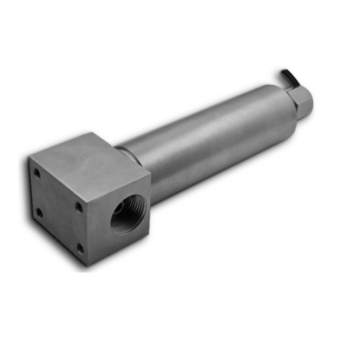
Pyxis ST-540SS-HR User manual

Table of Contents
1 Introducon 2
2 Specicaons 2
3 Unpacking Instrument 3
3.1 Standard Accessories . . . . . . . . . . . . . . . . . . . . . . . . . . . . . . . . . . . . . 3
3.2 Oponal Accessories . . . . . . . . . . . . . . . . . . . . . . . . . . . . . . . . . . . . . 3
4 Installaon 3
4.1 Wiring............................................. 4
4.2 Connecng via Bluetooth . . . . . . . . . . . . . . . . . . . . . . . . . . . . . . . . . . . 5
4.3 Connecng via USB . . . . . . . . . . . . . . . . . . . . . . . . . . . . . . . . . . . . . . 5
5 Setup and Calibraon with uPyxis® Mobile App 5
5.1 Download uPyxis® Mobile App . . . . . . . . . . . . . . . . . . . . . . . . . . . . . . . . 6
5.2 Connecng to uPyxis® Mobile App . . . . . . . . . . . . . . . . . . . . . . . . . . . . . . 6
5.3 Calibraon Screen and Reading . . . . . . . . . . . . . . . . . . . . . . . . . . . . . . . . 7
5.4 Diagnosis Screen . . . . . . . . . . . . . . . . . . . . . . . . . . . . . . . . . . . . . . . 7
5.5 Device Info Screen . . . . . . . . . . . . . . . . . . . . . . . . . . . . . . . . . . . . . . . 8
6 Setup and Calibraon with uPyxis® Desktop App 8
6.1 Install uPyxis® Desktop App . . . . . . . . . . . . . . . . . . . . . . . . . . . . . . . . . . 9
6.2 Connecng to uPyxis® Desktop App . . . . . . . . . . . . . . . . . . . . . . . . . . . . . 9
6.3 Informaon Screen . . . . . . . . . . . . . . . . . . . . . . . . . . . . . . . . . . . . . . 10
6.4 Calibraon Screen . . . . . . . . . . . . . . . . . . . . . . . . . . . . . . . . . . . . . . . 10
6.5 Diagnosis Screen . . . . . . . . . . . . . . . . . . . . . . . . . . . . . . . . . . . . . . . 12
7 Communicaon using Modbus RTU 12
8 Sensor Maintenance and Precauon 12
8.1 Methods to Cleaning ST Series Probe . . . . . . . . . . . . . . . . . . . . . . . . . . . . . 13
8.2 Storage ............................................ 13
9 Troubleshoong 14
10 Contact Us 14

Warranty Informaon
Condenality
The informaon contained in this manual may be condenal and proprietary and is the property of Pyxis
Lab, Inc. Informaon disclosed herein shall not be used to manufacture, construct, or otherwise reproduce
the goods described. Informaon disclosed herein shall not be disclosed to others or made public in any
manner without the express wrien consent of Pyxis Lab, Inc.
Standard Limited Warranty
Pyxis Lab warrants its products for defects in materials and workmanship. Pyxis Lab will, at its opon, repair
or replace instrument components that prove to be defecve with new or remanufactured components
(i.e., equivalent to new). The warranty set forth is exclusive and no other warranty, whether wrien or oral,
is expressed or implied.
Warranty Term
The Pyxis warranty term is thirteen (13) months ex-works. In no event shall the standard limited warranty
coverage extend beyond thirteen (13) months from original shipment date.
Warranty Service
Damaged or dysfunconal instruments may be returned to Pyxis for repair or replacement. In some in-
stances, replacement instruments may be available for short duraon loan or lease.
Pyxis warrants that any labor services provided shall conform to the reasonable standards of technical com-
petency and performance eecve at the me of delivery. All service intervenons are to be reviewed and
authorized as correct and complete at the compleon of the service by a customer representave, or des-
ignate. Pyxis warrants these services for 30 days aer the authorizaon and will correct any qualifying
deciency in labor provided that the labor service deciency is exactly related to the originang event. No
other remedy, other than the provision of labor services, may be applicable.
Repair components (parts and materials), but not consumables, provided during a repair, or purchased
individually, are warranted for 90 days ex-works for materials and workmanship. In no event will the in-
corporaon of a warranted repair component into an instrument extend the whole instrument’s warranty
beyond its original term.
Warranty Shipping
A Repair Authorizaon (RA) Number must be obtained from Pyxis Technical Support before any product can
be returned to the factory. Pyxis will pay freight charges to ship replacement or repaired products to the
customer. The customer shall pay freight charges for returning products to Pyxis. Any product returned to
the factory without an RA number will be returned to the customer. To receive an RMA you can generate a
request on our website at hps://pyxis-lab.com/request-tech-support/.
Pyxis Technical Support
Contact Pyxis Technical Support at +1 (866) 203-8397, [email protected], or by lling out a request for
support at hps://pyxis-lab.com/request-tech-support/.
1 Introducon
The Pyxis ST-540 Series probe measures the concentraon of naphthenic disulfonic acid (NDSA) in boiler
water and experimental applicaons. The ST-540 Series probe excites the sample water with a deep UV
light and measures a narrow band near UV uorescent emission. It can be connected to any controller that
accepts an isolated or non-isolated 4-20mA input. The ST-540 Series probe is a smart device, in addion
to measuring uorescence, the ST-540 Series probe has extra photo-electric components that monitor the
color and turbidity of the sample water. This extra feature allows automac color and turbidity compen-
saon to eliminate interference common in real-world samples. This can automacally compensate for
turbidity up to 150 NTU and color created by up to 10 ppm iron or equivalent to 10 ppm humic acid.
The ST-540 Series probe is easy to calibrate using the uPyxis® Mobile or Desktop App. The uPyxis® App
also provides diagnosc informaon about the ST-540 Series probe such as: probe fouling, color or turbid-
ity over range, failure modes, etc. This diagnosc informaon can also be available via Modbus RTU. The
ST-540 Series probe can be easily removed from the system for cleaning and calibraon without the need
for any tools.
2 Specicaons
Item Specicaon*
P/N 50667
Range 0-100 ppb
Resoluon 1 ppb
Calibraon Two-point calibraon against standard soluon
Outputs 4-20mA Analog Output, RS-485 Digital Output with Modbus protocol
Installaon 3/4” female NPT threaded ports on the probe itself
Cable Length 5 with IP67 connectors
Power Supply 22-26 VDC, 1 W
Dimension Length: 8.5 inch (220 mm), Head Cross-Secon: 2.25 x 1.75 inch (57.2 x 44.5
mm), Body Diameter: 1.66 inch (42.2 mm)
Weight 2.5 lbs (1130 g)
Material 304 Stainless Steel
Operaonal
Temperature
32-104 °F (0-40 °C)
Storage
Temperature
-4-140 °F (-20-60 °C)
Pressure Up to 290 psi (2.0 MPa) at 149 °F (65 °C)
Enclosure Rang IP67
Regulaon CE
*With Pyxis’s connuous improvement policy, these specicaons are subject to change without noce.

3 Unpacking Instrument
Remove the instrument and accessories from the shipping container and inspect each item for any damage
that may have occurred during shipping. Verify that all accessory items are included. If any item is missing
3.1 Standard Accessories
• 7-Pin Female Adapter/Flying Leads Cable (2 ) P/N: MA-1100
• User Manual available online at www.pyxis-lab.com/support.html
3.2 Oponal Accessories
Figure 1.
4 Installaon
The ST-540 Series probe has two 3/4” female NPT ports. It is recommended that two 3/4” NPT to 1/4”
tubing adapters are used to connect the probe to the sampling system. Sample water entering the probe
must be cooled down to below 104 °F (40 °C). The probe can be held by a 1.75-inch pipe clamp or mounted
to a panel with four 1/4-28 bolts. See Figure 2 for ST-540 Series dimensions.

Figure 2. Dimension of the ST-540 Series (inch)
4.1 Wiring
If the power ground terminal and the negave 4-20mA terminal in the controller are internally connected
(non-isolated 4-20mA input), it is unnecessary to connect the 4-20mA negave wire (green) to the 4-20mA
negave terminal in the controller. If a separate DC power supply other than that from the controller is
used, make sure that the output from the power supply is rated for 22-26 VDC @ 65mA.
*NOTE*The negave 24V power terminal (power ground) and the negave 4-20mA ter-
minal on the ST-540 Series probe are internally connected.
Follow the wiring table below to connect the ST-540 Series probe to a controller:
Wire Color Designaon
Red 24V +
Black 24V Power ground
White 4-20mA +
Green*4-20mA -
Blue RS-485 A
Yellow RS-485 B
Clear Shield, earth ground
*Internally connected to the power
ground

4.2 Connecng via Bluetooth
A Bluetooth adapter (P/N: MA-WB) can be used to connect an ST-540 Series probe to a smart phone with
the uPyxis® Mobile App or a computer with the uPyxis® Desktop App.
Figure 3. Bluetooth connecon to ST-540 Series probe
4.3 Connecng via USB
A USB-RS485 adapter (P/N: MA-485) can be used to connect an ST-540 Series probe to a computer with the
uPyxis® Desktop App.
*NOTE*Using non-Pyxis USB-RS485 adapters may result in permanent damage of the ST-
540 Series probe communicaon hardware.
Figure 4. USB connecon to ST-540 Series probe
5 Setup and Calibraon with uPyxis® Mobile App
The ST-540 Series probe can be calibrated in a two-point (zero + slope) procedure using a deionized water
sample and a standard containing 20 to 100 ppb NDSA. The calibraon soluon could be the sample water
itself. The concentraon of NDSA in the sample water can be determined by using a Pyxis SP-395N (P/N:
50226) or similar oine uorometer or calculated from the concentraon of any measurable species in the
sample water such as polymer, phosphate, or molybdate.
Direct sunlight or indoor light on the ST-540 Series probe should be avoided although it is not necessary
to completely shield the ST-540 Series probe from the ambient light during both the zero point and slope
calibraons.

5.1 Download uPyxis® Mobile App
Download uPyxis® Mobile App from Apple App Store or Google Play.
Figure 5.
5.2 Connecng to uPyxis® Mobile App
Turn on Bluetooth on your mobile phone (Do not pair the phone Bluetooth to the ST-540 Series probe).
Open uPyxis® Mobile App. Once the app is open the app will start to search for the sensor. Once the
uPyxis® Mobile App connects to the sensor, press the ST-540 Series probe.
Figure 6.

5.3 Calibraon Screen and Reading
When connected, the uPyxis® Mobile App will default to the Calibraon screen. From the Calibraon
screen, you can perform calibraons by pressing on Zero Calibraon,Slope Calibraon, and 4-20mA Span.
Follow the screen instrucons for each calibraon step.
Figure 7.
5.4 Diagnosis Screen
From the Diagnosis screen, you can check the diagnosis condion as well as Export & Upload. This feature
To preform a probe cleaniness check, rst select the Diagnosis Condion which denes the uid type that
the ST-540 Series probe in currently measuring, then press Cleanliness Check. If the probe is clean, a green
Clean message will be shown. If the probe is parally fouled, a yellow Becoming Dirty message will
be shown. If the probe is severely fouled, a red Dirty message will be shown. In this case, follow the
procedure in the Methods to Cleaning ST Series Probe secon of this manual.

Figure 8.
5.5 Device Info Screen
From the Device Info screen. You can name the Device or Product.
Figure 9.
6 Setup and Calibraon with uPyxis® Desktop App
The ST-540 Series probe can be calibrated in a two-point (zero + slope) procedure using a deionized water
sample and a standard containing 20 to 100 ppb NDSA. The calibraon soluon could be the sample water
itself. The concentraon of NDSA in the sample water can be determined by using a Pyxis SP-395N (P/N:

50226) or similar oine uorometer or calculated from the concentraon of any measurable species in the
sample water such as polymer, phosphate, or molybdate.
Direct sunlight or indoor light on the ST-540 Series probe should be avoided although it is not necessary
to completely shield the ST-540 Series probe from the ambient light during both the zero point and slope
calibraons.
6.1 Install uPyxis® Desktop App
Download the latest version of uPyxis® Desktop soware package from: hp://www.pyxis-lab.com/sup-
port.html this setup package will download and install the Microso.Net Framework 4.5 (if not previously
installed on the PC), the USB driver for the USB-Bluetooth adapter (MA-NEB), the USB-RS485 adapter (MA-
485), and the main uPyxis® Desktop applicaon. Double click the uPyxis.Setup.exe le to install.
Figure 10.
Click Install to start the installaon process. Follow the screen instrucons to complete the USB driver and
uPyxis® installaon.
6.2 Connecng to uPyxis® Desktop App
When the uPyxis® Desktop App opens, to nd your device, click on Device, then Connect via USB-RS485.
Figure 11.

6.3 Informaon Screen
Once connected to the device, a picture of the device will appear on the top le corner of the window and
the uPyxis® Desktop App will default to the Informaon screen. On the Informaon screen you can set the
informaon descripon for Device Name and Product Name, then click Set to save.
Figure 12.
6.4 Calibraon Screen
To calibrate the device, click on Calibraon. On the Calibraon screen there are three calibraon tabs, Zero
Calibraon,Slope Calibraon, and 4-20mA Span. The screen also displays the reading of the device. The
reading refresh rate is every 4 seconds.
Figure 13.

6.4.1 Zero Calibraon
To perform Zero Calibraon, click on Zero Calibraon. Then follow the instrucon on how to calibrate, then
click Ok.
6.4.2 Slope Calibraon
To perform Slope Calibraon, click on Slope Calibraon. Then follow the instrucon on how to calibrate,
then click Slope Calibraon.
Figure 14.
6.4.3 4-20mA Span
To perform 4-20mA Span, click on 4-20mA Span. Then follow the instrucons provided to alter the 4-20mA
output span of the sensor, then click Set 20mA Span. Each sensor format will have a maximum 20 mA range
allowed. 4-20mA Span setup must be maintained within the limit of its respecve sensor.
Figure 15.

6.5 Diagnosis Screen
Aer the device has been calibrated and installaon has been completed, to check diagnosis, click on Diag-
nosis. When in the Diagnosis screen you can view the Diagnosis Condion of the device. This feature may
To preform a probe cleaniness check, rst select the Diagnosis Condion which denes the uid type that
the ST-540 Series probe in currently measuring, then click Cleanliness Check. If the probe is clean, a green
Clean message will be shown. If the probe is parally fouled, a yellow Becoming Dirty message will
be shown. If the probe is severely fouled, a red Dirty message will be shown. In this case, follow the
procedure in the Methods to Cleaning ST Series Probe secon of this manual.
Figure 16.
7 Communicaon using Modbus RTU
The ST-540 Series probe is congured as a Modbus slave device. In addion to the ppb NDSA value, many
operaonal parameters, including warning and error messages, are available via a Modbus RTU connecon.
8 Sensor Maintenance and Precauon
The ST-540 Series probe is designed to provide reliable and connuous NDSA readings even when installed
in moderately contaminated industrial cooling waters. Although the opcs are compensated for the eects
of moderate fouling, heavy fouling will prevent the light from reaching the sensor, resulng in low readings
and the potenal for product overfeed if the ST-540 Series probe is used as part of an automated control
system. When used to control product dosing, it is suggested that the automaon system be congured
to provide backup to limit potenal product overfeed, for example by liming pump size or duraon, or by
alarming if the pumping rate exceeds a desired maximum limit.
The ST-540 Series probe is designed to be easily removed, inspected, and cleaned if required. It is suggested
that the ST-540 Series probe be checked for fouling and cleaned/calibrated on a monthly basis. Heavily con-
taminated waters may require more frequent cleanings. Cleaner water sources with less contaminaon may
not require cleaning for several months.

The need to clean the ST-540 Series probe can be determined by the Cleanliness Check using either the
uPyxis® Mobile App (see the Mobile Diagnosis Screen secon) or the uPyxis® Desktop App (see the Desk-
top Diagnosis Screen secon).
8.1 Methods to Cleaning ST Series Probe
Any equipment in contact with industrial cooling systems is subject to many potenal foulants and con-
taminants. Our inline probe cleaning soluons below have been shown to remove most common foulants
and contaminants. A small, so bristle brush, Q-Tips coon swab, or so cloth may be used to safely clean
the probe housing and the quartz opcal sensor channel. These components and more come with a Pyxis
Lab Inline Probe Cleaning Soluon Kit (P/N: SER-01) which can be purchased at our online Estore/Catalog
hps://pyxis-lab.com/product/st-series-probe-cleaning-kit/
Figure 17. Inline Probe Cleaning Soluon Kit
To clean the ST series probe, soak the lower half of the probe in 100 mL inline probe cleaning soluon for
30 minutes. Rinse the ST series probe with dislled water and then check for the ashing blue light inside
the ST series probe quartz tube. If the surface is not enrely clean, connue to soak the ST series probe for
an addional 30 minutes. Use the small, so bristle brush and Q-Tips coon swabs as necessary to remove
any remaining contaminants in the ST series probe quartz tube.
8.2 Storage
Avoid long term storage at temperature over 140 °F. In an outdoor installaon, properly shield the ST-540
Series probe from direct sunlight and precipitaon.

9 Troubleshoong
If the ST-540 Series probe output signal is not stable and uctuates signicantly, make an addional ground
connecon – connect the clear (shield, earth ground) wire to a conductor that contacts the sample water
electrically such as a metal pipe adjacent to the ST-540 Series tee.
Carry out roune calibraon vericaon against a qualied NDSA standard. Aer properly cleaning the ST-
540 Series sensor, carry out the zero point calibraon with dislled water and slope calibraon using the
qualied NDSA standard.
10 Contact Us
Pyxis Lab, Inc
1729 Majesc Dr. Suite 5
Lafayee, CO 80026 USA
www.pyxis-lab.com
Phone: +1 (866) 203-8397
Email: [email protected]
This manual suits for next models
2
Table of contents
Other Pyxis Measuring Instrument manuals

Pyxis
Pyxis IK-765SS-O3 User manual

Pyxis
Pyxis SP-395T TTA User manual

Pyxis
Pyxis SP-200 OXIPOCKET User manual

Pyxis
Pyxis SP-380P User manual

Pyxis
Pyxis PermaCheck EZ-101 User manual

Pyxis
Pyxis SP-900 User manual

Pyxis
Pyxis SP-910 User manual

Pyxis
Pyxis SP-350 User manual

Pyxis
Pyxis SP-395 User manual

Pyxis
Pyxis HM-500 Series User manual

Pyxis
Pyxis SP-350RO User manual

Pyxis
Pyxis PRISM RT-100 User manual

Pyxis
Pyxis ST-601 User manual

Pyxis
Pyxis ST-774 User manual

Pyxis
Pyxis PRISM RT-100 User manual

Pyxis
Pyxis SP-710 User manual

Pyxis
Pyxis SP-210 User manual

Pyxis
Pyxis ST-500 User manual

Pyxis
Pyxis SP-395T User manual

Pyxis
Pyxis ST-600 Quick start guide