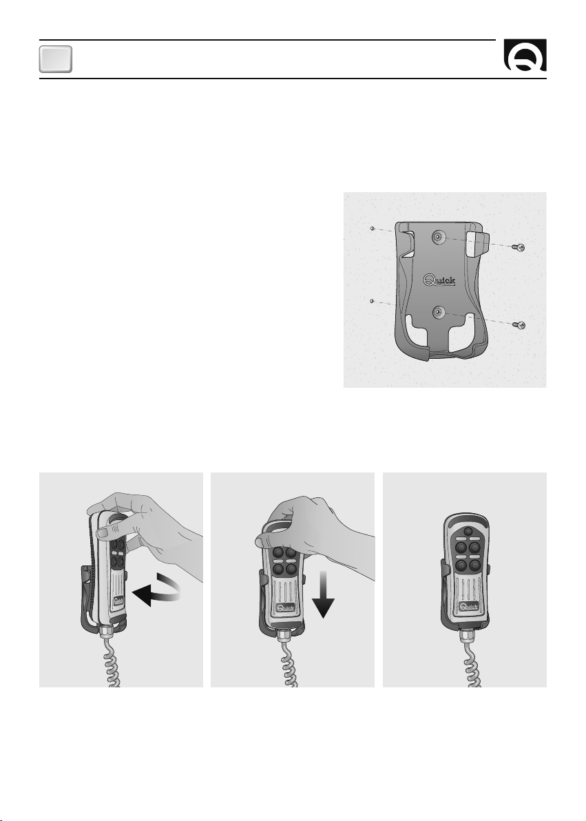
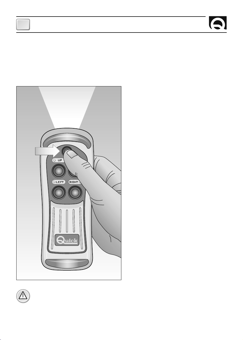
Quick HRC 1002 User manual

REV 004A
High
Quality
Nautical
Equipment
Manuale d'uso PULSANTIERA MULTIUSO HRC
User's Manual HRC MULTIPURPOSE CONTROL PANEL
Manuel de l'utilisateur BOITIER DE COMMANDE MULTI-USAGE HRC
Benutzerhandbuch MEHRZWECK-FERNBEDIENUNG HRC
Manual del usuario TABLERO DE PULSADORES MULTIUSO HRC
MULTIPURPOSE CONTROL PANEL
HRC 1002
HRC 1004
HRC 1006
HRC 1008
HRC 1002 L
HRC 1004 L
HRC 1006 L
HRC 1008 L
IT
GB
FR
DE
ES


3
HRC - REV004A
Pag. 4 Caratteristiche e Installazione - installazione della presa
Pag. 5 Installazione - installazione della presa
Pag. 6 Installazione - Supporto
Pag. 7 Installazione - Supporto
Pag. 8 Installazione / Funzionamento - personalizzazione della pulsantiera
- connessione alla presa
Pag. 9 Installazione - schemi di collegamento
Pag. 10 Funzionamento - accensione e spegnimento della torcia
Pag. 11 Manutenzione / Caratteristiche tecniche
INDICE
Pg. 12 Characteristics and installation - installing the socket
Pg. 13 Installation - installing the socket
Pg. 14 Installation - Support
Pg. 15 Installation - Support
Pg. 16 Installation / Operating - personalizing the control panel
- connecting to the socket
Pg. 17 Installation - connection diagrams
Pg. 18 Operating - switching the torch on and off
Pg. 19 Maintenance / Technical data
P. 20 Caractéristiques et installation - installation de la prise
P. 21 Installation - installation de la prise
P. 22 Installation - Support
P. 23 Installation - Support
P. 24 Installation / Fonctionnement - personnalisation du boitier de commande
- connexion du boîtier de commande à la prise
P. 25 Installation - schémas de branchement
P. 26 Fonctionnement - allumage et extinction de la torche
P. 27 Entretien / Caractéristiques techniques
SOMMAIRE
S. 28 Eigenschaften und Installation - Installation der Steckdose
S. 29 Installation - Installation der Steckdose
S. 30 Installation - Halterung
S. 31 Installation - Halterung
S. 32 Installation / Betrieb - Personaliche gestaltung der Fernbedienung
- Anschluss der Fernbedienung an die Steckdose
S. 33 Installation - Anschlusstafeln
S. 34 Betrieb - Anschluss und Ausschalten der Lampe
S. 35 Wartung / Technische daten
INHALTSANGABE
Pág. 36 Características e Instalación - instalación de la toma
Pág. 37 Instalación - instalación de la toma
Pág. 38 Instalación - Soporte
Pág. 39 Instalación - Soporte
Pág. 40 Instalación / Funcionamiento - personalización del tablero de pulsadores
- conexión del tablero de pulsadores en la toma
Pág. 41 Instalación - esquema de conexión
Pág. 42 Funcionamiento - prender y apagar la antorcha
Pág. 43 Mantenimiento / Especificaciones técnicas
INDICE
INDEX
IT
GB
FR
DE
ES

4
CARATTERISTICHE E INSTALLAZIONE
IT
HRC - REV004A
PULSANTIERA MULTIUSO
La pulsantiera multiuso Quick
®
è uno strumento progettato per azionare a distanza vari sistemi mobili a
bordo dell'imbarcazione come gruette, passerelle, scalette-bagno, salpa ancora.
INSTALLAZIONE
PRIMA DI UTILIZZARE LO STRUMENTO, LEGGERE ATTENTAMENTE IL PRESENTE MANUALE
D'USO. IN CASO DI DUBBI CONTATTARE IL RIVENDITORE O IL SERVIZIO CLIENTI QUICK
®.
In caso di discordanze o eventuali errori tra il testo tradotto e quello originario in italiano, fare riferi-
mento al testo italiano o inglese.
Questo dispositivo è stato progettato e realizzato per essere utilizzato su imbarcazioni da diporto.
Non è consentito un utilizzo differente senza autorizzazione scritta da parte della società Quick
®
.
La pulsantiera è stata progettata per gli scopi descritti in questo manuale d'uso. La società Quick
®
non si
assume alcuna responsabilità per danni diretti o indiretti causati da un uso improprio dell'apparecchio, da
un'errata installazione o da possibili errori presenti in questo manuale.
ATTENZIONE: l'utilizzatore elettrico, comandato dalla pulsantiera, deve essere dotato di sistemi di
sicurezza tali da impedire danni a persone, cose o all'ambiente che possano generarsi da un difetto
di funzionamento della pulsantiera.
L'APERTURA DELLO STRUMENTO DA PARTE DI PERSONALE NON AUTORIZZATO FA
DECADERE LA GARANZIA.
LA CONFEZIONE CONTIENE: pulsantiera - supporto - presa - guarnizione e coperchio presa - viti - dima
di foratura - adesivi personalizzati (solo in alcuni modelli) - il presente manuale d'uso.
INSTALLAZIONE DELLA PRESA
Di seguito sarà descritta una procedura di installazione tipica. Non è possibile descrivere una procedura
che sia applicabile a tutte le situazioni. Adattare questa procedura per soddisfare i propri requisiti.
Individuare la posizione più adatta dove praticare la sede per alloggiare la presa seguendo questi criteri:
• La presa deve essere posizionata in modo che sia facilmente raggiungibile dall'operatore.
• Scegliere una posizione che sia pulita, liscia e piana.
• Deve essere presente un accesso posteriore per l'installazione e la manutenzione.
• Deve esistere spazio sufficiente dietro alla posizione scelta per il libero passaggio del cavo della presa.
• La parte posteriore della presa deve essere protetta dal contatto con acqua o umidità.
• Porre particolare attenzione quando si effettuano i fori sui pannelli o su parti dell'imbarcazione.
Questi fori non devono indebolire o causare rotture alla struttura dell'imbarcazione.
F
F

5
INSTALLAZIONE
IT
HRC - REV004A
Dopo aver scelto dove posizionare la presa, procedere come riportato di seguito:
• Posizionare la dima di foratura (fornita in dotazione) sulla superficie dove sarà installata la presa.
• Marcare il centro di ogni foro.
• Realizzare il foro per il passaggio del cavo della presa con una fresa.
• Rimuovere la dima ed eventuali bave presenti sul foro.
• Applicare la guarnizione alla base della presa.
• Inserire il cavo nel foro praticato.
• Fissare la presa avvitando le 4 viti in dotazione.
• Prima di procedere con i collegamenti elettrici accertarsi che l'alimentazione non sia presente.
• Per il collegamento elettrico dei cavi, riferirsi alla colorazione dei cavi in fig. 2.
• Inserire un fusibile rapido da 200mA sulla linea di alimentazione della torcia (cavi A e B, se presenti).
• Alimentare la pulsantiera solo dopo aver effettuato e verificato l'esattezza di tutti i collegamenti
elettrici.
UP DOWN
LEFT RIGHT

6
IT
HRC - REV004A
INSTALLAZIONE DEL SUPPORTO
Di seguito sarà descritta una procedura di installazione tipica. Non è possibile descrivere una procedura
che sia applicabile a tutte le situazioni.
Adattare questa procedura per soddisfare i propri requisiti. Individuare la posizione più adatta dove
posizionare il supporto seguendo questi criteri:
• Il supporto deve essere posizionato in modo che sia
facilmente raggiungibile dall'operatore.
• Scegliere una posizione che sia pulita, liscia e piana.
• Accertarsi che la parte posteriore del pannello in cui
saranno avvitate le viti del supporto sia libera dal
passaggio di cavi, tubi, ecc.
• Porre particolare attenzione quando si avvitano le viti sui
pannelli o su parti dell'imbarcazione.
Le viti non devono indebolire o causare rotture alla
struttura dell'imbarcazione.
• Appoggiare il supporto sulla superficie scelta.
• Fissare il supporto avvitando le 2 viti in dotazione.
INSERIMENTO DELLA PULSANTIERA NEL SUPPORTO
Per inserire la pulsantiera nel supporto seguire le indicazioni presenti nella sequenza illustrata:
Inserire la pulsantiera leggermente ruotata all'interno del supporto, completare la rotazione finchè la
pulsantiera non sarà parallela al supporto.
Spingere la pulsantiera verso il basso fino ad inserirla completamente nel supporto.
INSTALLAZIONE

7
IT
HRC - REV004A
ESTRAZIONE DELLA PULSANTIERA DAL SUPPORTO
Per estrarre la pulsantiera dal supporto seguire le indicazioni presenti nella sequenza illustrata:
Sfilare la pulsantiera dal suo supporto alzandola di qualche centimetro, ruotarla o in un senso o nell'altro;
estrarre la pulsantiera dal supporto alzandola.
INSTALLAZIONE

8
IT
HRC - REV004A
ATTENZIONE: l'applicazione dell'adesivo non è consigliata se la temperatura della superficie della
pulsantiera è inferiore a 10°C.
CONNESSIONE DELLA PULSANTIERA ALLA PRESA
Connessione dello strumento
Dopo avere installato la presa come descritto in precedenza, procedere come riportato di seguito:
• Ruotare la ghiera del coperchio di protezione in senso antiorario ed estrarlo.
• Inserire la spina dello strumento nell'apposita presa facendo attenzione al verso d'inserzione.
• Ruotare la ghiera della spina in senso orario fino a serrarla completamente.
Disconnessione dello strumento
• Ruotare la ghiera della spina in senso antiorario fino a svitarla completamente ed estrarla.
• Coprire la presa con l'apposito coperchio, ruotando la ghiera in senso orario.
ATTENZIONE: assicurarsi di coprire la presa con l'apposito coperchio, quando lo strumento è
disconnesso.
PERSONALIZZAZIONE DELLA PULSANTIERA
In alcuni modelli di HRC, la simbologia associata a ciascuno dei tasti può essere variata grazie agli adesivi
in dotazione. Di seguito sarà descritta la procedura per la personalizzazione della pulsantiera:
• Pulire le apposite superfici (fig. 1) con un panno morbido inumidito di acqua.
• Scegliere l'adesivo da posizionare sulla superficie pulita in precedenza.
• Centrare l'adesivo sulla superficie senza esercitare pressione e premere l'adesivo sulla superficie per 5
secondi.
FIG.1
5"
INSTALLAZIONE E FUNZIONAMENTO

9
IT
HRC - REV004A
1
2
A
B
1
2
3
4
A
B
1
2
3
4
5
6
7
8
A
B
1
2
3
2
4
2
4
6
8
2
4
6
1
3
1
3
5
7
1
3
5
4
5
6
A
B
21
1
2
3
4
5
6
1
2
1
2
3
4
1
2
3
4
5
6
7
8
22
4
2
4
6
8
2
4
6
11
3
1
3
5
7
1
3
5
HRC 1002 HRC 1004 HRC 1006 HRC 1008
MARRONE COMUNE
BLU
NERO
BIANCO
VERDE
ROSSO
GRIGIO
ARANCIO
GIALLO
MARRONE COMUNE
BLU
NERO
BIANCO
VERDE
ROSSO
GRIGIO
MARRONE COMUNE
BLU
NERO
BIANCO
VERDE
MARRONE COMUNE
BLU
NERO
MARRONE COMUNE
BLU
NERO
BIANCO
VERDE
ROSSO
GRIGIO
ARANCIO
GIALLO
VIOLA
TURCHESE
VIOLA
TURCHESE
MARRONE COMUNE
BLU
NERO
BIANCO
VERDE
ROSSO
GRIGIO
VIOLA
TURCHESE
MARRONE COMUNE
BLU
NERO
BIANCO
VERDE
VIOLA
TURCHESE
MARRONE COMUNE
BLU
NERO
HRC 1002 L HRC 1004 L HRC 1006 L HRC 1008 L
FIG.2
e alimentazione torcia (senza polarità).
AB
INSTALLAZIONE

10
IT
HRC - REV004A
ATTENZIONE: nei modelli HRC 1002, HRC 1004, HRC 1006, HRC 1008 è presente il tasto con il
simbolo della luce anche se non sono dotati della torcia.
ACCENSIONE E SPEGNIMENTO DELLA TORCIA
HRC 1002 L - HRC 1004 L - HRC 1006 L - HRC 1008 L
L'accensione e lo spegnimento della torcia avviene premendo e rilasciando il pulsante che si trova in alto
con il simbolo della luce, vedere fig. 3.
All'accensione dello strumento la torcia è sempre spenta, anche se in precedenza lo strumento è stato
disconnesso dall'alimentazione con la torcia accesa.
FIG.3
FUNZIONAMENTO

11
IT
HRC - REV004A
MODELLO
HRC 1002 HRC1004 HRC 1006 HRC 1008
HRC 1002 L HRC 1004 L HRC 1006 L HRC 1008 L
CARATTERISTICHE ELETTRICHE
Portata in corrente dei contatti
(1)
Tensione alimentazione torcia
(2)
Assorbimento torcia
(2)
4A
6 ÷ 30 Vdc
100mA Max
4.2 m
EN 55022/B
GENERALI
Massima estensione cavo
Classe EMC
62.2 x 185 x 49.4 mm
CONTENITORE
Dimensioni (LxAxP)
-15 ÷ +70 °C
IP 67
CARATTERISTICHE AMBIENTALI
Temperatura operativa
Grado di protezione
(3)
(1)
Su carico resistivo a 30 Vdc.
(2)
Solo nei modelli HRC 1002 L - HRC 1004 L - HRC 1006 L - HRC 1008 L.
(3)
Con la spina correttamente inserita nella presa. Esclusa la zona della presa dove è saldato il cavo di uscita (IP 00).
CARATTERISTICHE TECNICHE
MANUTENZIONE
Lo strumento non richiede una particolare manutenzione. Per assicurare il funzionamento ottimale
dell'apparecchio verificare, una volta all'anno, i cavi e le connessioni elettriche. Pulire lo strumento con un
panno morbido, inumidito di acqua. Non utilizzare prodotti chimici o abrasivi per pulire lo strumento.
QUICK
®
SI RISERVA IL DIRITTO DI APPORTARE MODIFICHE ALLE CARATTERISTICHE TECNICHE DELL'APPARECCHIO E AL CONTENUTO DI QUESTO MANUALE SENZA ALCUN PREAVVISO.
MANUTENZIONE - CARATTERISTICHE TECNICHE

12
GB
HRC - REV004A
MULTIPURPOSE CONTROL PANEL
The Quick
®
multipurpose control panel is an instrument designed for the remote control of various moving
systems on board a boat, including mini-crane, gangplank, swimming ladder, anchor hoist.
INSTALLATION
BEFORE USING THE INSTRUMENT PLEASE STUDY THIS USER MANUAL. IN CASE OF ANY
DOUBT PLEASE CONTACT THE RETAILER OR QUICK
®
CUSTOMER SERVICE.
In case of discordance or errors in translation between the translated version and the original text in
the Italian language, reference will be made to the Italian or English text.
This device was designed and constructed for use on recreational crafts.
Other forms of use are not permitted without written authorization from the company Quick
®
.
The control was designed for the purposes described in this user manual. The company Quick
®
does
not accept any responsibility for direct or indirect damage caused by the improper use of the device, by
incorrect installation, or for any errors in this user manual.
WARNING: the electrical appliance controlled by the control panel must be provided with safety
systems to prevent damage to persons, things, or the environment that might result from the
defective operation of the control panel.
THE OPENING OF THE INSTRUMENT BY UNAUTHORIZED PERSONNEL MAKES THE
WARRANTY VOID.
THE PACKAGE CONTAINS:
control panel - support - socket - socket seal and cover - screws - drilling
template - personalised adhesives (only in certain models) - the present manual of use.
FITTING THE SOCKET
A typical installation procedure is described below.
It is not possible to define a single procedure that is applicable in every situation.
Adapt the procedure described here to your own requirements.
Identify the most appropriate position for the socket seating on the basis of the following criteria:
• The socket must be positioned so that it can easily be reached by the operator.
• Choose a clean, smooth, flat location.
• Rear access is required for installation and maintenance.
• There must be sufficient space behind the chosen position for the passage of the socket cable.
• The back of the socket must not be exposed to contact with water or humidity.
• Take particular attention when drilling the panels or parts of the boat. The holes must not weaken or
cause the breakage of structural elements of the boat.
CHARACTERISTICS AND INSTALLATION
F
F

13
GB
HRC - REV004A
After choosing where to position the instrument, proceed as follows:
• Position the drilling template (provided) on the surface where the socket will be installed.
• Mark the centre of each hole.
• Create the hole for the passage of the socket cable with a milling cutter.
• Remove the template and any splinters around the hole.
• Fit the seal to the socket base.
• Put the cable through the hole created.
• Fix the socket in position with the 4 screws provided.
• Before making the electrical connections ensure that the electrical supply is not connected.
• For the connection of the electrical wires refer to the wire colouring as in fig. 1.
• Insert a fast-acting fuse of 200mA on the torch supply line (wires A and B, if present).
• Before switching on the power to the control, check that all the electrical connections are correct.
INSTALLATION
UP DOWN
LEFT RIGHT

14
GB
HRC - REV004A
INSTALLING THE SUPPORT
The standard installation procedure is described below. Unfortunately we cannot describe a procedure
applicable to all the situations.
Adapt this procedure to satisfy your own individual requirements.
Find the spot most suitable for the support based on the following criteria:
• The support must be positioned so that it can easily be
reached by the operator.
• Choose a clean, smooth, flat location.
• Check that the back of the panel into which the screws of
the support will be inserted is free from
passing cables, tubes, etc.
• Take particular attention when screwing into the panels or
parts of the boat.
The screws must not weaken or cause the breakage of
structural elements of the boat.
• Place the support onto the chosen surface.
• Fix the support with the 2 screws provided.
INSERTING THE CONTROL PANEL INTO THE SUPPORT
To insert the control panel into the support, follow the instructions in the illustrated sequence:
Insert the control panel slightly rotated into the support and continue the rotation until the control panel
is parallel with the support.
Push the control panel down until it is fully inserted into the support.
INSTALLATION

15
GB
HRC - REV004A
EXTRACTING THE CONTROL PANEL FROM THE SUPPORT
To extract the control panel from the support, follow the instructions in the illustrated sequence:
Slide the control panel from its support by raising it a few centimetres, rotate in either direction and then
extract it from the support by raising it.
INSTALLATION

16
GB
HRC - REV004A
WARNING: the application of adhesives is not recommended if the temperature of the
surface of the control panel is below 10°C.
CONNECTING THE CONTROL PANEL TO THE SOCKET
Connecting the instrument
After installing the socket as described above, proceed as follows:
• Rotate the ring-nut of the protective cover anticlockwise and remove it.
• Insert the instrument plug into the relevant socket, taking care that the position of insertion is
correct.
• Turn the plug locking ring-nut clockwise until fully closed.
Disconnecting the instrument
• Turn the plug locking ring-nut anticlockwise until fully open and remove.
• Cover the socket with the cover provided, turning the ring-nut clockwise.
WARNING: always ensure that the socket is closed with the cover provided when the instrument
is disconnected.
PERSONALIZING THE CONTROL PANEL
In some HRC models the symbols on the individual keys can be changed by applying the stickers provided.
The procedure for personalizing the control panel is as follows:
• Clean the relevant surfaces with a soft cloth dampened with water (fig. 1).
• Choose a sticker for application to the surface cleaned previously.
• Centre the sticker on the surface without applying pressure and then press it down on the
surface for 5 seconds.
FIG.1
5"
INSTALLATION - OPERATING

17
GB
HRC - REV004A
1
2
A
B
1
2
3
4
A
B
1
2
3
4
5
6
7
8
A
B
1
2
3
2
4
2
4
6
8
2
4
6
1
3
1
3
5
7
1
3
5
4
5
6
A
B
21
1
2
3
4
5
6
1
2
1
2
3
4
1
2
3
4
5
6
7
8
22
4
2
4
6
8
2
4
6
11
3
1
3
5
7
1
3
5
HRC 1002 HRC 1004 HRC 1006 HRC 1008
BROWN ROUND
BLUE
BLACK
WHITE
GREEN
RED
GREY
ORANGE
YELLOW
BROWN ROUND
BLUE
BLACK
WHITE
GREEN
RED
GREY
BROWN ROUND
BLUE
BLACK
WHITE
GREEN
BROWN ROUND
BLUE
BLACK
BROWN ROUND
BLUE
BLACK
WHITE
GREEN
RED
GREY
ORANGE
YELLOW
PURPLE
TURQUOISE
PURPLE
TURQUOISE
BROWN ROUND
BLUE
BLACK
WHITE
GREEN
RED
GREY
PURPLE
TURQUOISE
BROWN ROUND
BLUE
BLACK
WHITE
GREEN
PURPLE
TURQUOISE
BROWN ROUND
BLUE
BLACK
HRC 1002 L HRC 1004 L HRC 1006 L HRC 1008 L
FIG.2
INSTALLATION

18
GB
HRC - REV004A
WARNING: models HRC 1002, HRC 1004, HRC 1006, HRC 1008 have the button with the light sym-
bol even though they are not equipped with a torch.
SWITCHING THE TORCH ON AND OFF
HRC 1002 L - HRC 1004 L - HRC 1006 L - HRC 1008 L
The torch is switched on and off by pressing and releasing the button at the top with the light
symbol, see fig. 3. When the instrument is first switched on the torch is always off, even if previously
disconnected from the supply with the torch on.
FIG.3
OPERATING

19
GB
HRC - REV004A
MODEL
HRC 1002 HRC1004 HRC 1006 HRC 1008
HRC 1002 L HRC 1004 L HRC 1006 L HRC 1008 L
ELECTRICAL CHARACTERISTICS
Current capacity of contacts
(1)
Torch supply voltage
(2)
Torch power absorption
(2)
4A
6 ÷ 30 Vdc
100mA Max
4.2 m
EN 55022/B
GENERAL
Maximum cable extension
EMC class
62.2 x 185 x 49.4 mm
CASE
Dimensions (LxHxD)
-15 ÷ +70 °C
IP 67
AMBIENT CHARACTERISTICS
Operating temperature
Protection rating
(3)
(1)
On resistive load at 30 Vdc.
(2)
Only on models HRC 1002 L - HRC 1004 L - HRC 1006 L - HRC 1008 L.
(3)
With the plug correctly inserted into the socket. Excluding the area of the socket where the exit cable is fixed (IP 00).
TECHNICAL DATA
QUICK
®
RESERVES THE RIGHT TO MODIFY THE TECHNICAL CHARACTERISTICS OF THE EQUIPMENT AND THE CONTENTS OF THIS MANUAL WITHOUT PRIOR NOTICE.
MAINTENANCE
The control panel does not require any particular maintenance. To assure top performance, check the
cables and electrical connections once a year.
Clean the instrument with a soft rag dampened in water. Do not use chemicals or harsh products to clean
the chain counter.
MAINTENANCE - TECHNICAL DATA

20
FR
HRC - REV004A
BOITIER DE COMMANDE MULTI-USAGE
Le boîtier de commande Quick
®
est un instrument conçu pour actionner à distance différents systèmes
mobiles à bord du bateau comme des grues, des passerelles, des échelles de bain, des guindeaux.
INSTALLATION
AVANT D'UTILISER L'INSTRUMENT, LIRE ATTENTIVEMENT CE MODE D'EMPLOI.
EN CAS DE DOUTES, CONTACTER LE REVENDEUR OU LE SERVICE CLIENTELE QUICK
®
.
En cas de discordances ou d’erreurs éventuelles entre la traduction et le texte original en italien, se
référer au texte italien ou anglais.
Ce dispositif a été conçu et réalisé pour être utilisé sur des bateaux de plaisance.
Tout autre emploi est interdit sans autorisation écrite de la société Quick
®
.
Le boîtier de commande a été conçu pour les utilisations décrites dans ce mode d'emploi. La firme Quick
®
n'assume aucune responsabilité en cas de dommages directs ou indirects causés par une utilisation
impropre de l'appareil, par une mauvaise installation ou par des erreurs éventuelles dans ce manuel.
ATTENTION:
l'appareil électrique, commandé par le boîtier de commande, doit être équipé de systè-
mes de sécurité visant à empêcher les dommages aux personnes, aux biens ou à l'environnement,
qui pourraient être dus à un défaut de fonctionnement du boîtier de commande.
L'OUVERTURE DE L'INSTRUMENT PAR DU PERSONNEL NON AUTORISE REND
AUTOMATIQUEMENT LA GARANTIE NON VALIDE.
L'EMBALLAGE CONTIENT: le boîtier de commande - le support - la prise - la garniture et le couvercle
de la prise - les vis - le gabarit de perçage - adhésifs personnalisés (seulement sur certains modèles) - le
mode d'emploi.
INSTALLATION DE LA PRISE
La procédure d'installation typique est décrite ci-après.
Il n'est pas possible de fournir une procédure qui soit applicable à toutes les situations.
Adapter cette procédure pour répondre aux propres conditions requises.
Déterminer la position la plus adaptée où préparer l'emplacement de la prise en suivant ces critères:
• La prise doit être placée de façon à être facilement accessible par l'opérateur.
• Choisir une position propre, lisse et plate.
• Il faut un accès par l'arrière pour l'installation et l'entretien.
• Il faut un espace suffisant derrière la position choisie pour le libre passage du câble de la prise.
• La partie postérieure de la prise doit être protégée du contact avec l'eau ou l'humidité.
• Faire particulièrement attention quand on perce les trous sur les panneaux ou sur des pièces du bateau.
• Ces trous ne doivent pas affaiblir ou causer de ruptures à la structure du bateau.
CARACTÉRISTIQUES ET INSTALLATION
F
F
This manual suits for next models
3
Table of contents
Languages:
Other Quick Boating Equipment manuals

Quick
Quick DP1 312 User manual

Quick
Quick mc2X 25k Guide

Quick
Quick BTQ Series User manual

Quick
Quick DAVE DV 1712 X/Y User manual

Quick
Quick MC2X 56k Guide

Quick
Quick DV5 Dave Series Reference manual

Quick
Quick Prince DP1 Series User manual

Quick
Quick DP3 712 User manual

Quick
Quick ARIES User manual

Quick
Quick BTQ2512012 User manual

Quick
Quick AL3 ALEPH Series User manual

Quick
Quick DP3 712 User manual

Quick
Quick MC2 X13 DC Guide

Quick
Quick A 712 User manual

Quick
Quick BL2 FF Y Series Guide

Quick
Quick GP Series User manual

Quick
Quick RG5 Series User manual

Quick
Quick ARIES 700W User manual

Quick
Quick PRINCE DP2E Series User manual

Quick
Quick BT DC-AC Guide