BGA2015 OPERATION MANUAL
Page1
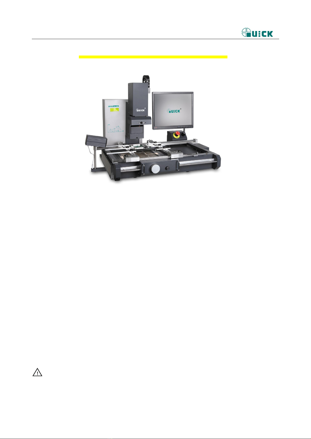
1. Summary
Thank you for using QUICK BGA EA-H00 Rework System. This system, which adopts
micro-processor control and infrared sensor technology to do soldering and de-soldering to
surface mount components safely and accurately, increases bottom heating power based on the
original one. It can also control the whole technical process and record all the information by
means of the IR Software, thus meeting the higher technical demands of modern electronic
industry. It becomes one of the most valued electronic equipments in this field. QUICK BGA
EA-H00 consists of two parts: QUICK IR EA-H00 Infrared Rework System and QUICK PL
EA-H00 Precision Placement System.
In order to control the soldering process optimally and get the nondestructive and
reproductive PCB temperature, IR EA-H00’s heating power is up to 2400W, suitable for all
applications, such as large or small PCB as well as lead-free process. The technology of re-flow
soldering controlled by closed-loop ensures the precise and smaller technical window, even heat
distribution and appropriate peak value of temperature for lead-free soldering.
IR EA-H00 Rework System adopts micro-processor control and infrared sensor technology.
It has the precision non-contact infrared temperature sensor for de-soldering parts and the
middle wavelength infrared heater. The soldering process is under the monitoring of
non-contact infrared sensor and optimum control of process can be achieved at any time. The
middle-wavelength infrared heater has a well-proportioned and safe heating and power and
flexibleness necessary for the system, so it can also deal with some PCBs with big thermal
capacity and other high temperature situation (lead-free soldering) easily. The adjustable
aperture under the infrared heater can protect the adjacent components (which are sensitive to
the temperature) on PCB from being heated. No need for nozzles.
IR EA-H00 works under the “open environment”, that is, it can calibrate and test
temperature in soldering process. When the melting of solder is found by visual inspection,
press down the calibrating button to record the melting temperature of solder. IR EA-H00 has
10 types of working modes and programmable temperature controlling can modify the
parameters of every working modes. IR system and setting of parameters are operated by
outside Keyboard as well as by IR soft.