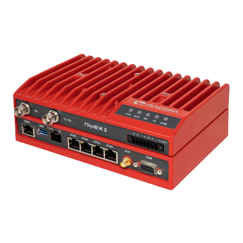
RACOM RipEX2 User manual

User manual
.
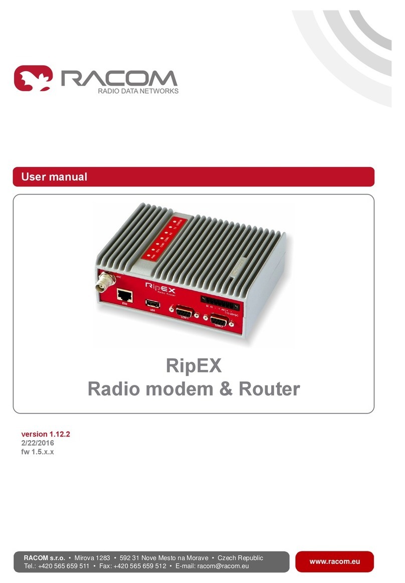
RipEX2
Radio modem & Router
.
fw 2.0.0.0
2021-03-23
version 1.11
www.racom.eu
RACOM s.r.o. | Mirova 1283 | 592 31 Nove Mesto na Morave | Czech Republic
Tel.: +420 722 937 522 | E -mail: [email protected]


Table of Contents
Important Notice .................................................................................................................................. 7
1. Quick guide ..................................................................................................................................... 8
1.1. Bench testing ...................................................................................................................... 9
2. Product .......................................................................................................................................... 11
2.1. Dimensions ......................................................................................................................... 12
2.2. Connectors ......................................................................................................................... 15
2.3. Indication LEDs .................................................................................................................. 22
2.4. Ordering codes ................................................................................................................... 24
3. Accessories ................................................................................................................................... 26
4. Installation ..................................................................................................................................... 27
4.1. Mounting ............................................................................................................................. 28
4.2. Antenna installation ............................................................................................................ 32
4.3. Antenna feed line ............................................................................................................... 33
4.4. Grounding ........................................................................................................................... 33
4.5. Connectors ......................................................................................................................... 33
4.6. Power supply ...................................................................................................................... 33
5. RipEX2 in detail ............................................................................................................................. 35
5.1. Bridge mode ....................................................................................................................... 35
5.1.1. Functionality example .............................................................................................. 36
5.1.2. Configuration examples ........................................................................................... 38
5.2. Router mode ....................................................................................................................... 39
5.2.1. Router - Base driven ................................................................................................ 39
5.2.2. Router - Flexible ...................................................................................................... 42
5.3. Combination of IP and serial communication ..................................................................... 46
5.3.1. Detailed Description ................................................................................................ 46
6. Web interface ................................................................................................................................ 48
6.1. Supported web browsers .................................................................................................... 50
6.2. Changes to commit ............................................................................................................ 50
6.3. Notifications ........................................................................................................................ 51
6.4. User menu .......................................................................................................................... 52
6.5. Help .................................................................................................................................... 52
6.6. Remote access ................................................................................................................... 53
7. Settings ......................................................................................................................................... 55
7.1. Interfaces ............................................................................................................................ 55
7.1.1. Ethernet ................................................................................................................... 55
7.1.2. Radio ....................................................................................................................... 57
7.1.2.1. Transparent protocol (Bridge mode) ............................................................. 58
7.1.2.2. Base driven protocol (Router mode) ............................................................. 60
7.1.2.2.1. Radio protocol - Base station ............................................................. 60
7.1.2.2.2. Base station - List of Remote stations ............................................... 61
7.1.2.2.3. Radio protocol - Remote station ........................................................ 62
7.1.2.3. Flexible Protocol (router mode) .................................................................... 62
7.1.2.4. Radio channel parameters ........................................................................... 63
7.1.3. COM ........................................................................................................................ 65
7.1.3.1. COM port parameters ................................................................................... 65
7.1.3.2. Common Protocol parameters ...................................................................... 67
7.1.3.3. Individual protocol parameters ..................................................................... 70
7.1.3.3.1. None .................................................................................................. 70
7.1.3.3.2. Transparent protocol .......................................................................... 70
7.1.3.3.3. Async link ........................................................................................... 70
7.1.3.3.4. DNP3 ................................................................................................. 71
3© RACOM s.r.o. – RipEX2 Radio modem & Router

7.1.3.3.5. DF1 .................................................................................................... 72
7.1.3.3.6. IEC101 ............................................................................................... 73
7.1.3.3.7. Modbus RTU ...................................................................................... 73
7.1.3.3.8. PR2000 .............................................................................................. 74
7.1.3.3.9. Siemens 3964(R) ............................................................................... 74
7.1.3.3.10. RDS ................................................................................................. 77
7.1.3.3.11. UNI ................................................................................................... 78
7.1.4. Terminal servers ...................................................................................................... 80
7.1.5. Cellular .................................................................................................................... 81
7.2. Routing ............................................................................................................................... 84
7.2.1. Static ........................................................................................................................ 84
7.2.2. OSPF ....................................................................................................................... 86
7.2.2.1. Description .................................................................................................... 86
7.2.2.2. Common - Common settings ........................................................................ 87
7.2.2.3. Network - Areas and interfaces - Areas ........................................................ 87
7.2.2.4. Network - Areas and interfaces - Interfaces ................................................. 88
7.2.2.5. Network - Areas and interfaces - Neighbors ................................................. 89
7.2.2.6. Network - Areas and interfaces - Networks .................................................. 90
7.2.2.7. Static rules .................................................................................................... 90
7.2.2.8. Import filter .................................................................................................... 91
7.2.2.9. Export filter .................................................................................................... 92
7.2.3. BGP ......................................................................................................................... 93
7.2.3.1. Description .................................................................................................... 93
7.2.3.2. Common - Common settings ........................................................................ 94
7.2.3.3. Neighbors ..................................................................................................... 95
7.2.3.4. Static rules .................................................................................................... 97
7.2.3.5. Import IGP filter ............................................................................................. 97
7.2.3.6. Export IGP filter ............................................................................................ 98
7.2.3.7. Import OUT rules .......................................................................................... 99
7.2.3.8. Export OUT filter ......................................................................................... 101
7.3. Firewall ............................................................................................................................. 102
7.3.1. Firewall L2 ............................................................................................................. 102
7.3.2. Firewall L3 ............................................................................................................. 103
7.4. VPN .................................................................................................................................. 104
7.4.1. IPsec ...................................................................................................................... 104
7.4.1.1. Advanced menu .......................................................................................... 111
7.4.2. GRE L2 .................................................................................................................. 112
7.4.3. GRE L3 .................................................................................................................. 113
7.5. Security ............................................................................................................................ 114
7.5.1. Local authentication ............................................................................................... 115
7.5.2. Remote authentication ........................................................................................... 116
7.6. Device .............................................................................................................................. 117
7.6.1. Unit ........................................................................................................................ 117
7.6.1.1. General ....................................................................................................... 117
7.6.1.2. Service USB ............................................................................................... 117
7.6.1.3. Time ............................................................................................................ 118
7.6.1.4. Hot standby ................................................................................................. 119
7.6.2. Configuration ......................................................................................................... 119
7.6.3. Events .................................................................................................................... 120
7.6.4. SNMP .................................................................................................................... 120
7.6.5. SW keys ................................................................................................................ 123
7.6.6. Firmware ................................................................................................................ 124
RipEX2 Radio modem & Router – © RACOM s.r.o.4
RipEX2
Radio modem & Router
7.7. Advanced ......................................................................................................................... 125
8. Diagnostics .................................................................................................................................. 128
8.1. Overview .......................................................................................................................... 128
8.2. Events ............................................................................................................................... 128
8.3. Statistics ........................................................................................................................... 129
8.4. Monitoring ......................................................................................................................... 135
8.5. Tools ................................................................................................................................. 142
8.6. Support ............................................................................................................................. 142
8.7. Syslog ............................................................................................................................... 143
9. Technical parameters .................................................................................................................. 144
9.1. Occupied Bandwidth limits overview ................................................................................ 153
9.2. Recommended MSE thresholds ....................................................................................... 165
10. Safety, regulations, warranty ..................................................................................................... 167
10.1. Frequency ...................................................................................................................... 167
10.2. Safety distance ............................................................................................................... 167
10.3. High temperature ............................................................................................................ 168
10.4. Battery disposal .............................................................................................................. 168
10.5. Instructions for Safe Operation of Equipment ................................................................ 168
10.6. SW license ..................................................................................................................... 169
10.7. EU Compliance .............................................................................................................. 170
10.7.1. RoHS, WEEE and WFD ..................................................................................... 170
10.7.2. EU restrictions or requirements notice ................................................................ 171
10.7.3. EU Declaration of Conformity RED ..................................................................... 172
10.7.4. Simplified EU declaration of conformity ............................................................... 172
10.8. Compliance Federal Communications Commission and Innovation, Science and Eco-
nomic Development Canada ................................................................................................... 174
10.9. Warranty ......................................................................................................................... 179
10.10. RipEX2 Availability and service life time ..................................................................... 179
10.11. RipEX2 maintenance .................................................................................................... 179
A. Abbreviations .............................................................................................................................. 181
Index ................................................................................................................................................ 183
Revision History .............................................................................................................................. 185
5© RACOM s.r.o. – RipEX2 Radio modem & Router
RipEX2
Radio modem & Router
6

Important Notice
Copyright
© 2021 RACOM. All rights reserved.
Sole owner of all rights to this User manual is the company RACOM s. r. o. (in this manual referred to
under the abbreviated name RACOM). Drawing written, printed or reproduced copies of this manual
or records on various media or translation of any part of this manual to foreign languages (without
written consent of the rights owner) is prohibited.
Products offered may contain software proprietary to RACOM. The offer of supply of these products
and services does not include or infer any transfer of ownership.
Disclaimer
Although every precaution has been taken in preparing this information, RACOM assumes no liability
for errors and omissions, or any damages resulting from the use of this information. This document or
the equipment may be modified without notice, in the interests of improving the product.
RACOM reserves the right to make changes in the technical specification or in this product function or
to terminate production of this product or to terminate its service support without previous written noti-
fication of customers.
Trademark
All trademarks and product names are the property of their respective owners.
Important Notice
• Due to the nature of wireless communications, transmission and reception of data can never be
guaranteed. Data may be delayed, corrupted (i.e. have errors), or be totally lost. Significant delays
or losses of data are rare when wireless devices such as the RipEX2 are used in an appropriate
manner within a well‐constructed network. RipEX2 should not be used in situations where failure to
transmit or receive data could result in damage of any kind to the user or any other party, including
but not limited to personal injury, death, or loss of property. RACOM accepts no liability for damages
of any kind resulting from delays or errors in data transmitted or received using RipEX2, or for the
failure of RipEX2 to transmit or receive such data.
• Under no circumstances is RACOM or any other company or person responsible for incidental, acci-
dental or related damage arising as a result of the use of this product. RACOM does not provide the
user with any form of guarantee containing assurance of the suitability and applicability for its
application.
• RACOM products are not developed, designed or tested for use in applications which may directly
affect health and/or life functions of humans or animals, nor to be a component of similarly important
systems, and RACOM does not provide any guarantee when company products are used in such
applications.
7© RACOM s.r.o. – RipEX2 Radio modem & Router
Important Notice

1. Quick guide
RipEX2 is a widely configurable compact radio modem, more precisely a radio IP router. All you have
to do to put it into operation is to connect it to an antenna and a power supply and configure it using a
PC (tablet, smartphone) and a web browser.
Fig. 1.1: Connecting RipEX2 to a PC over WiFi, ETH/USB adapter, ETH interface
Default password for "admin" account is "admin". Change the password before deploying unit
to a network.
To configure RipEX2 you can connect it to your PC in three ways:
•PC (tablet, smartphone) connected via WiFi adapter
External WiFi adapter Part No. OTH-USB/WIFI-W2 (an optional accessory of the RipEX2 see
ETH/USB adapter1) needs to be used. Any other adapter will not work correctly when connected to
RipEX2 unit. Connect your PC, tablet or smartphone to RipEX2 WiFi AP first. Its default SSID is
RipEX2 S/N. By default, the WPA2 PSK is disabled, so no password is required. The WiFi adapter
contains a built-in DHCP server, so if you have a DHCP client in your PC (as most users do), you
do not need to set anything up. The default IP address of RipEX2 unit, for access over the ETH/USB
adapter, is 10.9.8.7.
•PC connected via ETH/USB adapter
External ETH/USB adapter Part No. OTH-USB/ETH-XR (an optional accessory of the RipEX2 see
ETH/USB adapter2). The ETH/USB contains a built-in DHCP server, so if you have a DHCP client
in your PC as most users, you do not need to set anything up. The default IP address of RipEX2
unit, for access over the ETH/USB adapter, is 10.9.8.7.
1https://www.racom.eu/eng/products/radio-modem-ripex.html#accessories_ethusb
2https://www.racom.eu/eng/products/radio-modem-ripex.html#accessories_ethusb
RipEX2 Radio modem & Router – © RACOM s.r.o.8
Quick guide

•PC connected directly to an ETH port
The default IP address for access via ETH ports is 192.168.169.169.
Set a static IP address in PC to 192.168.169.0/24 (e.g.192.168.169.250, subnet mask 255.255.255.0).
Important
When you change the RipEX2 ETH address to a different IP address/mask, the IP address
of your PC might be necessary to be updated to match the same subnet (mask).
Note
https - For security reasons the http protocol with ssl encryption can be used for the commu-
nication between the PC and RipEX2. The https protocol requires a security certificate. You
must install this certificate into your web browser. The first time you connect to the RipEX2,
your computer will ask you for authorisation to import the certificate into your computer. The
certificate is signed by the certification authority RACOM s.r.o. It meets all security regulations
and you need not to be concerned about importing it into your computer. Confirm the import
with all warnings and exceptions that your browser may display during installation.
Warning
Before you start any configuration, make sure only one unit is powered ON, otherwise a different
radio modem could reply to your requests! (In default settings: all units share the same IP ad-
dress and are in Bridge mode - which means, they can connect together over the air and create
unwanted responds.)
Note
If you do not have the USB adapter or you have forgotten the password, you can reset the
access parameters to defaults, see Section 2.2.9, “HW button”.
1.1. Bench testing
Before installing a RipEX2 network in the field, a bench-test should be performed in the lab. The RipEX2
Demo case is great for this as it contains everything necessary: 3× RipEX2 unit, Power supply, dummy
load antennas, etc.
If you use your own installation for lab tests, do not forget:
• A dummy load or an actual antenna with 50 ohm impedance should be connected to the RipEX2
• Minimum RF output must be set to avoid overloading the dummy antenna and to keep the received
signal at reasonable level, between -40 and -80 dBm.
• The power supplies must meet the requirements given in the specifications. Make sure the power
supplies do not generate interference in the radio channel and that they can handle very fast changes
in the load when RipEX2 switches from reception to transmission and back.
9© RACOM s.r.o. – RipEX2 Radio modem & Router
Quick guide

Fig. 1.2: RipEX2 bench testing
RipEX2 Radio modem & Router – © RACOM s.r.o.10

Quick guide

2. Product
RipEX2 is a radio modem platform renowned for overall data throughput in any real-time environment.
RipEX2 radio modems are native IP devices, Software Defined with Linux OS that have been designed
with attention to detail, performance and quality.
RipEX2 is built into a rugged die-cast aluminium casing that allows for multiple installation possibilities,
see Section 4.1, “Mounting”.
11© RACOM s.r.o. – RipEX2 Radio modem & Router
Product

2.1. Dimensions
125,5
134,7
185
31,7
62,7
93,7
42
92,5
143
M4 (4x)
60
67
7
60
67
max. depth 6mm
Fig. 2.1: RipEX2 dimensions
RipEX2 Radio modem & Router – © RACOM s.r.o.12
Product

31,7
62,7
93,7
125,5
42
92,5
143
185
M4 (4x)
max.depth 8 mm
Fig. 2.2: RipEX2 dimensions – bottom
60
68,3
185
DIN 35 Rail
DIN Rail Clip
68,3
134,7
125,5
Fig. 2.3: RipEX2 with DIN rail
13© RACOM s.r.o. – RipEX2 Radio modem & Router
Product

2.2. Connectors
All connectors are located on the front panel. The upper side features a LED panel. The HW button is
located on the front panel as well (close to the COM connector).
Fig. 2.5: Connectors
2.2.1. Antenna
Fig. 2.6: Antenna connectors
An antenna can be connected to
RipEX2 via TNC female 50Ω connector.
RipEX2 is equipped with two connect-
ors. The Tx/Rx connector will be used
for common transmitting and receiving
single antenna installation (even with
different Rx and Tx frequencies).
Both Rx and Tx/Rx connectors for split
installation (two antennas or duplex operation with duplexer) - Rx for receiving and Tx/Rx for transmitting.
Warning
RipEX2 radio modem may be damaged when operated without an antenna or a dummy load.
15© RACOM s.r.o. – RipEX2 Radio modem & Router
Product

2.2.2. Power and Control
This rugged connector connects to a power supply and it contains control signals. A Plug with screw-
terminals and retaining screws for power and control connector is supplied with each RipEX2. It is Tyco
7 pin terminal block plug, part No. 1776192-7, contact pitch 3.81 mm. The connector is designed for
electric wires with a cross section of 0.5 to 1.5 mm2. Strip the wire leads to 6 mm (1/4 inch). Isolated
cables should receive PKC 108 or less end sleeves before they are inserted in the clip. Insert the cables
in the wire ports, tightening securely.
Tab. 2.1: Pin assignment
SignalLabeledPin
SLEEP INPUT
SI1 • pull below 1.1 VDC to activate (1.1 VDC / 1.9 VDC
threshold hysteresis)
• max. 30 VDC
HW ALARM INPUT
AI2 • pull below 1.1 VDC to activate (1.1 VDC / 1.9 VDC
threshold hysteresis)
• max. 30 VDC
−(GND) – for SLEEP IN, HW ALARM INPUT−3
+(POWER) – for HW ALARM OUTPUT+4
HW ALARM OUTPUT
open drain output max. 30 VDC, 1 A
AO5
+ POWER (10 to 30 V)
Undervoltage threshold 8.5 VDC
Overvoltage threshold 41 VDC
+6
− POWER (GND)−7
Pins 3 and 7 are connected internally.
Pins 4 and 6 are connected internally.
Fig. 2.7: Supply connector
Wire
Ports (7)
Retaining
Screws (2)
Lead
Binding
Screws (7)
Fig. 2.8: Power and Control - cable plug
RipEX2 Radio modem & Router – © RACOM s.r.o.16
Product

1 2 3 4 5 6Pin No.: 7
SI AI - + A0 +-
10–30VDC
Alarm Input
HW ALARM INPUT
HW ALARM INPUT is a digital input. If grounded (e.g. by connect-
ing to pin 3), an external alarm is triggered.
1 2 3 4 5 6Pin No.: 7
SI AI - + A0 +-
10–30VDC
Alarm Output
max. 30 V DC, 1 A
HW ALARM OUTPUT
HW ALARM OUTPUT is a digital output.
POWER
The POWER pins labelled + and - serve to connect a power supply 10–30 VDC. The requirements for
a power supply are defined in Section 4.6, “Power supply” and Chapter 9, Technical parameters.
17© RACOM s.r.o. – RipEX2 Radio modem & Router

Product

2.2.3. ETH1 - ETH4
Standard RJ45 connectors for Ethernet connection. RipEX2 has 10/100/1000Base-T Auto MDI/MDIX
interfaces so it can connect to 10 Mb/s, 100 Mb/s or 1000 Mb/s Ethernet network. The speed can be
selected manually or recognized automatically by RipEX2. RipEX2 is provided with Auto MDI/MDIX
function which allows it to connect over both standard and cross cables, adapting itself automatically.
Pin assignment
Tab. 2.2: Ethernet to cable connector connections
Crossed cableDirect cableSignalPin
green – whiteorange – whiteTX+1
greenorangeTX−2
orange – whitegreen – whiteRX+3
blueblue—4
blue – whiteblue – white—5
orangegreenRx−6
brown – whitebrown – white—7
brownbrown—8
2.2.4. ETH5 (SFP)
Fig. 2.9: SFP slot
ETH5 is a standard SFP slot for 10/100/1000 Mb/s Ether-
net SFP modules, user exchangeable with maximal power
consumption 1.25 W. Both fibre optic and metallic Ether-
net SFP modules are supported. For optical both single
and dual mode fibre optics Ethernet modules (= 2 or 1
fibers) can be used. CSFP modules are not supported.
RACOM offers all mentioned types of SFP modules,
tested to be RipEX2 compatible as a standard accessory.
The SFP status LED is located just next to the slot. It is
controlled by SFP module. Its function is specific for each
SFP module. The typical behavior is an indication the re-
ceived signal from the fibre optic or metallic link to be
within operational range.
Important
It is strongly recommended to use a high quality SFP module with industry temperature range.
The SFP modules listed in Accessories are thoroughly tested by RACOM and are guaranteed
to function with RipEX2 units. It is possible to use any other SFP module, but RACOM cannot
guarantee they will be completely compatible with RipEX2 units.
RipEX2 Radio modem & Router – © RACOM s.r.o.18
Product

2.2.5. COM
RipEX2 provides serial interface COM terminated by DSUB9F connectors. It can be configured as
RS232 or RS485.
RS232 of RipEX2 is a hard-wired DCE (Data Communication Equipment) device. Equipment connected
to the serial port of RipEX2 unit should be DTE (Data Terminal Equipment) and a straight-through cable
should be used. If a DCE device is connected to the serial port of RipEX2, a null modem adapter or
cross cable has to be used.
RS485 of RipEX2 is not galvanic isolated and it is not terminated.
Tab. 2.3: COM pin description
COM – RS485COM – RS232DSUB9F
In/ OutSignalIn/ OutSignalPin
—OutCD1
In/Outline BOutRxD2
In/Outline AInTxD3
—InDTR4
GNDGND5
—OutDSR6
—InRTS7
—OutCTS8
———9
RipEX2 keeps pin 6 DSR at the level of 1 by RS232 standard permanently.
Expansion board 'C' (2 x RS232)
The 2nd and 3rd COM ports are available when the Expansion board 'C' (2 x RS232) is installed. In
such a case: The DI/DO connector is used as a connector for COM2 and COM3.
COM2 and COM3 parameters:
• COM2: RS232 - 5 pin (RxD, TxD, GND, RTS, CTS) 300 b/s to 2 Mb/s
• COM3: RS232 -3 pin (RxD, TxD, GND) 2.4 kb/s to 921.6 kb/s
Tab. 2.4: DI/DO output
SignalPin
RxD COM31
TxD COM32
GND3
CTS COM24
RTS COM25
GND6
19© RACOM s.r.o. – RipEX2 Radio modem & Router

Product

SignalPin
RxD COM27
TxD COM28
This interface is not compatible with RipEX2-HS.
If the RipEX2 unit is installed in the RipEX2-HS (Hot Standby chassis), the DI/DO interface is dedicated
for the Hot Standby operation.
2.2.6. USB
RipEX2 uses USB 3.0, Host A interface. USB interface is wired as standard:
Tab. 2.5: USB A Pinout Cable Assembly
WireSignalPin
RedVBUS1
WhiteD-2
GreenD+3
BlackGND4
BlueStdA_SSRX-5
YellowStdA_SSRX+6
GROUNDGND_DRAIN7
PurpleStdA_SSTX-8
OrangeStdA_SSTX+9
Connector ShellShieldShell
The USB interface is designed for the connection to an external ETH/USB adapter or a WiFi adapter.
They are optional accessories to RipEX2, for more details see www/ripex/accessories1. The adapters
are used for service access to web configuration interface of RipEX2 unit.
The USB connector also provides power supply (5 V / 0.5 A). It can be used to temporarily power a
connected device, for instance a telephone. The USB connector should not be used as permanent
source of power supply.
2.2.7. AUX
Fig. 2.10: AUX connector SMA
AUX SMA female 50 Ohm connector is used for several
purposes according to HW variant.
Standard basic model – the AUX is used as an synchron-
ization signal input.
Input frequency range 1 Hz (PPS) - 25 MHz
Input signal level >200 mVp-p @ 220R, up to 5V TTL
levels
1https://www.racom.eu/eng/products/radio-modem-ripex.html#accessories_ethusb
RipEX2 Radio modem & Router – © RACOM s.r.o.20
Product
Other manuals for RipEX2
3
This manual suits for next models
5
Table of contents
Other RACOM Radio Modem manuals

RACOM
RACOM RAy3 User manual

RACOM
RACOM RipEX2 User manual

RACOM
RACOM RipEX2-HS User manual

RACOM
RACOM ECONOMY RE400 User manual

RACOM
RACOM RipEX 1.4 User manual

RACOM
RACOM PROFI MR300 User manual

RACOM
RACOM RipEX 1.5 User manual

RACOM
RACOM RipEX 1.12.2 User manual

RACOM
RACOM RipEX User manual

RACOM
RACOM RipEX User manual