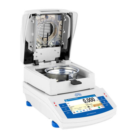
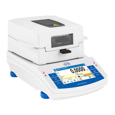
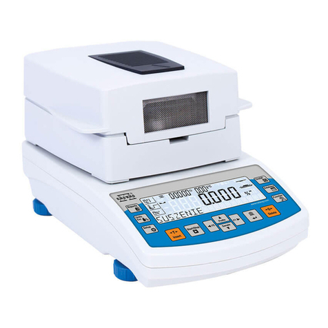
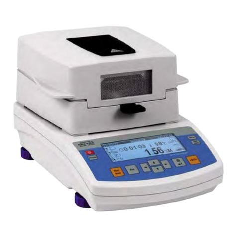
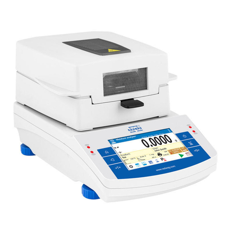
RADWAG MA 3Y User manual

MA 3Y
Moisture Analyzer
IMMU-10-09-11-17-EN
www.radwag.com
USER MANUAL

- 2 -
NOVEMBER 2017

- 3 -
Table of contents
1. TECHNICAL SPECIFICATION ............................................................. 7
2. GENERAL SAFETY INFORMATION...................................................... 8
2.1. Definitions of signals and warning signs ................................................... 8
2.1.1 Warning descriptions .................................................................................. 8
2.1.2 Warning signs ............................................................................................ 8
2.2. Safety information .................................................................................. 9
2.3. Intended use ...................................................................................... 10
2.4. Inappropriate use................................................................................ 11
2.5. Principles of safety use ........................................................................ 11
2.6. Warranty ........................................................................................... 12
2.7. Monitoring metrological parameters of the instrument .............................. 12
2.8. Data included in this user manual .......................................................... 12
2.9. Staff competence ................................................................................ 13
2.9.1. Protective clothing .......................................................................... 13
3. TRANSPORT AND STORAGE............................................................. 14
3.1. Delivery check .................................................................................... 14
3.2. Packaging .......................................................................................... 14
4. UNPACKING, ASSEMBLING AND STARTUP ...................................... 14
4.1. Assembling and place of use ................................................................. 14
4.2. Unpacking .......................................................................................... 15
4.3. Level setting ...................................................................................... 16
4.4. Standard delivery components .............................................................. 16
4.5. Cleaning ............................................................................................ 17
4.6. Plugging to mains ............................................................................... 17
4.7. Connecting peripheral equipment .......................................................... 17
4.8. Interfaces ........................................................................................... 17
4.9. Balances with a wireless connection between the terminal and the weighing
module (an option) ..................................................................... 18
5. STARTUP......................................................................................... 21
5.1. Temperature stabilization period of time .................................................. 22
5.2. Moisture analyzer switching off ............................................................. 22
6. KEYBOARD – FUNCTION KEYS......................................................... 22
7. SOFTWARE STRUCTURE .................................................................. 24
8. SOFTWARE MAIN WINDOW ............................................................ 25
8.9. Weighing window ................................................................................ 25
8.10. Drying window .................................................................................... 26
8.11. Drying result ...................................................................................... 27
9. LOGGING ........................................................................................ 28
10. OPERATING USER MENU ................................................................. 30
10.1. Terminal’s keyboard ............................................................................ 30
10.2. Return to weighing mode ..................................................................... 31
11. WEIGHING...................................................................................... 31
11.1. Selection of measuring unit .................................................................. 31

- 4 -
11.2.Means of correct weighing procedure ..................................................... 32
11.3. Leveling ............................................................................................. 33
11.4. Zeroing ............................................................................................. 34
11.5. Tarring .............................................................................................. 34
11.6. Additional parameters on weighing process ............................................. 35
11.7. Minimum Sample Weight ...................................................................... 37
11.8. Cooperation with titrators ..................................................................... 41
12. ADJUSTMENT .................................................................................. 42
12.1. External adjustment ............................................................................ 42
12.2. User adjustment ................................................................................. 43
12.3. Temperature adjustment ...................................................................... 43
12.5. Adjustment report printout ................................................................... 50
12.6. GLP project ........................................................................................ 50
12.7. Adjustment history .............................................................................. 50
13. USERS............................................................................................. 52
14. ACCESS LEVEL................................................................................. 53
15. PROFILES........................................................................................ 55
15.1. Creating a profile ................................................................................ 55
15.2. Profile structure .................................................................................. 56
15.3. Settings ............................................................................................. 57
15.4. Working modes ................................................................................... 57
15.5. Readout ............................................................................................. 57
15.6. Measuring units .................................................................................. 59
16. WORKING MODES – general information ........................................ 60
16.1. Working mode selection ....................................................................... 60
16.2. Parameters related to a working mode ................................................... 61
16.3. Quick access keys ............................................................................... 61
16.3.1. Proximity sensors ................................................................................ 62
16.4. Information ........................................................................................ 62
16.5. Printouts ............................................................................................ 63
16.6. Profiles .............................................................................................. 65
17. DRYING PROCESS – GENERAL INFORMATION ................................ 65
SAMPLE PREPARATION FOR DRYING .............................................................. 66
17.1.1. Means of moisture content measurement on a moisture analyzer ............... 66
17.1.2. Sampling and preparation ..................................................................... 66
17.1.3. Sample distribution on drying pan: ........................................................ 68
17.2. SELECTION OF DRYING PARAMETERS .................................................... 69
17.2.1. Selecting optimum sample mass ............................................................ 69
17.2.2. Influence of sample mass on measurement result repeatability .................. 69
17.2.3. Drying temperature ............................................................................. 69
17.2.4. Selecting drying mode .......................................................................... 70
17.2.5. Drying time ........................................................................................ 71
18. DRYING PROCESS ........................................................................... 72
18.1. Working mode activating procedure ....................................................... 72
18.2. Setting drying parameters .................................................................... 73
18.2.1. Using fields visible in the main display section ......................................... 73
18.2.2. Use of menu <Settings> ...................................................................... 79
18.2.3. Using database of drying programs ........................................................ 82

- 5 -
18.3. Printouts in drying mode ...................................................................... 83
18.4. Report from completed drying process ................................................... 86
18.5. Means of carrying out drying process ..................................................... 87
18.6. Chart of drying process ........................................................................ 92
19. DATABASES..................................................................................... 94
19.1. Processes carried out on databases ....................................................... 95
19.2. Products ............................................................................................ 96
19.3. Weighing records ................................................................................ 97
19.4. Clients ............................................................................................... 98
19.5. Drying program .................................................................................. 99
19.6. Reports from drying process (Drying reports) .......................................... 99
19.7. Statistics from drying process reports ................................................... 101
19.8. Minimal sample weight ........................................................................ 103
19.9. Ambient conditions ............................................................................. 104
19.10. Packages ...................................................................................... 105
19.11. Warehouses .................................................................................. 105
19.12. Printouts ....................................................................................... 106
19.13. Universal variables ......................................................................... 108
19.14. Database operation ........................................................................ 108
19.14.1. Export database of weighing records to file........................................... 109
19.14.2. Delete database ............................................................................... 110
19.14.3. Delete weighments and reports .......................................................... 111
20. COMMUNICATION ......................................................................... 113
20.1. RS 232 port settings ........................................................................... 113
20.2. ETHERNET port settings ...................................................................... 113
20.3. WiFi settings ..................................................................................... 114
20.4. TCP protocol settings .......................................................................... 115
21. PERIPHERAL DEVICES .................................................................. 117
21.1. Computer ......................................................................................... 117
21.2. Printer .............................................................................................. 118
21.3. Barcode scanners ............................................................................... 119
21.3.1. Barcode Scanner’s Port ...................................................................... 120
21.3.2. Prefix/Suffix ........................................................................................ 120
21.3.2. Field Selection .................................................................................. 120
21.3.3 Test .................................................................................................... 122
21.4. Transponder card scanner ................................................................... 122
21.5. Additional display ............................................................................... 123
22.INPUTS / OUTPUTS....................................................................... 124
23. OTHER PARAMETERS..................................................................... 126
23.1. Interface language ............................................................................. 126
23.2. Data and time setting ......................................................................... 126
23.3. “Beep” sound .................................................................................... 127
23.4. Volume ............................................................................................. 127
23.5. Sleep mode ....................................................................................... 127
23.6. Display brightness .............................................................................. 127
23.7. Touch screen display calibration ........................................................... 128
23.8. Level control ..................................................................................... 128
23.9.Drying temperature reducing ............................................................... 129
- 6 -
23.10. Compatibility with MAC/MAX series ................................................... 129
23.11. Sensors sensitivity ......................................................................... 130
23.12. Proximity sensors delay .................................................................. 130
23.13. Autotest ....................................................................................... 130
23.14. Start logo ..................................................................................... 131
23.15. Export system events ..................................................................... 131
24. UPDATE......................................................................................... 131
25. SYSTEM INFORMATION................................................................. 132
26. MOVIES......................................................................................... 133
27. COMMUNICATION PROTOCOL ....................................................... 135
27.1. A set of commands ............................................................................. 135
27.2. Responses format for commands sent from computer level ...................... 137
27.3. Manual printout / Automatic printout .................................................... 150
28. CONNECTING PERIPHERAL DEVICES............................................. 151
29. DIAGRAMS OF CONNECTING CABLES ............................................ 151
30. ERROR MESSAGES......................................................................... 152
31. MOISTURE ANALYZER MAINTENANCE ACTIVITIES ....................... 153
31.1. Cleaning moisture analyzer components ................................................ 153
31.2. Temperature sensor cleaning ............................................................... 154
31.3. Replacing the fuses ............................................................................ 155
31.4. Troubleshooting ................................................................................. 156
32. ADDITIONAL EQUIPMENT............................................................. 157
33. APPENDIX A – Variables for printouts........................................... 158
33.1. List of variables ................................................................................. 158
33.2. Variables formatting ........................................................................... 167
34. APPENDINX E -Settings of ZEBRA printers.................................. 169
35. APPENDIX F – Communication with barcode scanners.................. 170
36. APPENDIX G – Menu structure...................................................... 171

- 7 -
1. TECHNICAL SPECIFICATION
Type MA 60.3Y MA 200.3Y
Reading unit
0.1 mg
1 mg
Max. capacity
60 g
200 g
Moisture reading
accuracy
0,0001% 0,001%
Tare range
- 60 g
- 200 g
Max. sample
mass
60 g 200 g
Repeatability of
moisture content
reading
+/-0,05% (sample ~ 2g), +/-0,01% (sample ~10g)
Heating module
Halogen
Infrared emitter
Metal heater
Drying
temperature
range
Max 160 °C (infrared emitter or metal heater)
Max 250 °C (halogen)
Drying modes
4 modes: standard, quick, step, mild
Auto switch off
option
4 modes: time-defined, defined, automatic, manual
Working
temperature
+10 °C ÷ +40 °C
Power supply
230V 50Hz AC / 420W
Display
Touch screen display
Drying chamber
dimensions
120 x 120 x 20 mm
Net weight /
gross weight
6 / 10 kg
Packaging
dimensions
595 x 395 x 420 mm

- 8 -
2. GENERAL SAFETY INFORMATION
2.1. Definitions of signals and warning signs
Safety precautions are marked with special descriptions and warning signs. They inform
and warn a user of possible dangers. Ignoring the safety warnings may cause injuries,
damage of the moisture analyzer, its inappropriate operation and errors of
measurements.
2.1.1 Warning descriptions
WARNING
Dangerous situations of high risk. These situations can cause
serious injuries or death if the safety precautions are not
taken.
CAUTION
Dangerous situations of low risk. These situations can cause
damage of the instrument or its functions, loss of data as well
as minor or moderate body injuries.
ATTENTION
Important information related to the moisture analyser.
2.1.2 Warning signs
Electric shock risk
Acid / Corrosion
Danger
Flammable or explosive substances
Toxic substances
Hot surfaces

- 9 -
2.2. Safety information
CAUTION!
The use of moisture analyzer MA 3Y regardless of both, safety
information and user manual guidelines may cause health damage
and even death
WARNING:
Nominal voltage for a moisture analyzer is 230 VAC. It means
that safety usage precautions for low voltage devices must be
abide by while operating the device.
Three-core power supply cable with grounding pin comes
standard with a moisture analyzer.
If necessary, an extension cord can be used as long as it meets
the applicable standards and has a protective ground conductor.
Intended disconnection of the grounding cable is forbidden.
CAUTION:
Drying chamber cannot be opened during operation (drying
process). It is due to the fact that a halogen lamp and its glass
shield may reach the temperature of up to 400 C.
When setting up the moisture analyzer leave enough space to
prevent heat from building up and to keep your analyzer from
overheating. Leave about 20 cm around the instrument and
about 1 m above.
Air vents that are located in the housing cannot be covered,
sealed or blocked in any other way.
Do not put any flammable substances on, under or near the
moisture analyzer.
Be particularly careful when removing the sample from the
drying chamber: the sample itself, the drying chamber, shields
and the pan can still be extremely hot.
In case of any maintenance work (cleaning the inside of the
drying chamber), the moisture analyzer must be switched off.
Wait until all the components have cooled down. Do not perform
any modification to the heating module.
Same types of samples require taking particular safety
precautions.
They can pose a danger for people and objects. It is
always the user
who is liable for possible damages caused by the use of an
inappropriate sample.
CAUTION:

- 10 -
Corrosion
Substances that release aggressive vapours (e.g. acids) during
the heating process. In this case, it is recommended to work
with
small samples. Otherwise, vapours can condense on cold
housing parts and cause corrosion.
WARNING:
Fire or explosion
Flammable or explosive substances, substances containing
solvents or releasing flammable or explosive gases or vapours.
Perform a risk analysis when in doubt relating to the sample
characteristics before carrying out the procedure.
For this type of samples apply the drying temperatures as low
as possible to prevent flames or explosion. During the analysis it
is
necessary to wear protective glasses and gloves. The samples
should be relatively small.
Under no circumstances can the instrument be left
Unsupervised!
WARNING:
Substances containing toxic and caustic or corrosive
components
Substances that release toxic gases or vapours can cause
irritations (eyes, skin or respiratory system), illnesses or even
death. Dry such substances only in fume hood.
Under no circumstances should the instrument be used in an area with
any
risk of explosion. The moisture analyzer is not designed to operate in
hazardous areas.
2.3. Intended use
A moisture analyzer MA 3Y series is designed to determine relative moisture
content in small samples of various substances, determine dry mass content
in small samples and determine mass of weighed objects.
MA 3Y ensures fast and precise determination process of water content in a
tested sample, and application of touch screen display considerably simplifies
operation and improves functionality of the moisture analyzer. A moisture
analyzer MA 3Y series can be used to determine humidity content of different
materials.

- 11 -
At the initial stage of measurement, the device precisely determines the mass
of an object placed on instrument’s weighing pan. As the mass reading is
stabilized, the sample is quickly heated by a halogen lamp, an IR emitter or a
metal heater causing humidity evaporation from the tested sample. While
sampling, the moisture analyzer is continuously checking the loss of mass,
and on calculation, it displays current moisture content in a tested sample.
Compared to conventional methods of humidity content determination of
various substances, application of moisture analyzer MA 3Y series
considerably shortens measurement time and simplifies testing procedure. MA
3Y series allows for setting multiple parameters which influence the procedure
of moisture content determination in a sample, such as: temperature, time,
drying modes, etc.
2.4. Inappropriate use
CAUTION!
Do not open the drying chamber during drying process. Moisture analyzer
features a halogen lamp which is a very powerful heat source. Thus, user
should pay special attention no to touch those elements of a moisture
analyzer that get hot while drying procedure (i.e.: disposable pan, pan
handle, and inner shields of the drying chamber).
Remember that some of tested samples may become dangerous if heated
(appearance of poisoning vapours, danger of ignition or explosion).
Moisture analyzer MA 3Y series is not intended for dynamic weighing. Even if
small amounts of a sample are added to taken off the weighing pan, the mass
readout should only be taken only on stabilization of measurement result
(appearance of stability pictogram on the display).
Do not place any magnetic materials on the weighing pan, as this can cause
damage of the measuring system of the instrument. Be sure to avoid impact
shock and overloading the moisture analyzer in excess of the prescribed
maximum measuring range (max capacity), minus any possible tare weight
that has been applied).
Never use the moisture analyzer in an environment endangered by an
explosion.
This moisture analyzer is not adjusted for operation in explosive areas. There
must not be any modification made to the moisture analyzer.
2.5. Principles of safety use
Moisture analyzer is in accord with all binding safety regulations. Nevertheless
there are exceptional circumstances that may cause danger.
It is forbidden to open an instrument housing. Inside there are no parts that
would require maintenance, repair or replacement carried out by a user. In

- 12 -
case of any problems it is recommended to contact RADWAG service or a
distributor. It must be always remembered to use the device in accordance
with this service manual and especially to follow instructions on installation
and configuration of a new device.
Use of a moisture analyzer MA 3Y series conversely to safety principles and
user manual guidelines may be hazardous to operator’s health and life. It is
obligatory to acknowledge the safety principles listed in the user manual:
- use a moisture analyzer only to determine humidity content in samples and
determine mass of a tested sample. Any other use of the moisture analyzer
may be dangerous both to the device and the user,
- before commissioning the moisture analyzer, make sure that the nominal
power of the device specified on its data plate, is compatible with the
supply in the mains to which the moisture analyzer will be plugged in,
- change of halogen lamps can only be carried out by authorized
service,
- protect moisture analyzer against contacts with liquids, it might lead to
electrocution, fire, emission of substances containing toxic or caustic
vapour, emission of explosive substances.
2.6. Warranty
Warranty does not cover the following cases:
•Not observing the regulation listed in user manual,
•Using the moisture analyzer conversely to its intended use,
•Any modifications of moisture analyzer or cases when its housing is
opened (damaged protective stickers),
•Mechanical defects and defects caused by media, liquids, water and
natural wearing off,
•Improper placing of defects of electrical network / mains,
•Overloading of measuring mechanism of the moisture analyzer.
2.7. Monitoring metrological parameters of the instrument
Metrological characteristics of the moisture analyzer requires periodical
inspection carried out by its operator. Inspection frequency is conditioned by
ambient conditions in which the moisture analyzer is used, types of performed
processes and accepted quality management system in an organization.
2.8. Data included in this user manual

- 13 -
Please read the user manual carefully before instrument’s plugging to mains
and startup, even if the user is experienced with this type of moisture
analyzers.
2.9. Staff competence
Moisture analyzer MA 3Y series should only be operated and maintained by
personnel who is trained and experienced in using this type of instruments.
In order to use the moisture analyzer, first read the user manual. Keep these
instructions for the future reference.
Do not make any structural modifications. Additional equipment, which can be
connected to the moisture analyzer, should be supplied by RADWAG or an
authorized distributor.
2.9.1. Protective clothing
The use of protective clothing is highly recommended while working with the
instrument in order to take safety precautions against potential hazards
resulting from tested samples and ingredients.
Use the following while carrying out tests:
•protective apron,
•protective glasses,
•protective gloves (while working with hazardous chemical substances).
Before the use of the above-mentioned protective clothing, make sure that
they are designed to be used with specific samples and they are not damaged.

- 14 -
3. TRANSPORT AND STORAGE
3.1. Delivery check
Please check the packaging immediately upon delivery and check instrument’s
condition directly upon unpacking for any visible signs of external damage.
3.2. Packaging
Please retain all parts of the original packaging should the moisture analyzer
be transported in the future. Only the original packaging should be used for
dispatching the moisture analyzer. Before packing, disconnect all attached
cables and remove any loose/movable parts (weighing pan, shields, inserts).
Place moisture analyzer and its components in their original packaging, and
protect them against damage during transport.
4. UNPACKING, ASSEMBLING AND STARTUP
4.1. Assembling and place of use
•A moisture analyzer should be stored and used in locations free of
vibrations and shakes, free of air movement and dust, located at the max
altitude of 2000 above sea level,
•Moisture analyzer’s place of use should ensure good air circulation around
the instrument (approximately 20 cm fee space around the moisture
analyzer and 1 m free space over it),
•Ambient air temperature in the weighing room should not exceed the
range of:
+10 °C ÷ +40 °C,
•Ambient relative humidity should not exceed 80% in the temperature up to
31°C, and decrease linearly to 50 % of relative humidity in temperature
40°C,
•A moisture analyzer should be located on a stable wall console desk or a
stable working table which is not affected by vibrations and distant from
heat sources,
•Take special safety measures when weighing magnetic objects, as part of
the balance is a strong magnet.

- 15 -
4.2. Unpacking
Carefully remove the moisture analyzer from its packaging, remove the
plastic and foil transport protective elements. Gently place the moisture
analyzer in its intended place of use.
Assembly the components of drying chamber, following guidelines from below
figure:
Assembling moisture analyzer components:
1. Assembly drying chamber
base insert
2. Assembly drying pan shield,
3. Assembly drying pan handle,
4. Assembly cross-shaped
holder,
5. Assembly the disposable pan.
Setting drying pan’s supporter (cross-shaped holder).

- 16 -
When assembling the pan
supporter (cross-shaped holder)
pay special attention to the
correct positioning of its
mandrel. The mandrel features a
cut for its unique positioning
against the pan handle, thus
preventing their contact and
friction.
Setting cross-shaped holder:
-On assembling the pan holder
onto the mandrel, turn the
holder slightly, so that the cut
on the mandrel is located in
its unique and correct
position,
-When turning the mandrel use
most gentle movements not
to damage moisture
analyzer’s measuring system.
4.3. Level setting
The moisture analyzer MA 3Y series features an electronic level control
system (and thus no external level). After software startup enter the leveling
application and follow moisture analyzer prompts to carry out the leveling
procedure.
Means of moisture analyzer leveling is described further in this user manual
(see point 11.3).
4.4. Standard delivery components
•A moisture analyzer MA 3Y series.
•Insert of drying chamber basis.
•Drying chamber shield.
•Drying pan handle.
•Drying pan cross-shaped holder.
•Disposable pan.
•Power cord.
•Protective cover
•Cable P0108 for connecting moisture analyzer and computer
•User manual (CD).

- 17 -
4.5. Cleaning
Remember to unplug the moisture analyzer from mains before any
cleaning activities.
Clean the moisture analyzer using a damp cloth by gentle rubbing
contaminated places.
Remember to remove the drying pan from the drying chamber before
its cleaning. Cleaning the drying pan assembly while installed may
damage instrument’s measuring system, thus remove it from the cross-
shaped holder.
4.6. Plugging to mains
A moisture analyzer can be plugged to mains only by means of
original power cord, which comes standard with the moisture
analyzer. Rated voltage (specified on device’s data plate) must be
compatible with mains rated voltage.
The power cord can be connected only to a socket with ground contact. Plug
the power cord to the moisture analyzer. The moisture analyzer’s power plug
is located at the back of its housing.
4.7. Connecting peripheral equipment
The moisture analyzer must be unplugged from the mains before connecting
or disconnecting any peripheral equipment (printer, PC computer). Use only
peripheral equipment recommended by the manufacturer with your moisture
analyzer. These have been ideally coordinated to your moisture analyzer. On
connecting a peripheral device, plug the moisture analyzer to mains.
4.8. Interfaces
Description of terminal’s interfaces
1 – Ethernet RJ45
2 – RS232 (COM1)
3 – USB port
4 – IN/OUT, RS232 (COM2)
Interface RS232 and IN/OUT

- 18 -
RS232 - socket DB9/M (male), front view:
Pin2 - RxD
Pin3 - TxD
Pin5 - GND
IN/OUT, RS232 socket DSUB15/F (female), front view:
Pin1 - GNDWE
Pin2 - OUT1
Pin3 - OUT2
Pin4 - COMM
Pin5 - 6÷9VDC
Pin6 - IN4
Pin7 - IN3
Pin8 - TxD2
Pin9 - 5VDC
Pin10 - GNDRS
Pin11 - IN2
Pin12 - IN1
Pin13 - RxD2
Pin14 - OUT4
Pin15 - OUT3
4.9. Balances with a wireless connection between the terminal and
the weighing module
(an option)
The terminal operates on bateries, wireless connection ensures its cooperation
with the weighing module. This, in contrast to a standard design, allows to
eliminate cable connecting the devices.
Wireless connection solution is marked by letter <B>, eg. MA 50.3Y.B.
Features:
Maksimum range: 10 m
Maxumum operation time of the terminal (without the necessity to charge
baterries): 8 h

- 19 -
Usage:
1. Lack of additional sources of vibration
Terminal located elsewhere than the weighing bench eliminates vibrations
being a result of operation. This ensures stable working conditions for
balances with the highest. No specific weighing benches are needed.
2. Comfort of weighing in fume cupboards and laminar flow cabinets
Wireless connection between a terminal and a weighing module positively
influences weighment process making it more comfortable and safer.
3. Elimination of unfavourable influence factors
Due to wireless connection the weighing module may be completely
separated from the operator by being placed in an anti-draft chamber. This
makes weighing of contaminated and toxic substances possible without
putting one’s health and life to risk.
4. Improved pipetting ergonomics
Pipettes calibration process requires precision and quickness of operation.
Wireless connection redefines comfort of operation which will definitely be
appreciated by the user.
Wireless solutions are equipped with 2 power suppliers. One used for supplying the weighing
module, the other for powering the terminal.
Start-up procedure
On unpacking and placing the balance onto its workstation it is necessary to
connect the weighing module and the terminal to mains. Next the user shall
proceed like in case of a standard design (description to be found further down
this manual).
Main window preview for a wireless connection solution is presented below.

- 20 -
Main window of a wireless connection solution features two extra icons when
compared to a standard design:
1. battery charge status icon
2. wireless connection icon
Operation and functions are identical like for standard design balances.
Icons description
Battery charge status icon:
No.
Icon
Description
1
Battery charging
2
Battery charged, terminal connected to mains
3
Battery charged, terminal not connected to mains
4
Battery status (about 50%), terminal not connected to mains
5
Minimal battery status, necessity of connecting the terminal to mains
Wireless connection icon:
No.
Icon
Description
1
Correct connection of wireless modules – correct cooperation
2
Connection interrupted – loss of connection
1
2
Table of contents
Other RADWAG Measuring Instrument manuals

RADWAG
RADWAG PUE C/31H User manual

RADWAG
RADWAG PUE HX5.EX User manual

RADWAG
RADWAG MA X2.IC.A Series User manual

RADWAG
RADWAG PMR SERIES User manual

RADWAG
RADWAG PUE HX7 User manual

RADWAG
RADWAG PMV Series User guide

RADWAG
RADWAG MA X2.A Series User guide

RADWAG
RADWAG MAX 60 User manual

RADWAG
RADWAG PMV User guide

RADWAG
RADWAG MA 50/1.R User guide

RADWAG
RADWAG PUE C32 User manual

RADWAG
RADWAG MA X2 Synergy User manual

RADWAG
RADWAG PUE H315 User manual

RADWAG
RADWAG PUE C315 User manual

RADWAG
RADWAG MA X7.A User guide

RADWAG
RADWAG PUE CY10 User manual

RADWAG
RADWAG WPT EX Series User manual

RADWAG
RADWAG MA 5Y User guide

RADWAG
RADWAG PUE HY10 User manual

RADWAG
RADWAG PUE 5 User manual