manuals.online logo
Brands
  1. Home
  2. •
  3. Brands
  4. •
  5. Regent Lighting Solutions
  6. •
  7. Lighting Equipment
  8. •
  9. Regent Lighting Solutions Aries User manual

Regent Lighting Solutions Aries User manual

Other Regent Lighting Solutions Lighting Equipment manuals

Regent Lighting Solutions Longo User manual

Regent Lighting Solutions

Regent Lighting Solutions Longo User manual

Regent Lighting Solutions Tauris Mega 3 User manual

Regent Lighting Solutions

Regent Lighting Solutions Tauris Mega 3 User manual

Regent Lighting Solutions Linux Pro User manual

Regent Lighting Solutions

Regent Lighting Solutions Linux Pro User manual

Regent Lighting Solutions Giza User manual

Regent Lighting Solutions

Regent Lighting Solutions Giza User manual

Regent Lighting Solutions Acer User manual

Regent Lighting Solutions

Regent Lighting Solutions Acer User manual

Regent Lighting Solutions Strata User manual

Regent Lighting Solutions

Regent Lighting Solutions Strata User manual

Popular Lighting Equipment manuals by other brands

Life 39.9F70020C quick start guide

Life

Life 39.9F70020C quick start guide

EuroLite LED ML-20 user manual

EuroLite

EuroLite LED ML-20 user manual

LIGMAN OD-50141 installation manual

LIGMAN

LIGMAN OD-50141 installation manual

Home Accents Holiday 1002461144 instructions

Home Accents Holiday

Home Accents Holiday 1002461144 instructions

Experia IRiS Ripple Light instruction manual

Experia

Experia IRiS Ripple Light instruction manual

Erco Gecko Mounting instructions

Erco

Erco Gecko Mounting instructions

Inter-lux ZTA.100.Surface Installation and maintenance instructions

Inter-lux

Inter-lux ZTA.100.Surface Installation and maintenance instructions

Whelen Engineering Company TN Series installation guide

Whelen Engineering Company

Whelen Engineering Company TN Series installation guide

IKEA BJÖRKSPIREA manual

IKEA

IKEA BJÖRKSPIREA manual

Toolland PM 6640 instruction manual

Toolland

Toolland PM 6640 instruction manual

GTD GTD-LP200 user manual

GTD

GTD GTD-LP200 user manual

LIVARNO home 1105-W-UK manual

LIVARNO home

LIVARNO home 1105-W-UK manual

ProLights EclPar IPMFC user manual

ProLights

ProLights EclPar IPMFC user manual

Velvet EVO Series user manual

Velvet

Velvet EVO Series user manual

IDTOLIGHT GENT installation instructions

IDTOLIGHT

IDTOLIGHT GENT installation instructions

MAYTONI S35 installation manual

MAYTONI

MAYTONI S35 installation manual

MaxLite MLFP14DP4535 user manual

MaxLite

MaxLite MLFP14DP4535 user manual

SLV Elektronik 550621 instruction manual

SLV Elektronik

SLV Elektronik 550621 instruction manual

manuals.online logo
manuals.online logoBrands
  • About & Mission
  • Contact us
  • Privacy Policy
  • Terms and Conditions

Copyright 2025 Manuals.Online. All Rights Reserved.

1
2
www.regentlight.co.za
INSTALLATION INSTRUCTIONS
ALL CONNECTIONS TO BE CARRIED OUT BY A QUALIFIED ELECTRICIAN
PLEASE READ CAREFULLY BEFORE STARTING INSTALLATION.
Regent Lighting reserves the right to change specifications modify designs and discontinue items
without incurring obligation and whilst every effort is made to ensure that descriptions, specifications
and other information in this catalogue are correct, no warranty is given in respect thereof and the
company shall not be liable for any error therein.
ALL LUMINAIRES SUPPLIED AND TO BE INSTALLED ABOVE AND BELOW 5 METERS ARE IN COMPLIANCE
WITH IEC 60598 SECTION 3.5.6 ACCORDING TO THE MANUFACTURER GUARANTEE AND WARRANTY
TURN OFF POWER AT CIRCUIT BREAKER OR FUSE AND TEST THAT THE POWER IS OFF BEFORE WIRING
WARNING: TO AVOID FIRE, SHOCK OR DEATH
Electrical products can cause death, injury, or damage to property. Installation of this
product must be carried out by a qualified electrician, in compliance with SANS 10142 or
corresponding regulations of the country of installation. On completion of installation, the
Certificate of Compliance must be updated.
Electronic Control Device
DO NOT PLUG
(CONNECT) WHEN
LIVE AS IT WILL CAUSE
DAMAGE TO THE
LUMINAIRE.
Insert the wall plugs into the wall before
mounting the back plate to the wall.
Ensure the fitting is level.
Using the back mounting plate, mark
and drill the two mounting holes onto
the mounting surface.
2. Open the back of the fitting by
removing the 4x M5 Stainless Steel grubs
screws on the side of the fitting.
Back plate
ŸIP rating according to IEC 60598-1: IP65
ŸElectrical: 220 ~ 240V AC 50 Hz
ŸAmbient temperature: Ta ≤ 36° C
ŸOverall weight: 0.85kg
ŸBe sure the electricity to the system you
are working on is isolated.
ŸIf the main supply power (live) is on, it
will cause damage to the luminaire.
1
3 - 13 MAIN REEF SERVICE ROAD, CORNER
SPRINGBOK AND MAIN REEF ROAD, INDUSTRIA,
JOHANNESBURG. SOUTH AFRICA.
TEL : +27 11 474 0171
www.regentlight.co.za
RE GENT L I GHT ING A D IVIS ION
OF WA HL IND USTR IES.
ELECTRIC SHOCK
HAZARD
This equipment is to be
serviced by trained
personnel only.
Aries
1. Select required position for the luminaire in the normal operating position as indicated.
DO NOT CONNECT THE FITTING LIVE
July 2018
Aries
DO NOT CONNECT THE FITTING LIVE
2
LUMINAIRE MOUNTING
Electrical cable tail
supplied from tting
If the luminaire is opened for testing, all components must be re-assembled as
before, as incorrect re-assembly will impact the IP rating of the luminaire.
The above testing allows access to the Driver and LED compartments, however
these test should only be carried out by trained professional, incorrect handling
of the delicate components could cause further damage to the luminaire.
"The light source contained in this luminaire shall only be replaced by the
manufacturer or his/her service agent or a similar qualied person."
115
43
115
M5 Grub screws
x4
www.regentlight.co.za
6
7
8
5
This product should be installed by a competent person i.e. Qualified electrician.
This product requires a constant stable electrical supply 220V - 240V VAC 50Hz - alternating current.
The product must be regularly maintained, including the replacement of lamps/LED timeously.
This product could be HAZARDOUS if not used correctly, it could cause electric shock, serious bodily harm or death.
This product is not a toy, please keep away from children.
This product may contain small parts that can be swallowed.
Use only the correct light bulbs/LED as stipulated on the carton for the product.
Any modifications of this product after supply will result in the guarantee being void.
Spare parts may become unavailable over time.Items can vary slightly from the picture on the carton
Coastal humidity can affect the longevity of the light fitting over time.
Be sure to follow the steps in the order given.
Read instructions carefully.
Important Safety Instructions
4
3
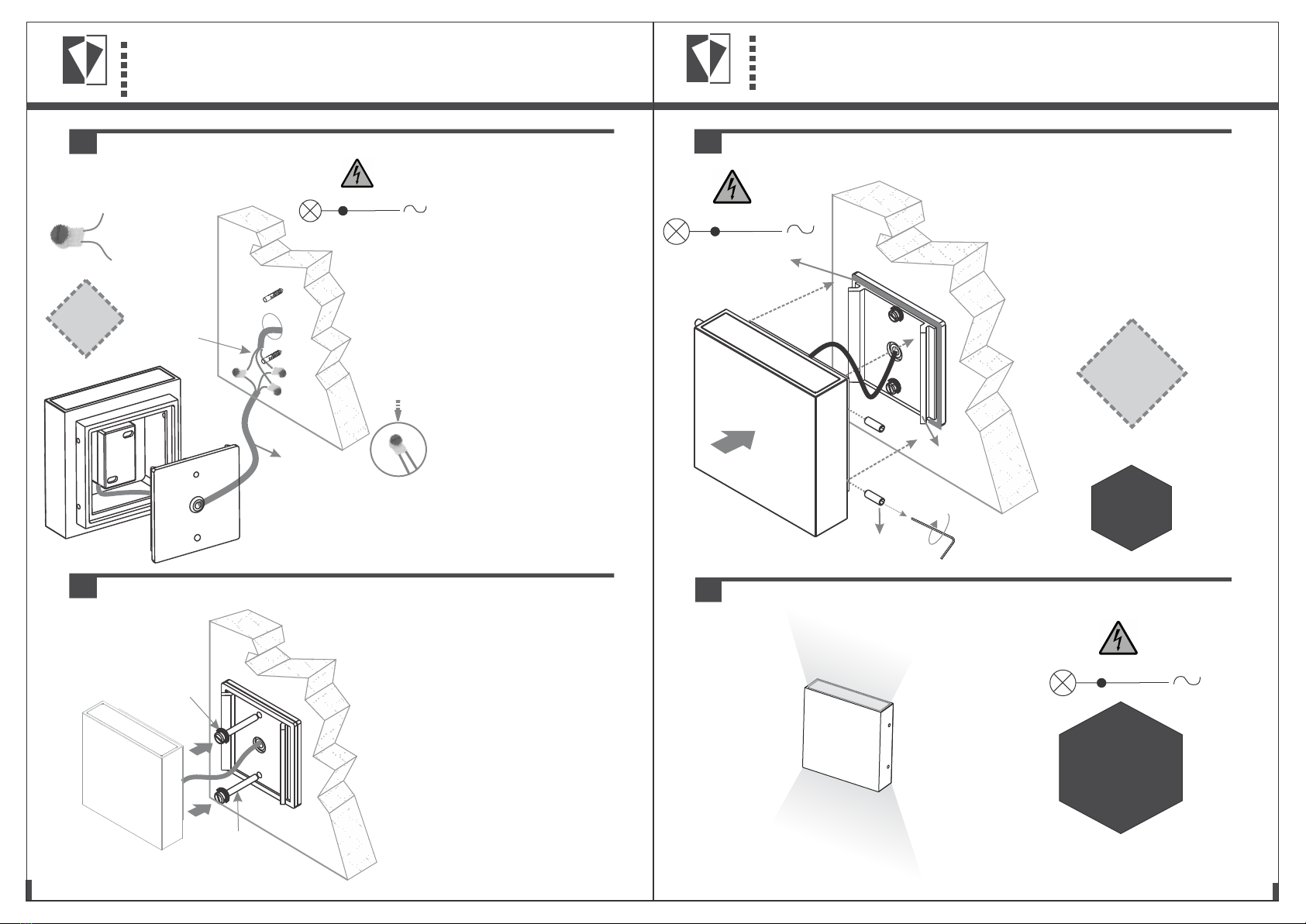
6. Switch on power supply.
ELECTRICAL CONNECTION
MOUNTING
Replaceable
electrical
components
by end user
CLOSING THE LUMINAIRE
DO NOT PLUG
(CONNECT) WHEN
LIVE AS IT WILL CAUSE
DAMAGE TO THE
LUMINAIRE.
(L) Brown/
(N) Blue/
Main supply
Light source
(E) Green/yellow
(L) Brown/
(N) Blue/
(E) Green/yellow
C
B
Strip the cable
before connecting
Press down to release
the gel resin, to retain the
IP rating once the cables
are securely fastened
into the connector.
Connector: 3M - J000788
x3 per bulkhead
DO NOT PLUG
(CONNECT) WHEN
LIVE AS IT WILL CAUSE
DAMAGE TO THE
LUMINAIRE.
Supplied electrical
cable tail
Connect the electrical cable from
the potted control gear to the
m a i n s u p p l y u s i n g t h e g e l
connectors (supplied).
B. Strip the main power supply
cable (Live, neutral and earth),
before connecting. Separately
connect the Live, Neutral and
Earth from the mains power supply
to the electrical cable tail supplied
o n t h e f i t t i n g u s i n g 3 g e l
connectors (Connector: 3M -
J000788) to maintain the IP rating.
C. Insert the two corresponding
c a bl e s c om p le te l y i n to t h e
connectors. Push the button on the
c o n n e c t o r ( i n d i c a t e d i n
red/orange) to release the gel
resin once the electrical cables
are secure.
Once complete, neatly place the
gel connectors into the wall,
ensuring that the cables are
secure.
3. Feed the electrical cable
through the cable grommet on the
back mounting plate.
Wall screw
Rubber
washer
Ensure there are rubber washers on
the wall screws to maintain the IP
rating of the fitting.
4. Fasten the back mounting plate
to the wall.
Ensure there is no trapped or
pinched electrical insulation when
mounting the back wall plate to the
wall.
Back plate
Gasket Ensure there is no trapped or
pinched electrical insulation.
Ensure the gasket is securely in
place and fasten the fitting to the
back mounting plate with the 4x M5
stainless steel grub screws.
5. Test the fitting before mounting.
M5 Grub screws
x4
Replaceable
electrical
components
by end user