manuals.online logo
Brands
  1. Home
  2. •
  3. Brands
  4. •
  5. Regent Lighting Solutions
  6. •
  7. Lighting Equipment
  8. •
  9. Regent Lighting Solutions Longo User manual

Regent Lighting Solutions Longo User manual

1
2
www.regentlight.co.za
INSTALLATION INSTRUCTIONS
ALL CONNECTIONS TO BE CARRIED OUT BY A QUALIFIED ELECTRICIAN
1
PLEASE READ CAREFULLY BEFORE STARTING INSTALLATION.
Regent Lighting reserves the right to change specifications modify designs and discontinue items without incurring obligation and
whilst every effort is made to ensure that descriptions, specifications and other information in this catalogue are correct, no
warranty is given in respect thereof and the company shall not be liable for any error therein.
WARNING: TO AVOID FIRE, SHOCK OR DEATH
TURN OFF POWER AT CIRCUIT BREAKER OR FUSE AND TEST THAT THE POWER IS OFF BEFORE WIRING
ALL LUMINAIRES SUPPLIED AND TO BE INSTALLED ABOVE AND BELOW 5 METERS ARE IN COMPLIANCE WITH SANS
60598 SECTION 3.5.6 ACCORDING TO THE MANUFACTURER GUARANTEE AND WARRANTY
Electrical products can cause death, injury, or damage to property. Installation of this product
must be carried out by a qualified electrician, in compliance with SANS 10142 or corresponding
regulations of the country of installation. On completion of installation, the Certificate of
Compliance must be updated.
WARNING
Electronic Control Device
WARNING
3 - 13 MAIN REEF SERVICE ROAD, CORNER
SPRINGBOK AND MAIN REEF ROAD, INDUSTRIA,
JOHANNESBURG. SOUTH AFRICA.
TEL : +27 11 474 0171
www.regentlight.co.za
RE GENT L I GHT ING A D IVIS ION
OF WA HL IND USTR IES.
Save These Instructions for Future Reference
ELECTRIC SHOCK
HAZARD
This equipment is to be
serviced by trained
personnel only.
ELECTRIC SHOCK
HAZARD
This equipment is to be
serviced by trained
personnel only.
Longo
DO NOT CONNECT THE FITTING LIVE
March 2018
For non replacable lightsources:
The light source of this luminaire is not replaceable; when the
light source reaches its end of life the whole luminaire shall be replaced
92MM
Product installed finished
with conduit drainage
FFL / Tiled Surface
Grout
Concrete
Drain
Product installed finished
with gravel drainage
Requirements:
Be sure the electricity to the system you are working on is isolated.
If the main supply power (live) is on, it will cause damage to the luminaire.
1. Select required position.
Create a cavity with drainage for fitting in the ground/paving at the required position.
The total height of the product is 92mm and SHOULD be level with the FINISHED floor level
- FFL (the tiled surface).
*NB: GRAVEL FOR DRAINAGE - Lay at least 150mm of gravel beneath the well of the cavity
and check drainage efficiency.
Ensure there is a drain under the gravel when installing the fitting into paving or cement.
92MM
FFL / Tiled Surface
Grout
Concrete
Gravel
DO NOT PLUG
(CONNECT) WHEN
LIVE AS IT WILL CAUSE
DAMAGE TO THE
LUMINAIRE.
9
9. Place the fitting into the aluminium extrusion.
Connect to main supply using the electrical tail
supplied from the fitting.
Ensure the fitting is secure in the aluminium
extrusion.
Fitting
Electrical
tail
Mains to
Luminaire
Earth Loop
Green/Yellow
Switch
Live Red
Neutral loop
Black or Blue
(L) Brown
(E) Green/Yellow
(N) Blue
DO NOT PLUG
(CONNECT) WHEN
LIVE AS IT WILL CAUSE
DAMAGE TO THE
LUMINAIRE.
www.regentlight.co.za
7
8
This product should be installed by a competent person i.e. Qualified electrician.
This product requires a constant stable electrical supply 220V - 240V VAC 50Hz - alternating current.
The product must be regularly maintained, including the replacement of lamps/LED timeously.
This product could be HAZARDOUS if not used correctly, it could cause electric shock, serious bodily harm or death.
This product is not a toy, please keep away from children.
This product may contain small parts that can be swallowed.
Use only the correct light bulbs/LED as stipulated on the carton for the product.
Any modifications of this product after supply will result in the guarantee being void.
Spare parts may become unavailable over time.Items can vary slightly from the picture on the carton
Coastal humidity can affect the longevity of the light fitting over time.
Be sure to follow the steps in the order given.
Read instructions carefully.
Important Safety Instructions
2 3
Drain Conduit
Drain Conduit locator
Casting
polystyrene
plug
Protrude the
drain conduit
through the
polystyrene
3. Place the casting polystyrene
plug with the drain conduit in position on the
slab before casting the concrete. Ensure the
polystyrene plug is at the correct level on the
positioning wedges.
Cast the concrete / surface bed.
2. Place the Drain conduit locator under the
casting polystyrene plug before placing it in
the cavity. Protrude the drain conduit
through the polystyrene.
2 3
92MM
Casting
polystyrene
plug
F.F.L
SLAB
Surface bed/
concrete
Positioning
wedge
Drain conduit
STEP 2
2 5
Polystyrene Casting plug
Surface
bed
Conduit for wiring
to main supply
4. Ensure there is a conduit in the cavity to
the main supply. All fittings are supplied with
an electrical tail.
4
5. A. Once the concrete has set, remove the
polystyrene casting plug from the cavity,
indicated in A & B.
Surface bed
without polystyrene
casting plug
Drainage
B
Casting
polystyrene
plug
Concrete
surface
bed
A
Endcap
Fisher plate
for continuous lengths
26 7
6. Prepare the aluminium extrusion by
fastening the end caps and/or fischer plate
(for continuous lengths) to the extrusion.
Ensure the extrusion has drainage holes.
Ensure the end caps and fisher plates are
securely fastened.
Aluminium
extrusion
FFL
TRIM
CONDUIT
TRIM
CONDUIT
7. Align and place the assembled aluminium
extrusion into the cast cavity over the drainage
conduit, ensure the extrusion protrudes from the
surface bed to the FFL.
Ensure the Aluminium extrusion is securely placed in
the cavity. Trim the protruding conduit to the base
of the extrusion.
28
Tiling plug
A
Tiling finished floor
Grout
Tiling plug
B
Tiling plug
C
A: Insert tiling polystyrene plug
into the extrusion before
grouting and tiling up to the
finished floor level.
B: Grout around the extrusion
and tile up to the aluminium
extrusion edge or FFL.
Ensure that no grouting gets
trapped into the aluminium
extrusion.
C: Remove the tiling
polystyrene plug from the
aluminium extrusion.
Ensure there is no grout in the
extrusion.
STEP 9 continued on the next
page...
Other Regent Lighting Solutions Lighting Equipment manuals

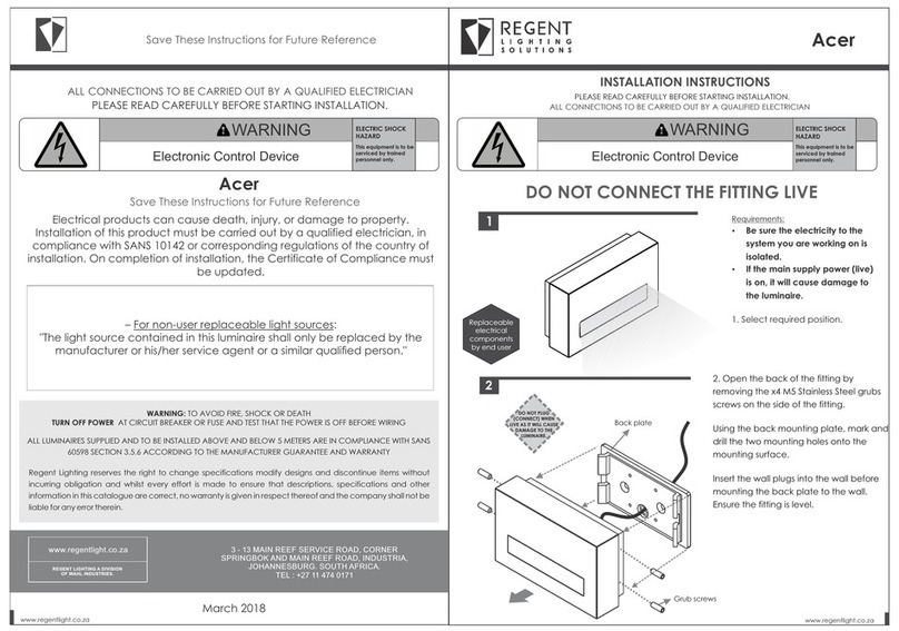
Regent Lighting Solutions Acer User manual

Regent Lighting Solutions

Regent Lighting Solutions Acer User manual

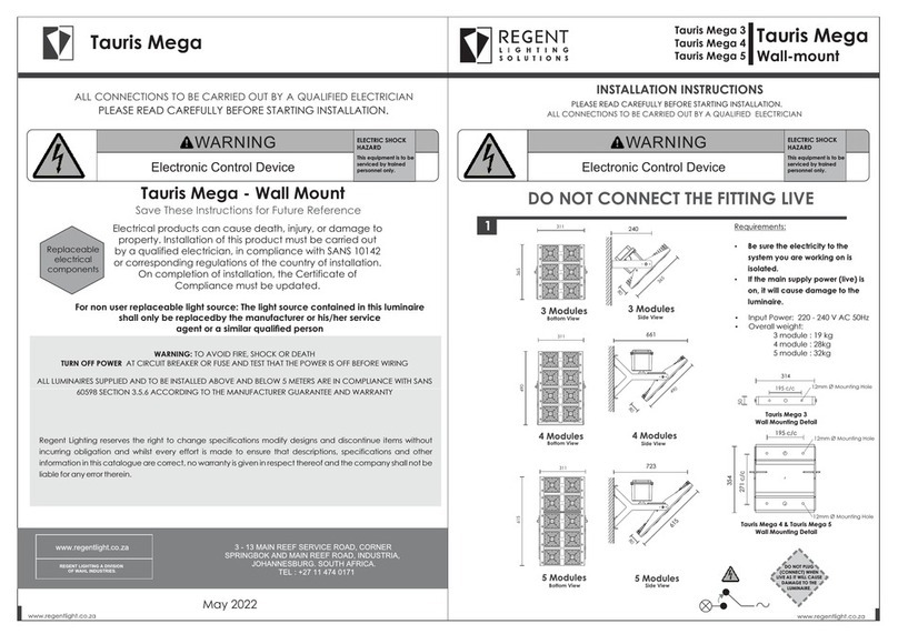
Regent Lighting Solutions Tauris Mega 3 User manual

Regent Lighting Solutions

Regent Lighting Solutions Tauris Mega 3 User manual

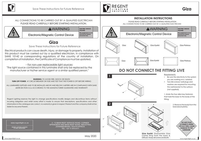
Regent Lighting Solutions Giza User manual

Regent Lighting Solutions

Regent Lighting Solutions Giza User manual

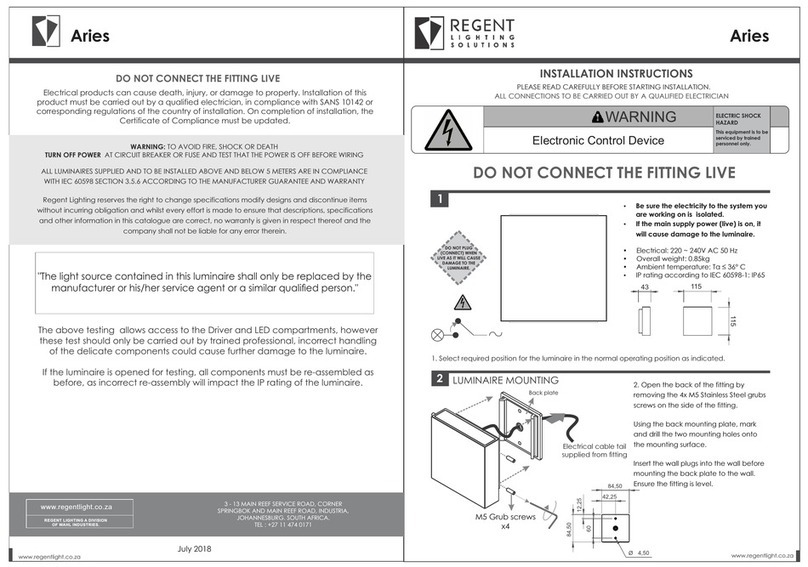
Regent Lighting Solutions Aries User manual

Regent Lighting Solutions

Regent Lighting Solutions Aries User manual

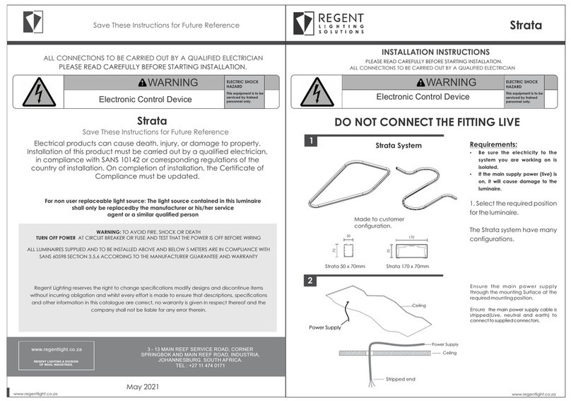
Regent Lighting Solutions Strata User manual

Regent Lighting Solutions

Regent Lighting Solutions Strata User manual

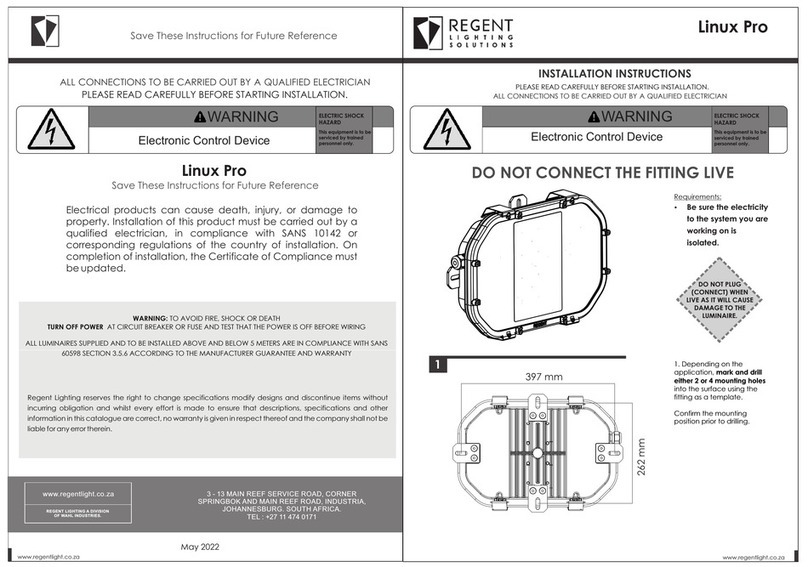
Regent Lighting Solutions Linux Pro User manual

Regent Lighting Solutions

Regent Lighting Solutions Linux Pro User manual

Popular Lighting Equipment manuals by other brands

Harvia SASF06 Instructions for installation

Harvia

Harvia SASF06 Instructions for installation

Aura Light Morus installation manual

Aura Light

Aura Light Morus installation manual

BOT LIGHTING VIGO-E27 Use and installation  manual

BOT LIGHTING

BOT LIGHTING VIGO-E27 Use and installation manual

Steren LAM-010 user manual

Steren

Steren LAM-010 user manual

American DJ Gobo Splash User instruction

American DJ

American DJ Gobo Splash User instruction

marset Chispa Assembly instructions

marset

marset Chispa Assembly instructions

Jinbei KE Series manual

Jinbei

Jinbei KE Series manual

Beamz 69 LEDs Revo 12 Burst 153.433 user manual

Beamz

Beamz 69 LEDs Revo 12 Burst 153.433 user manual

DTS DONUT 6 user manual

DTS

DTS DONUT 6 user manual

Philips TT155 Mounting instruction

Philips

Philips TT155 Mounting instruction

Autopilot ChlorSync CS30 Owners & installation manual

Autopilot

Autopilot ChlorSync CS30 Owners & installation manual

Mr Maria MR LED8 user manual

Mr Maria

Mr Maria MR LED8 user manual

TSL ROI-E420 Series user manual

TSL

TSL ROI-E420 Series user manual

IMMAX NEO LITE user manual

IMMAX

IMMAX NEO LITE user manual

BASEWEST 700 Series operating & maintenance manual

BASEWEST

BASEWEST 700 Series operating & maintenance manual

HOMBLI Smart Pathway Light manual

HOMBLI

HOMBLI Smart Pathway Light manual

Adaptive Micro Systems Beta Brite Programming manual

Adaptive Micro Systems

Adaptive Micro Systems Beta Brite Programming manual

Magicshine MAGENE SEEMEE 508 user manual

Magicshine

Magicshine MAGENE SEEMEE 508 user manual

manuals.online logo
manuals.online logoBrands
  • About & Mission
  • Contact us
  • Privacy Policy
  • Terms and Conditions

Copyright 2025 Manuals.Online. All Rights Reserved.