www.regentlight.co.za
www.regentlight.co.za
3
4
5
7
8
6
7
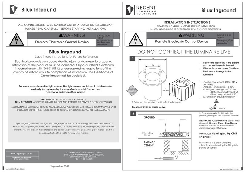
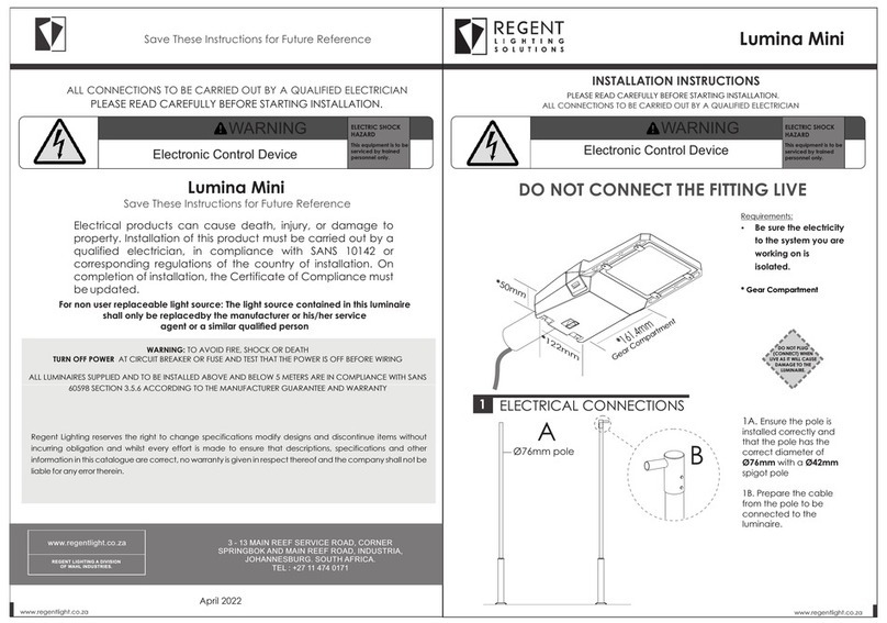
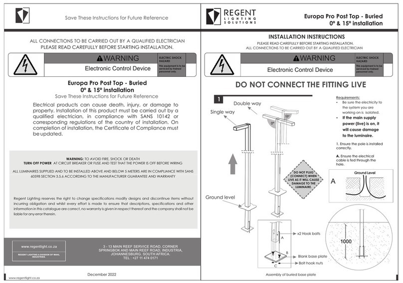
This product should be installed by a competent person i.e. Qualified electrician.
This product requires a constant stable electrical supply 220V - 240V VAC 50Hz - alternating current.
The product must be regularly maintained, including the replacement of lamps/LED timeously.
This product could be HAZARDOUS if not used correctly, it could cause electric shock, serious bodily harm or death.
This product is not a toy, please keep away from children.
This product may contain small parts that can be swallowed.
Use only the correct light bulbs/LED as stipulated on the carton for the product.
Any modifications of this product after supply will result in the guarantee being void.
Spare parts may become unavailable over time.Items can vary slightly from the picture on the carton
Coastal humidity can affect the longevity of the light fitting over time.
Be sure to follow the steps in the order given.
Read instructions carefully.
Important Safety Instructions
8
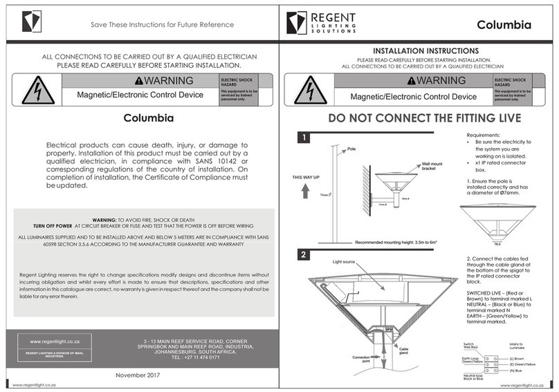
Mains to
Luminaire
Earth Loop
Green/Yellow
Switch
Live Red
Neutral loop
Black or Blue
(L) Brown
(E) Green/Yellow
(N) Blue
The above testing allows access to the Driver and LED compartments, however
these test should only be carried out by trained professional, incorrect handling of
the delicate components could cause further damage to the luminaire. If the
luminaire is opened for testing, all components must be re-assembled as before,
as incorrect re-assembly will impact the IP rating of the luminaire.
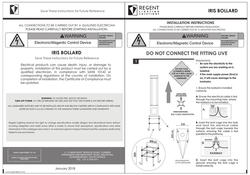
5B. Inside the tting
are x2 M8 screws,
using an allen key to
tighten the tting
onto the pole.
5. Remove the back
end cap and the
gasket of the tting
by undoing one
countersunk screw in
the centre of the end
cap. When undoing
hold onto the end
cap as it will fall to the
ground
When reassembling the
tting insure that the
gaskets are correctly
installed
Note not to pinch the
gaskets when installing
the diffuser.
4A. push the excess
wire from the
connection down
into the pole.
4B. Align the tting
hole with the
reduction rod on the
pole and slide over
the pole.
3B. Test the tting to
make sure all
connections are
correct.
3A. Connect the
tting power lead to
the pole power lead
using the male
female connector.
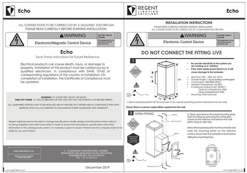
DO NOT PLUG
(CONNECT) WHEN
LIVE AS IT WILL CAUSE
DAMAGE TO THE
LUMINAIRE.
Replaceable
electrical
components
Replaceable
electrical
components
LED gear tray
Access
door
-First check circuit
breaker before
opening tting
In the event of a failure.
-To begin fault nding,
loosen the x2 M4
screws to open the
access door.
-Secure access door
when removing screws
so that it doesn't fall
and break
- To remove the LED
gear tray, undo the
two M6 sockets found
inside of the tting.
Once loss slide the
gear tray by pull on the
end cap
Click* *
End cap
Gasket
End cap
Gasket
Grab screws
Ensure not to pinch or
damage the gasket
when placing the end
cap over it.
Followed by the end
cap.
6. Replace the gasket
back into the tting.
Hold the end cap in
place so it don't fall off,
screw on the counter
sunk screw back on.
M4 screws
ZFIC001 PIAZZA
CLASS I/II IP00
LOT 00000
230V 50Hz
LIGHTING
REGENT
LED/W/K
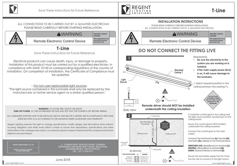
Remote driver should NOT be installed
underneath the ceiling insulation.
INSTALLATION INSTRUCTIONS
3. Fix the back mounting bracket to the wall with the screws/wall
plugs provided.
2. Connect the Switched Live (S/A), Neutral (N) and Earth (E)
cable(s) to the terminal block.
Be sure the electricity to the system you are working on is
isolated.
8. Replace the lid.
EARTH – (Green/Yellow) to terminal marked E.
1. Select the required position for the luminaire.
SWITCHED LIVE – (Red or Brown) to terminal marked L
4. Ensure that there are no exposed conductors, loose strands or
trapped insulation.
5. To install or change the lamp, unscrew and remove the lid from
the main body, taking care of any loose parts which may fall.
Ensure the new lamp is the correct wattage and is located in the
lamp holder.
NEUTRAL – (Black or Blue) to terminal marked N
9. Switch on the power supply.
Wall Bracket Installation Instructions
Be sure the electricity to the system you are working on is
isolated.
1. Select the required position for the luminaire.
2. Remove the back mounting plate from the fitting.
3. Connect the Switched Live (S/A), Neutral (N) and Earth (E)
cable(s) to the terminal block.
NEUTRAL – (Black or Blue) to terminal marked N
4. Fix the back mounting plate to the wall with the screws/wall plugs
provided.
SWITCHED LIVE – (Red or Brown) to terminal marked L
7. To install or change the lamp, remove the main bodycover,
taking care of any loose parts which may fall. Ensure the new lamp
is the correct wattage and is located in the lamp holder.
5. Ensure that there are no exposed conductors, loose strands or
trapped insulation.
9. Switch on the power supply.
6. Replace the main body of the luminaire, ensuring the cables are
not trapped between the base mounting bracket and the main
base.
8. Replace the lamp cover.
EARTH – (Green/Yellow) to terminal marked E.
Bulkhead Installation Instructions
SWITCHED LIVE – (Red or Brown) to terminal marked L
EARTH – (Green/Yellow) to terminal marked E.
3. Fix the base mounting to the required position with the
screws/wall plugs provided.
Be sure the electricity to the system you are working on is isolated.
1. Select the required position for the luminaire.
2. Connect the Switched Live (S/A), Neutral (N) and Earth (E)
cable(s) to the terminal block.
NEUTRAL – (Black or Blue) to terminal marked N
6. Replace the lid.
7. Switch on the power supply.
5. To install or change the lamp, unscrew and remove the lid from
the main body, taking care of any loose parts which may fall.
Ensure the new lamp is the correct wattage and is located in the
lamp holder.
4. Ensure that there are no exposed conductors, loose strands or
trapped insulation.
7. Switch on the power supply.
6. Replace the lid.
5. To install or change the lamp, unscrew and remove the lid from
the main body, taking care of any loose parts which may fall.
Ensure the new lamp is the correct wattage and is located in the
lamp holder.
1. Select the required position for the luminaire.
SWITCHED LIVE – (Red or Brown) to terminal marked L
NEUTRAL – (Black or Blue) to terminal marked N
EARTH – (Green/Yellow) to terminal marked E.
2. Connect the Switched Live (S/A), Neutral (N) and Earth (E)
cable(s) to the terminal block.
3. Fix the ceiling mounting bracket to the ceiling with the
screws/wall plugs provided.
Be sure the electricity to the system you are working on is isolated
4. Ensure that there are no exposed conductors, loose strands or
trapped insulation.
Pedestal Installation Instructions Ceiling Installation Instructions
Post Top Installation Instructions
5. To install or change the lamp, unscrew and remove the lid from
the main body, taking care of any loose parts which may fall.
Ensure the new lamp is the correct wattage and is located in the
lamp holder.
EARTH – (Green/Yellow) to terminal marked E.
4. Ensure that there are no exposed conductors, loose strands or
trapped insulation.
2. Connect the Switched Live (S/A), Neutral (N) and Earth (E)
cable(s) to the terminal block.
3. Place the post top on the pole and tighten the grub screw.
NEUTRAL – (Black or Blue) to terminal marked N
Be sure the electricity to the system you are working on is isolated
7. Switch on the power supply.
SWITCHED LIVE – (Red or Brown) to terminal marked L
6. Replace the lid.
1. Ensure the pole is installed correctly.
ZFIC001 PIAZZA
CLASS 1 IP 65
LOT 43608
LED 9W 4K
230V 50Hz
REGENT
LIGHTING
ZFIC001 PIAZZA
CLASS 1 IP 65
LOT 43608
REGENT
230V 50Hz
LED 9W 4K
LIGHTING
ZFIC001 PIAZZA
CLASS I/II IP00
LOT 00000
HPS/MH/MV/
CFL/LFL/W
LIGHTING
230V 50Hz
REGENT
WARNING
Electronic/Magnetic Control Device
ELECTRIC SHOCK
HAZARD
This equipment is to be
serviced by trained
personnel only.
End cap
M6 socket
