manuals.online logo
Brands
  1. Home
  2. •
  3. Brands
  4. •
  5. Reliable
  6. •
  7. Irrigation System
  8. •
  9. Reliable KFR-CCS User manual

Reliable KFR-CCS User manual

Features
• cULus Listed for areas of coverage up to 256 square feet
• Sprinkler may be installed on the same branch line that
supplies sprinklers below ceiling
• Nominal K-factor of 5.6 (80 metric)
• Fusible link operating element
• Quick response 212°F (100°C) fusible link operating
element
• Standard brass finish
Product Description
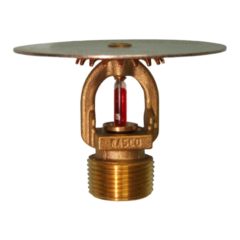
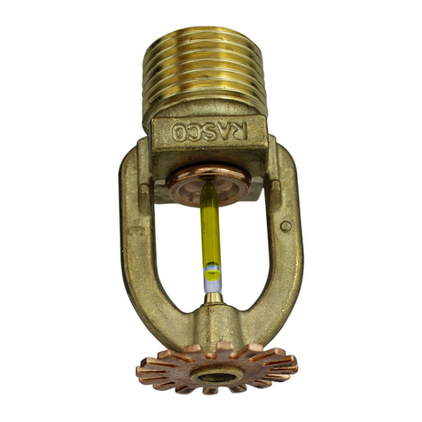
Reliable’s Model KFR-CCS Combustible Concealed Space
Sprinkler is a quick response, upright, special sprinkler
designed to provide protection of specific light hazard
combustible and noncombustible concealed spaces requiring
sprinkler protection. The KFR-CCS sprinkler is specifically
listed for the protection of shallow combustible concealed
spaces described in NFPA 13.
The Model KFR-CCS Sprinkler utilizes a fast response
solder-link fusible element that has demonstrated response
times in laboratory tests which are five to ten times faster
than standard response sprinklers. This feature enables the
sprinkler to apply water to a fire much faster than standard
response sprinklers of the same temperature rating.
Application
The Model KFR-CCS sprinkler is specifically listed for use
in horizontal combustible concealed spaces with a slope
not exceeding 2:12 with combustible wood truss, wood joist
construction, or bar joist construction having a combustible
upper surface and where the depth of the space is less than
36” (914 mm) from deck to deck, from deck to ceiling, or with
double wood joist construction with a maximum of 36” (914
mm) between the top of the bottom joist and the bottom of the
upper joist. NFPA 13 permits the use of the Model KFR-CCS
sprinkler (a) where the space is less than 12” (305 mm) from
deck to deck or deck to ceiling, and/or (b) where a portion of
the protected space exceeds 36” (914 mm).
Installation
Model KFR-CCS Sprinklers are to be installed in the upright
position with their frames arms parallel to the pipe (Refer
to Figs. 4 through 9). When installing the Model KFR-CCS
sprinkler use only the Reliable Model W2 installation wrench.
Usage of any other type of installation wrench may damage
the sprinkler and will immediately void the manufacture’s
warranty.
www.reliablesprinkler.com
cULus Listed
Model KFR-CCS Combustible Concealed
Space Sprinkler
Bulletin 044 June 2020
Note: A leak tight ½” NPT (R1/2) sprinkler joint can be
obtained with an installation torque of approximately 8 -18
ft-lbs (10.8 – 24.4 N-m). Do not tighten sprinklers over these
recommended limits. Doing so may cause leakage and/or
premature operation.
Maintenance
Model KFR-CCS Sprinklers should be inspected and
maintained in accordance with the applicable version of NFPA
25. Do not clean sprinklers with soap and water, ammonia or
any other cleaning fluids. Remove dust by using compressed
air or by vacuuming, provided equipment does not touch the
sprinkler. Replace any sprinkler which has been painted (other
than factory applied) or damaged in any way. A stock of spare
sprinklers should be maintained to allow quick replacement
of damaged or operated sprinklers. Prior to installation,
sprinklers should be maintained in the original cartons and
packaging to minimize the potential for damage to sprinklers
that would cause improper operation or non-operation.
Guarantee
For Reliable Automatic Sprinkler Co., Inc. guarantee, terms,
and conditions, visit www.reliablesprinkler.com.
Ordering Information
Specify: Model KFR-CCS Sprinkler
Model W2 Wrench
Model KFR-CCS Components and Installation Dimensions Figure 1
Technical Specifications
Style: Upright
Threads: 1/2” NPT or ISO7-1R1/2
Nominal K-Factor: 5.6 (80 metric)
Max. Working Pressure: 175 psi (12 bar)
Material Specifications
Thermal Sensor: Nickel Alloy
Sprinkler Frame: Brass Alloy
Button: Copper Alloy
Sealing Assembly: Nickel Alloy with PTFE
Load Screw: Bronze Alloy
Deflector: Bronze Alloy
Finish
Standard Brass
Temperature Ratings
212°F (100°C)
Sensitivity
Fast Response
Sprinkler Wrench
Model W2
Approvals
cULus Listed
Model KFR-CCS Combustible Concealed Space Upright Sprinkler SIN RA4454
Bulletin 044
June 2020
Page 2 of 9
www.reliablesprinkler.com
Model KFR-CCS General Application Criteria
Minimum Distance (Spacing) Between Sprinklers
6’ (1.83 m)
Note: This minimum spacing does not apply to any additional sprinklers that are required for protection of CPVC piping that is
offset over an obstruction (refer to figures 4 and 5).
Maximum Distance (Spacing) Between Sprinklers
14’ (4.27 m) for solid wood and composite wood joist construction. For wood truss or bar joist construction, 14’ (4.27 m) for
concealed spaces that are less than 18” (457 mm) in depth; 16’ (4.88 m) for concealed spaces that are 18” (457 mm) or more in
depth.
Maximum Coverage Area Per Sprinkler
196 ft2 (18.2 m2) for solid wood or composite wood joist construction. For wood truss or bar joist construction, 196 ft2 (18.2 m2)
for concealed spaces that are less than 18” (457 mm) in depth; 256 ft2 (23.8 m2) for concealed spaces that are 18” (457 mm) or
more in depth.
Note: Sprinkler spacing, and therefore coverage area, is determined by the depth of the concealed space. When transitions
occur in the concealed space, the sprinklers may immediately be spaced at the largest approved coverage area per the above
listings for the concealed space depth (refer to Fig. 2).
Obstruction Rules
All obstruction criteria per the applicable version of the NFPA 13 apply unless modified by this bulletin (refer to Fig. 3). The KFR-
CCS is classified as an Extended Coverage Upright Spray Sprinkler where the maximum coverage area per sprinkler exceeds
225 ft2 (20.9 m2). The KFR-CCS is classified as a Standard Upright Spray Sprinkler where the maximum coverage area per
sprinkler is 225 ft2(20.9 m2) or less.
Figure 2
Model KFR-CCS Sprinkler Spacing at Change in Concealed Space Depth
Bulletin 044
June 2020
Page 3 of 9
www.reliablesprinkler.com
Figure 3
Model KFR-CCS Specific Application Obstruction Criteria
Bulletin 044
June 2020
Page 4 of 9
www.reliablesprinkler.com
Bulletin 044
June 2020
Page 5 of 9
www.reliablesprinkler.com
When used with CPVC piping, the Model KFR-CCS Sprinkler
is specifically listed to provide protection of combustible con-
cealed spaces where the construction methods consist of:
1. Wood trusses or wood bar joist (Refer to Fig. 4)
2. Noncombustible insulation-filled solid wood or composite
wood joists*(Refer to Fig. 5)
*Note: In order to be considered “noncombustible insula-
tion-filled, solid wood or composite wood joists” construction,
the insulation (including insulation provided with a combusti-
ble vapor barrier), must completely fill the pockets between
the joists to the bottom of the joists. Insulation installed above
the elevation of Model KFR-CCS sprinklers in wood truss, solid
wood joist or composite wood joist must be secured into place
with metal wire netting. The metal wire netting is intended to
hold the insulation in place should the insulation become wet
by the operation of Model KFR-CCS Sprinklers in the event of
a fire.
In order to use the CPVC pipe and fittings, the horizontal
runs of pipe must be a maximum of 6 in. (152 mm) above the
ceiling or noncombustible ceiling insulation, or 1/3 the depth
of concealed space (as measured from the top surface of the
ceiling to the bottom of the deck above), whichever is smaller
(Refer to Figs. 4 & 5).
The CPVC piping can be used to supply the Model KFR-CCS
Sprinklers as well as sprinklers installed below the ceiling.
Unless modified by this technical data sheet, all guidelines
provided by the CPVC pipe and fitting manufacturer must be
followed.
When using 1 in. (DN25) or larger pipe, a hanger must be
located at the truss nearest a sprig for purposes of restraint.
If using 3/4 in. (DN19) piping, all sprigs over 12 in. (305 mm)
must be laterally braced using methods described in the
NFPA standards. Where the CPVC must be offset up and over
an obstruction and the pipe exceeds the allowed horizontal
positioning requirements specified above as well as shown
in Figs. 4 and 5, additional Model KFR-CCS Sprinklers are to
be installed to protect the CPVC products. A minimum lateral
distance of 18 in. (457 mm) must be maintained between the
CPVC pipe and heat pumps, fan motors, and heat lamps.
Concealed Space Area
The area of the concealed space is not limited; however, for
both Figs. 4 and Fig. 5 where CPVC pipe is being utilized,
draft-curtains or full height walls must be provided at 1,000 ft2
(93 m2) maximum areas. This draft curtain shall be at least 1/3
the depth of the concealed space or 8 in. (203 mm), whichev-
er is greater, and be constructed using a material that will not
allow heat to escape through or above the draft curtain.
System Type
Light hazard, wet pipe system.
Minimum Distance Away From Face of Wood Truss or Top
Chord of Bar Joist
4.5 in. (114 mm) (Refer to Fig. 3)
Deflector Position
At or below the bottom of the top chord; 1.5 in. (38 mm)
minimum to 4 in. (102mm) maximum below upper deck (or
insulation if present) for wood truss construction or wood bar
joist construction (Fig. 4).
1.5 in. (38 mm) minimum to 4 in. (102mm) maximum below
bottom of insulation for noncombustible insulation-filled solid
or composite joist construction (Fig. 5).
Hydraulic Design Area
Calculate all sprinklers within the draft curtain area, up
to the 1,000 ft2(93 m2) maximum draft curtain area.
Note: Additional sprinklers that are required for protection of
CPVC piping that is offset over an obstruction do not need to
be included in the remote area.
Required Density
0.10 gpm/ft2(4.08 Lpm/m2)
Minimum Operating Pressure
7 psi (0.48 bar)
Model KFR-CCS Specific Application Criteria for CPVC Pipe Sprinkler Systems
Figure 4
Model KFR-CCS CPVC Pipe
Bulletin 044
June 2020
Page 6 of 9
www.reliablesprinkler.com
Figure 5
Model KFR-CCS CPVC Pipe
When used with steel piping, the Model KFR-CCS Sprinkler
is specifically listed to provide protection of combustible
concealed areas where the construction methods consist of:
1. Wood trusses or wood bar joists (Refer to Fig. 6)
2. Solid wood joist construction where the upper ceiling
joists may have a maximum depth of 12 in. (305 mm).
(Refer to Fig. 7).
3. Noncombustible insulation-filled, solid wood or composite
wood joists*(Refer to Fig. 8)
4. Obstructed wood trusses; top chord more than 4” deep
(Refer to Fig. 9).
*Note: In order to be considered “noncombustible insulation-
filled, solid wood or composite wood joists” construction, the
insulation (including insulation provided with a combustible
vapor barrier), must completely fill the pockets between the
joists to the bottom of the joists. Insulation installed above the
elevation of Model KFR-CCS sprinklers in wood truss, solid
wood joist or composite wood joist must be secured into place
with metal wire netting. The metal wire netting is intended to
hold the insulation in place should the insulation become wet
by the operation of Model KFR-CCS Sprinklers in the event of
a fire.
Concealed Space Area
The area of the concealed space is not limited; however,
for wood truss construction or concealed spaces of
noncombustible bar joist construction (Refer to Fig. 6) draft-
curtains or full height walls must be provided at 1,000 ft2 (93
m2) areas. The draft curtain shall be at least 1/3 the depth of
the concealed space or 8 in. (203 mm), whichever is greater,
and be constructed using a material that will not allow heat to
escape through or above the draft curtain.
For solid wood joist construction (Refer to Fig. 7) and
obstructed wood truss construction (Refer to Fig. 8), blocking
must be provided in each joist or top chord channel at
maximum 32 ft. (9.75 m) intervals. This blocking shall be
installed to the full depth of the joist or top chord and be
installed so as to not allow heat to escape through or above
the blocking. The blocking must be constructed using a
noncombustible material or be of the same material as the
joist or truss member. Draft curtains must be protrude below
the joist a minimum of 6 in. (152 mm) or 1/3 the space,
whichever is greatest and run parallel with the joist spaced at
31 ft. (9.45 m) width maximum to limit the area to a maximum
of 1,000 ft2(93 m2). The draft curtain may be constructed of ¼
in. (6.4 m) plywood to prevent heat from escaping beyond the
area.
For noncombustible insulation-filled, solid wood joist or
composite wood joist construction (Refer to Fig. 9), the
requirement for draft curtains or blocking does not apply.
System Type
Light hazard, wet or dry pipe system.
Deflector Position
At or below the bottom of the top chord; 1.5 in. (38 mm)
minimum to 4 in. (102mm) maximum below upper deck (or
insulation if present) for wood truss construction or wood bar
joist construction (Fig. 6).
1.5 in. (38 mm) minimum to 2 in. (51 mm) maximum below the
bottom of the top chord for spaces constructed of obstructed
wood trusses (Fig. 8).
1.5 in. (38 mm) minimum to 2 in. (51 mm) maximum below the
bottom of the upper joist for concealed spaces constructed of
exposed solid wood joists (Fig 7).
1.5 in. (38 mm) minimum to 4 in. (102mm) maximum below
bottom of insulation for noncombustible insulation-filled solid
or composite joist construction (Fig. 9).
Minimum Distance Away From Face of Wood Truss or Top
Chord of Bar Joist
4.5 in. (114 mm) (Refer to Fig. 4)
Hydraulic Design Area
For wood truss construction (Fig. 6), solid wood joist
construction (Fig. 7), or obstructed wood truss construction
(Fig. 8), calculate all sprinklers within the draft curtain area,
up to the 1,000 ft2(93 m2) maximum draft curtain area for both
wet and dry pipe systems.
For noncombustible insulation-filled solid wood joist or
composite wood joist construction (Fig. 9) where draft curtains
are not required, calculate per the requirements of NFPA 13.
Required Density
0.10 gpm/ft2(4.08 Lpm/m2)
Minimum Operating Pressure
7 psi (0.48 bar)
Bulletin 044
June 2020
Page 7 of 9
www.reliablesprinkler.com
Model KFR-CCS Specific Application Criteria for Steel Pipe Systems
Figure 6
Model KFR-CCS Steel Pipe
Figure 7
Model KFR-CCS Steel Pipe
Bulletin 044
June 2020
Page 8 of 9
www.reliablesprinkler.com
P/N 9999970449
Figure 8
Model KFR-CCS Steel Pipe
Figure 9
Model KFR-CCS Steel Pipe
Bulletin 044
June 2020
Page 9 of 9
www.reliablesprinkler.com

Other manuals for KFR-CCS

1

Other Reliable Irrigation System manuals

Reliable JL-17 User guide

Reliable

Reliable JL-17 User guide

Reliable F1FR-SS Series Manual

Reliable

Reliable F1FR-SS Series Manual

Reliable F1FR Series Manual

Reliable

Reliable F1FR Series Manual

Reliable F1FR28 Series User manual

Reliable

Reliable F1FR28 Series User manual

Reliable F1-SS Series User manual

Reliable

Reliable F1-SS Series User manual

Reliable JL-17 User manual

Reliable

Reliable JL-17 User manual

Reliable F1FR User manual

Reliable

Reliable F1FR User manual

Reliable Sidewall Concealer SWC User manual

Reliable

Reliable Sidewall Concealer SWC User manual

Reliable F156 Series User manual

Reliable

Reliable F156 Series User manual

Reliable G5 Series User manual

Reliable

Reliable G5 Series User manual

Reliable RFC56 User manual

Reliable

Reliable RFC56 User manual

Reliable GL 112 User manual

Reliable

Reliable GL 112 User manual

Reliable F1FR-FS56 Manual

Reliable

Reliable F1FR-FS56 Manual

Reliable F1FR QREC Manual

Reliable

Reliable F1FR QREC Manual

Reliable F1FR 300 QREC Manual

Reliable

Reliable F1FR 300 QREC Manual

Reliable The Non-Ferrous Concealer F4FR-NF User manual

Reliable

Reliable The Non-Ferrous Concealer F4FR-NF User manual

Reliable F1-300 Manual

Reliable

Reliable F1-300 Manual

Reliable RFC56 User manual

Reliable

Reliable RFC56 User manual

Reliable KFR56 Series User manual

Reliable

Reliable KFR56 Series User manual

Reliable DDX PrePaK D Maintenance manual

Reliable

Reliable DDX PrePaK D Maintenance manual

Reliable DH80 User manual

Reliable

Reliable DH80 User manual

Reliable KFR-CCS User manual

Reliable

Reliable KFR-CCS User manual

Reliable G4 User manual

Reliable

Reliable G4 User manual

Reliable G Series User manual

Reliable

Reliable G Series User manual

Popular Irrigation System manuals by other brands

Rain Bird SST-1200s Operation manual

Rain Bird

Rain Bird SST-1200s Operation manual

Rain Bird 500 series Operation & maintenance manual

Rain Bird

Rain Bird 500 series Operation & maintenance manual

GEM G100 manual

GEM

GEM G100 manual

Tyco Fire Product Gem AQUARIUS F990 instruction manual

Tyco Fire Product

Tyco Fire Product Gem AQUARIUS F990 instruction manual

IrrigationCaddy IC-W1 quick start guide

IrrigationCaddy

IrrigationCaddy IC-W1 quick start guide

Tyco Fire Product Star SuperNova S126 instruction manual

Tyco Fire Product

Tyco Fire Product Star SuperNova S126 instruction manual

Nelso twig user guide

Nelso

Nelso twig user guide

Johnson Controls tyco TY-FRB Series manual

Johnson Controls

Johnson Controls tyco TY-FRB Series manual

Gardena AquaContour automatic 8133 operating instructions

Gardena

Gardena AquaContour automatic 8133 operating instructions

Tyco TY-B Series quick start guide

Tyco

Tyco TY-B Series quick start guide

NeilMed Hydro Pulse HP-100 User instructions

NeilMed

NeilMed Hydro Pulse HP-100 User instructions

Viking VK4921 Technical data

Viking

Viking VK4921 Technical data

Tyco Fire Product RAPID RESPONSE LFII Series instruction manual

Tyco Fire Product

Tyco Fire Product RAPID RESPONSE LFII Series instruction manual

Viking FREEDOM VK467 Technical data

Viking

Viking FREEDOM VK467 Technical data

Tyco Fire Product CENTRAL ESLO instruction manual

Tyco Fire Product

Tyco Fire Product CENTRAL ESLO instruction manual

Tyco DS-1 Series manual

Tyco

Tyco DS-1 Series manual

Eden 96214EDAMZ quick start guide

Eden

Eden 96214EDAMZ quick start guide

Tyco ESFR-17 manual

Tyco

Tyco ESFR-17 manual

manuals.online logo
manuals.online logoBrands
  • About & Mission
  • Contact us
  • Privacy Policy
  • Terms and Conditions

Copyright 2025 Manuals.Online. All Rights Reserved.