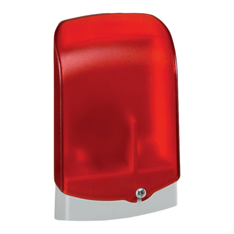
Resol AM1 User manual

Alarmmodul AM1
www.resol.de
Vielen Dank für den Kauf dieses RESOL-Gerätes.
Bitte lesen Sie diese Anleitung sorgfältig durch, um die Leistungsfähigkeit
dieses Gerätes optimal nutzen zu können.
Bitte bewahren Sie diese Anleitung sorgfältig auf.
RESOL Alarmmodul AM1
Montage
Anschluss
Funktion
Mounting
Connection
Function
Montage
Connexion
Fonction
Montaggio
Allacciamento
Funzionamento
Montaje
Conexión
Función
*48004800*
48004800
Manuel
Instrucciones
Anleitung
D
Manual
EN
Istruzioni

Alarmmodul AM1
© RESOL 09194_AM1_mon5S.indd
|2
Sicherheitshinweise
Bitte beachten Sie die Sicherheitshinweise genau, um Ge-
fahren und Schäden für Menschen und Sachwerte auszu-
schließen.
Vorschriften
Beachten Sie bei allen Arbeiten die nationalen und regio-
nalen gesetzlichen Vorschriften, Normen, Richtlinien und
Sicherheitsbestimmungen.
Zielgruppe
Diese Anleitung richtet sich ausschließlich an autorisierte
Fachkräfte.
Elektroarbeiten dürfen nur von Elektrofachkräften•
durchgeführt werden.
Die erstmalige Inbetriebnahme hat durch den Ersteller•
der Anlage oder einen von ihm benannten Fachkundigen
zu erfolgen. Irrtum und technische Änderungen vorbehalten
Inhaltsverzeichnis
Sicherheitshinweise...................................................2
Übersicht....................................................................3
Technische Daten ......................................................3
1. Montage .........................................................4
2. Anschluss .......................................................4
3. Funktion.........................................................5
Impressum .................................................................8
Symbolerklärung
Signalwörter kennzeichnen die Schwere der Gefahr, die
auftritt, wenn sie nicht vermieden wird.
Warnung bedeutet, dass Personenschäden, unter Umstän-
den auch lebensgefährliche Verletzungen auftreten können.
Achtung bedeutet, dass Sachschäden auftreten können.
Angaben zum Gerät
BestimmungsgemäßeVerwendung
Das AM1 ist zur Übertragung von Fehlermeldungen zwi-
schen RESOL-Geräten und externen Anwendungen unter
Berücksichtigung der in dieser Anleitung angegebenen tech-
nischen Daten bestimmt.
Die bestimmungswidrigeVerwendung führt zum Ausschluss
jeglicher Haftungsansprüche
CE-Konformitätserklärung
Das Produkt entspricht den relevanten Richt-
linien und ist daher mit der CE-Kennzeichnung
versehen.Die Konformitätserklärung kann bei
RESOL angefordert werden.
Hinweis
Hinweise sind mit einem Informationssymbol
gekennzeichnet.
Entsorgung
Verpackungsmaterial des Gerätes umweltgerecht ent-•
sorgen.
Altgeräte müssen durch eine autorisierte Stelle umwelt-•
gerecht entsorgt werden. Auf Wunsch nehmen wir Ihre
bei uns gekauften Altgeräte zurück und garantieren für
eine umweltgerechte Entsorgung.
Textabschnitte, die mit einem Pfeil gekennzeichnet sind,¿
fordern zu einer Handlung auf.
WARNUNG! Warnhinweise sind mit einem
Warndreieck gekennzeichnet!
Es wird angegeben, wie die Gefahr¿
vermieden werden kann!
Hinweis
Starke elektromagnetische Felder können die
Funktion des Geräts beeinträchtigen.
Sicherstellen, dass das Gerät keinen starken¿
elektromagnetischen Strahlungsquellen aus-
gesetzt ist.

Alarmmodul AM1
© RESOL 09194_AM1_mon5S.indd
3 |
Alarmmodul AM1
Das Alarmmodul AM1 dient der Signalisierung von Anlagenfehlern. Es wird an
denVBus®des Reglers angeschlossen und gibt über eine rote LED ein optisches
Signal aus, wenn ein Fehler auftritt. Darüber hinaus verfügt das AM1 über einen
Relaisausgang,der dieAufschaltung auf eine Gebäudeleittechnik ermöglicht.Somit
kann im Fehlerfall eine Sammelstörmeldung ausgegeben werden.
Abhängig von Regler und Sensorik können unterschiedliche Fehlerzustände, z. B.
Sensorausfälle,Über- oder Unterdruckfehler sowie Durchfluss-,bzw.Trockenlauf-
Fehler angezeigt werden. Das Alarmmodul AM1 stellt sicher, dass auftretende
Fehler schnell erkannt und somit beseitigt werden können, auch wenn Regler
undAnlage sich an schlecht zugänglichen oder weiter entfernten Orten befinden.
So werden Ertragsstabilität und Betriebssicherheit der Anlage optimal gewähr-
leistet.
Technische Daten
Gehäuse: Kunststoff
Gehäuseoberteil: PC 2207 UV
Gehäuseunterteil:
Karilen E 42 D - H201
Schutzart: IP 54
Umgebungstemp.: -25 ... +70 °C
Abmessungen: 111 × 68 × 40 mm
Einbau: Wandmontage
Anzeige: 1 LED
Versorgung: RESOLVBus®
Schnittstelle: RESOLVBus®
Ausgang: 1 potenzialfreies Relais
Schaltleistung:
30VDC, 1 A
25VAC, 0,5 A
Lieferumfang
1 × Alarmmodul AM1
1 × Zubehörbeutel mit
2 × Schrauben und Dübeln zur
Wandbefestigung
1 × Lüsterklemme
Übersicht
Das Alarmmodul AM1 kann an alle RESOL-Geräte mit VBus®angeschlossen
werden.
Folgende Geräte funktionieren ab der angegebenen Softwareversion mit dem
Alarmmodul AM1:
DeltaSol• ®C ab Softwareversion 1.03
DeltaSol• ®ES ab Softwareversion 1.15
Zuverlässige Fehlersignalisierung durch extrahelle LED•
Aufschaltung auf eine Gebäudeleittechnik möglich•
Versorgung und Ansteuerung über RESOL VBus•®
Stabiles und wetterfestes Gehäuse in herausragendem Design•
Einfache Montage•
64,07 mm
67,79 mm
111 mm
40 mm
34 mm

Alarmmodul AM1
© RESOL 09194_AM1_mon5S.indd
|4
ACHTUNG! Elektrostatische Entladung!
Elektrostatische Entladung kann zur
Schädigung elektronischer Bauteile führen!
Vor dem Berühren des Geräteinneren¿
für eine statische Entladung sorgen!
ACHTUNG! Die Verlegung von Kleinspannungsleitungen
mit Leitungen, die mehr als 50 V führen, in
einem Kanal kann zu Geräteschäden führen
Leitungen mit Klein- und Netzspan-¿
nung immer getrennt verlegen!
Einschlägige Richtlinien beachten!¿
Das AM1 ist für den einfachen Anschluss an RESOL-Regler
oder Wärmemengenzähler über den RESOL-VBus®konzi-
piert. Ein Netzanschluss ist nicht notwendig.
Für eine bessere Zugänglichkeit der Klemmen kann die
Platine aus der Halterung gelöst werden.
Die VBus®-Leitung mit beliebiger Polung an eine der mit
„VBUS” markierten Klemmen anschließen.
An die mit „REL” markierte Klemme kann mit beliebiger
Polung einVerbraucher angeschlossen werden.
Die Busleitung nötigenfalls mit handelsüblicher zweiadriger
Leitung (Klingeldraht) verlängern. Die Leitung muss einen
Mindestquerschnitt von 0,5 mm2aufweisen und kann bei
Einzelanschluss auf bis zu 50 m verlängert werden.
2. Anschluss
Anschlussklemmen des AM1
Gehäuseunterteil
1. Montage
Das Alarmmodul AM1 folgendermaßen montieren:
Schraube vom Gehäuse lösen und Gehäuseoberteil nach¿
oben abnehmen
Aufhängungspunkte auf dem Untergrund markieren¿
(Lochabstand 5 cm) und Löcher bohren
Gehäuseunterteil mit zwei Schrauben auf dem Unter-¿
grund festschrauben
Gehäuseoberteil auf Gehäuseunterteil setzen und mit¿
der Schraube befestigen
Gehäuseoberteil
Hinweis
Das Gerät senkrecht montieren, falls ein Schutz
gegen Feuchtigkeit notwendig ist.

Alarmmodul AM1
© RESOL 09194_AM1_mon5S.indd
5 |
Das Alarmmodul AM1 ist eine Schnittstelle und dient der
Übertragung von Fehlersignalen zwischen RESOL-Geräten
und externen Anwendungen. Es wird über den RESOL
VBus®mit einem RESOL-Regler oderWärmemengenzähler
verbunden.
Wenn das AM1 betriebsbereit ist, glimmt die LED, um die
Funktionsfähigkeit anzuzeigen.Wenn die LED nicht glimmt,
die Anschlüsse des Geräts überprüfen!
DasAM1 empfängt und verarbeitet eventuelle Fehlersignale
in den VBus®-Datenpaketen des angeschlossenen Gerätes.
Bei Eintreffen eines Fehlersignals blinkt die integrierte LED
und das AM1 schaltet ein potenzialfreies Relais.
An das Relais kann z. B. ein zusätzlicher Signalgeber ange-
schlossen werden. Es kann auch zur Aufschaltung auf ein
Gebäudeleittechniksystem genutzt werden.Die Fehlersignale
können somit von der Software der Gebäudeleittechnik als
Sammelstörmeldung ausgegeben werden.
3. Funktion

Ihr Fachhändler:
RESOL - Elektronische Regelungen GmbH
Heiskampstraße 10
45527 Hattingen / Germany
Tel.: +49 (0) 23 24 / 96 48 - 0
Fax: +49 (0) 23 24 / 96 48 - 755
www.resol.de
info@resol.de
Wichtiger Hinweis
Die Texte und Zeichnungen dieser Anleitung entstanden
mit größtmöglicher Sorgfalt und nach bestem Wissen. Da
Fehler nie auszuschließen sind, möchten wir auf folgendes
hinweisen:
Grundlage Ihrer Projekte sollten ausschließlich eigene Be-
rechnungen und Planungen an Hand der jeweiligen gültigen
Normen und DIN-Vorschriften sein.Wir schließen jegliche
Gewähr für dieVollständigkeit aller in dieser Anleitung ver-
öffentlichten Zeichnungen undTexte aus, sie haben lediglich
Beispielcharakter.Werden darin vermittelte Inhalte benutzt
oder angewendet, so geschieht dies ausdrücklich auf das
eigene Risiko des jeweiligen Anwenders. Eine Haftung des
Herausgebers für unsachgemäße,unvollständige oder falsche
Angaben und alle daraus eventuell entstehenden Schäden
wird grundsätzlich ausgeschlossen.
Anmerkungen
Das Design und die Spezifikationen können ohneVorankün-
digung geändert werden.
Die Abbildungen können sich geringfügig vom Produktions-
modell unterscheiden.
Impressum
Diese Montage- und Bedienungsanleitung einschließlich aller
seinerTeile ist urheberrechtlich geschützt.EineVerwendung
außerhalb des Urheberrechts bedarf der Zustimmung der
Firma RESOL - Elektronische Regelungen GmbH. Dies gilt
insbesondere fürVervielfältigungen / Kopien,Übersetzungen,
Mikroverfilmungen und die Einspeicherung in elektronischen
Systemen.
Herausgeber: RESOL - Elektronische Regelungen GmbH

AM1 alarm module
www.resol.com
RESOL AM1 alarm module
Mounting
Connection
Function
Manual
EN
Thank you for buying this RESOL product.
Please read this manual carefully to get the best performance from this unit.
Please keep this manual carefully.

AM1 alarm module
© RESOL 09254_AM1_mon5S.indd
|8
Table of contents
Safety advice..............................................................8
Overview....................................................................9
Technical Data ...........................................................9
1. Mounting......................................................10
2. Connection..................................................10
3. Function.......................................................11
Imprint .....................................................................12
Subject to technical change. Errors excepted.
Description of symbols
Disposal
Signal words describe the danger that may occur, when it
is not avoided.
Warning means that injury,possibly life-threatening injury,
can occur.
Attention means that damage to the appliance can occur.
Dispose of the packaging in an environmentally sound•
manner.
Dispose of old appliances in an environmentally sound•
manner. Upon request we will take back your old
appliances bought from us and guarantee an environ-
mentally sound disposal of the devices.
Information about the product
Proper usage
The RESOL AM1 alarm module is to be used as an interface
for the failure signal transmission between RESOL devices
and external applications in compliance with the technical
data specified in this manual.
Improper use excludes all liability claims.
CE-Declaration of conformity
The product complies with the relevant
directives and is therefore labelled with the
CE mark.The Declaration of Conformity
is available upon request, please contact
RESOL.
Note
Notes are indicated with an information symbol.
Arrows indicate instruction steps that should be¿
carried out.
Safety advice
Please pay attention to the following safety advice in order
to avoid danger and damage to people and property.
Instructions
Attention must be paid to the valid local standards, regu-
lations and directives!
USA and Canada:
This manual contains important information about safe and
proper usage of this product. Please keep this manual for
future reference.
Equipment to be installed and used in accordance with the
rules of the National Electrical Code (NEC) or with Cana-
dian Electrical Code (CEC), Part I.
Target group
These instructions are exclusively addressed to authorised
skilled personnel.
Only qualified electricians should carry out electrical•
works.
Initial installation must be effected by qualified personnel•
named by the manufacturer
WARNING! Warnings are indicated with a
warning triangle!
They contain information on¿
how to avoid the danger de-
scribed.
Note
Strong electromagnetic fields can impair the
function of the device.
Make sure the device is not exposed to¿
strong electromagnetic fields.

AM1 alarm module
© RESOL 09254_AM1_mon5S.indd
9 |
AM1 alarm module
TheAM1 alarm module is designed to signal system failures. It is to be connected
to the VBus®of the controller and issues an optical signal via a red LED if a fai-
lure has occurred.The AM1 also has a potential-free relay output, which can e. g.
be connected to a building management system (BMS).Thus, a collective error
message can be issued in the case of a system failure.
Depending on the controller and the sensors connected,different fault conditions
can be signalled, e. g. sensor failures, excess or negative system pressure as well
as errors in the flow rate, such as a dry run of the pump.The AM1 alarm module
ensures that occurring failures can be immediately recognised and repaired,even if
the system and the controller are difficult to access or located in a remote place.
Thus, the reliability and the stable yield of the system are ensured.
Technical data
Housing: Plastic
Upper part of the housing:
PC 2207 UV
Base part of the housing:
Karilen E 42 D - H201
Protection type: IP 54
Ambient temperature: -25 ...+70 °C
(-13 ... +158 °F)
Dimensions: 111 × 68 × 40 mm
Mounting: Wall mounting
Display: 1 LED
Power supply: via RESOLVBus®
Interface: RESOLVBus®
Output: 1 potential-free relay
Switching capacity:
30VDC, 1 A;
125VAC, 0,5 A
Included
AM1 alarm module•
accessory bag with•
2 × screws and wall plugs for wall
mounting
1 × terminal block
Overview
The AM1 can be connected to all RESOL devices equipped with aVBus®:
The following devices will only work properly with the AM1 from the denoted
software version on:
DeltaSol• ®C from software version 1.03
DeltaSol• ®ES from software version 1.15
Reliable failure signal by LED•
Connection to a Building Management System (BMS) possible•
Supply and control via RESOL VBus•®
Sturdy and weatherproof housing in shapely design•
Simple installation•
64,07 mm
67,79 mm
111 mm
40 mm
34 mm

AM1 alarm module
© RESOL 09254_AM1_mon5S.indd
|10
ATTENTION! Low voltage cables must not run to-
gether in a cable conduit with cables
carrying a higher voltage than 50V.
Pay attention to the local regulations!¿
ATTENTION! ESD damage!
Electrostatic discharge can lead to da-
mage to electronic components!
Take care to discharge properly¿
before touching the inside of the
device!
The AM1 is designed for simple connection to RESOL
controllers or calorimeters via the RESOL VBus®. An ad-
ditional power supply connection is not necessary.
For easier access to the terminals, the circuit board can be
taken from its retaining fixture.
Connect the VBus®cable to the terminals marked „VBUS”
with either polarity.
To the terminals marked „REL”, a load can be connected
with either polarity.
The bus cable can be extended with a two-wire cable
(bell wire).The cross section of the cable must be at least
0,5 mm2and the cable can be extended up to 50 m in the
case of a single connection.
2. Connection
terminals of the AM1
base part of the housing
1. Mounting
To mount the AM1, proceed as follows:
Unscrew the housing screw and pull off the upper part¿
of the housing upwards
Mark the fastening points on the wall (centres 5 cm) and¿
drill the necessary holes
Screw the base part of the housing to the wall using the¿
screws and wall plugs from the accessory bag
Relocate the upper part of the housing and refasten it¿
upper part of the housing
Note
If a moisture protection is necessary, mount the
device vertically.

AM1 alarm module
© RESOL 09254_AM1_mon5S.indd
11 |
The AM1 alarm module is an interface for the failure signal
transmission between RESOL devices and external appli-
cations. It is to be connected to a RESOL controller or
calorimeter via the RESOLVBus®.
When theAM1 is operational,the LED will glow continuously
to signal operational readiness.
If the LED does not glow, check the connection of the¿
device!
The AM1 receives and processes the VBus®data packets
of the device connected. In the case of a failure signal,
the integrated Flash-LED flashes and the AM1 operates a
potential-free relay.
The relay can e. g. be used to connect an additional signal-
ling device, or to connect to a building management system
(BMS).The failure signals can thus be issued as a collective
error message by the BMS.
3. Function

Distributed by:
Please note:
The design and the specifications may be changed without notice.
The illustrations may differ from the original product.
RESOL - Elektronische Regelungen GmbH
Heiskampstraße 10
45527 Hattingen / Germany
Tel.: +49 (0) 23 24 / 96 48 - 0
Fax: +49 (0) 23 24 / 96 48 - 755
www.resol.de
info@resol.de
Reprinting / copying
This mounting- and operation manual including all parts is
copyrighted. Another use outside the copyright requires
the approval of RESOL - Elektronische Regelungen GmbH.
This especially applies for copies, translations, microfilms
and the storage into electronic systems.
Editor: RESOL - Elektronische Regelungen GmbH
Important notice:
We took a lot of care with the texts and drawings of this
manual and to the best of our knowledge and consent.
As faults can never be excluded, please note: Your own
calculations and plans, under consideration of the current
standards and national regulations should only be basis for
your projects.We do not offer a guarantee for the comple-
teness of the drawings and texts of this manual - they only
represent some examples.They can only be used at your
own risk. No liability is assumed for incorrect, incomplete
or false information and / or the resulting damages.

Module avertisseur AM1
www.resol.fr
Nous vous remercions d’avoir acheté un appareil RESOL.
Veuillez lire ce manuel attentivement afin de pouvoir utiliser l‘appareil de manière optimale.
Veuillez conserver précieusement ce mode d‘emploi.
RESOL Module avertisseur AM1
Montage
Raccordement
Fonction
Manuel

Module avertisseur AM1
© RESOL 09194_AM1_mon5S.indd
|14
Recommandations de sécurité
Veuillez lire attentivement les recommandations suivantes
afin d‘éviter tout dommage aux personnes et aux biens.
Prescriptions
Pout toute opération effectuée sur l‘appareil, veuillez prend-
re en considération les règles, prescriptions et directives
concernées en vigueur !
Groupe cible
Cette notice s’adresse exclusivement à des personnes spé-
cialisées et autorisées.
Les travaux électriques doivent uniquement être effec-•
tués par un électricien dûment qualifié.
La première mise en service doit être effectuée par le•
fabricant de l’appareil ou par un spécialiste désigné par
le fabricant. Sous réserve d’erreurs et de modifications techniques
Sommaire
Recommandations de sécurité ..............................14
Vue d‘ensemble .......................................................15
Caractéristiques techniques ..................................15
1. Montage .......................................................16
2. Raccordement.............................................16
3. Fonction.......................................................17
Achevé d‘imprimer .................................................18
Explication des symboles utilisés
Certains termes utilisés dans ce mode d‘emploi vous
avertissent des dangers potentiels auxquels vous vous
exposez en cas de non respect des consignes de sécurité
énoncées.
Avertissement indique que de graves dommages corpo-
rels, voire même un danger de mort peuvent survenir.
Attention indique une situation susceptible de provoquer
des dommages matériels.
Indications concernant l‘appareil
Utilisation conforme aux dispositions du fabricant
Le module avertisseur AM1 est conçu pour la transmission
des messages d’erreurs entre les appareils RESOL et les
applications externes en tenant compte des données tech-
niques énoncées dans le présent mode d‘emploi.
Toute utilisation non conforme aux prescriptions du fabri-
cant entraînera l‘annulation de la garantie.
Déclaration de conformité CE
Le marquage „CE“ est apposé sur ce pro-
duit, celui-ci étant conforme aux dispositions
communautaires prévoyant son apposition. La
déclaration de conformité de la société RESOL
est disponible sur demande.
Note
Toute information importante communiquée à
l‘utilisateur est précédée de ce symbole.
Traitement des déchets
Veuillez recycler l‘emballage de l‘appareil.•
Les appareils en fin de vie doivent être déposés auprès•
d‘une déchèterie ou d‘une collecte spéciale de déchets
d‘équipements électriques et électroniques. Nous repre-
nons vos vieux appareils RESOL sur demande et vous
garantissons un traitement écologique des déchets.
Les textes précédés d‘une fllèche donnent des instruc-¿
tions.
AVERTISSEMENT ! Les messages d‘avertisse-
ment sont précédés d‘un
triangle de signalisation !
Instructions pour éviter¿
les dangers!
Note
Des champs électromagnétiques trop élevés peu-
vent pertuber le fonctionnement du régulateur.
Veiller à ne pas exposer le régulateur et l'ins-¿
tallation à des champs électromagnétiques
trop élevés.

Module avertisseur AM1
© RESOL 09194_AM1_mon5S.indd
15 |
Module avertisseur AM1
Le module avertisseur AM1 est conçu pour la signalisation d‘erreur.Il se branche
sur le VBus®du régulateur et délivre un signal optique d’alarme à travers une
LED rouge en cas de panne. En outre, le module est doté d‘une sortie relais per-
mettant le branchement sur un système de gestion technique du bâtiment. Par
conséquent, l‘AM1 peut donner un message d‘erreur centralisé en cas de panne.
Selon le régulateur et les sondes,différents types d‘erreurs peuvent être affichés,
tels que:panne de sonde, surpression,sous-pression, problèmes de débit comme
par exemple un fonctionnement à sec des pompes. Le module avertisseur AM1
permet de détecter des pannes rapidement et de les corriger,même si le régulateur
et l‘installation ne sont pas facilement accessibles. Cela garantit un rendement
stable et une meilleure sécurité de fonctionnement de l‘installation.
Caractéristiques techniques
Boîtier: en plastique
Partie supérieure du boîtier:
PC 2207 UV
Partie inférieure du boîtier:
Karilen E 42 D - H201
Type de protection: IP 54
Temp. ambiante: -25 ... +70 °C
Dimensions: 111 × 68 × 40 mm
Montage: mural
Affichage: 1 LED
Alimentation: RESOLVBus®
Interface: RESOLVBus®
Sortie:
sortie pour 1 relais sans potentiel
Capacité de coupure:
30VDC, 1 A
125VAC, 0,5 A
Fournitures Module avertisseur
1 x AM1
1 x sachet d‘accessoires:
2 x vis et chevilles pour fixation
murale
1 x barrette de connexion
Vue d‘ensemble
Le module avertisseur AM1 peut se brancher sur tous les appareils RESOL dotés
duVBus®.
Les appareils suivants peuvent s‘utiliser avec le module avertisseurAM1 à partir
de la version logiciel mentionnée ci-dessous:
DeltaSol• ®C à partir de la version logiciel 1.03
DeltaSol• ®ES à partir de la version logiciel 1.15
Signalisation d‘erreur à travers Flash à LED•
Branchement sur un système de gestion technique du bâtiment•
est possible
Alimentation et commande à travers le RESOL VBus•®
Boîtier robuste protégé contre les projections d’eau•
Montage simple•
64,07 mm
67,79 mm
111 mm
40 mm
34 mm

Module avertisseur AM1
© RESOL 09194_AM1_mon5S.indd
|16
ATTENTION ! Décharges électrostatiques !
Des décharges électrostatiques
peuvent endommager les composants
électroniques !
Se décharger de l‘électricité statique!¿
ATTENTION ! Le placement de câbles basse tension
dans une goulotte avec des câbles
portant plus de 50V peut endommager
l‘appareil.
Veiller à maintenir le câble basse¿
tension séparé des câbles portant
plus de 50V !
Veuillez prendre en considération¿
les directives nationales corres-
pondantes!
L‘AM1 est conçu pour être branché sur un régulateur
RESOL ou sur un calorimètre RESOL à travers le VBus®
RESOL. Il ne requiert pas d‘alimentation externe.
Pour mieux accéder au bornes, il est possible d‘extraire la
platine.
Brancher le câble VBus®sur les bornes marquées du mot
„VBUS” sans tenir compte de la polarité.
Un appareil électrique peut se brancher sur les bornes mar-
quée du mot „REL” sans tenir compte de la polarité.
Le câble du bus peut se rallonger à l‘aide d‘un simple câble
bifiliaire courant (fil de sonnerie). La section du câble doit
être de 0,5 mm2au minimum et le câble peut être rallongé
jusqu‘à 50 m lorsqu‘un seul appareil est branché.
2. Raccordement
Bornes du module avertisseur AM1
partie inférieure du boîtier
1. Montage
Pour le montage de l‘AM1, suivre les étapes suivantes:
Dévisser la vis du bôitier et détacher la partie¿
supérieure du boîtier en la tirant vers le haut.
Marquer les points de fixation (la distance entre les¿
deux trous doit être égale à 5 cm) et percer les trous
Accrocher la partie inférieure au mur à l‘aide¿
des deux vis
Attacher la partie supérieure du boîtier à la partie¿
inférieure à l‘aide de la vis.
partie supérieure du boîtier
Note
Pour une protection optimale contre l‘humidité,
l‘AM1 doit être monté en position verticale!

Module avertisseur AM1
© RESOL 09194_AM1_mon5S.indd
17 |
Le module avertisseurAM1 est une interface et sert à trans-
mettre les signaux d‘erreur entre les appareils RESOL et les
applications externes. Il se branche à un régulateur RESOL
ou à un calorimètre à travers leVBus® RESOL.
Lorsque le module avertisseurAM1 est en ordre de marche,
la LED est faiblement allumée pour signaler le bon fonction-
nement.Lorsque la LED n‘est pas faiblement allumée,vérifier
les raccordements électriques!
Le moduleAM1 reçoit et traite les éventuels signaux d‘erreur
dans les paquets de données VBus®de l‘appareil connecté.
Lorsqu‘il y a une erreur, la LED clignote et le module AM1
actionne un relais sans potentiel.
Un signaleur additionnel peut se brancher sur le relais. Le
relais peut également être branché sur un système de gestion
technique du bâtiment.Les signaux d‘erreur peuvent être émis
par le logiciel du système de gestion technique du bâtiment
comme message d‘erreur centralisé.
3. Fonction

Votre distributeur:
RESOL - Elektronische Regelungen GmbH
Heiskampstraße 10
45527 Hattingen / Germany
Tel.: +49 (0) 23 24 / 96 48 - 0
Fax: +49 (0) 23 24 / 96 48 - 755
www.resol.de
info@resol.de
Indication importante
Les textes et les illustrations de ce manuel ont été réali-
sés avec le plus grand soin et les meilleures connaisances
possibles. Étant donné qu’il est, cependant, impossible
d’exclure toute erreur, veuillez prendre en considération
ce qui suit:Vos projets doivent se fonder exclusivement sur
vos propres calculs et plans, conformément aux normes et
directives valables. Nous ne garantissons pas l’intégralité
des textes et des dessins de ce manuel; ceux-ci n’ont qu’un
caractère exemplaire. L’utilisation de données du manuel se
fera à risque personnel.L’éditeur exclue toute responsabilité
pour données incorrectes, incomplètes ou érronées ainsi
que pour tout dommeage en découlant.
Remarque
Le design et les caractéristiques du régulateur sont sucepti-
bles d’être modifiés sans préavis.Les images sont susceptibles
de différer légèrement du modèle produit.
Achevé d’imprimer
Ce manuel d’instructions pour le montage et l’utilisation
de l’appareil est protégé par des droits d’auteur, toute
annexe inclue. Toute utilisation en dehors de ces mêmes
droits d’auteur requiert l’autorisation de la société RESOL -
Elektronische Regelungen GmbH.Ceci s’applique en particulier
à toute reproduction / copie, traduction, microfilm et à tout
enregistrement dans un système électronique.
Éditeur: RESOL - Elektronische Regelungen GmbH

Modulo di allarme AM1
www.resol.de
Grazie per aver acquistato questo apparecchio RESOL.
Leggere attentamente queste istruzioni per sfruttare al meglio le prestazioni
di questo apparecchio. Conservare con cura le presenti istruzioni.
Modulo di allarme AM1 RESOL
Montaggio
Collegamento
Funzionamento
Istruzioni

Modulo di allarme AM1
© RESOL 09194_AM1_mon5S.indd
|20
Avvertenze di sicurezza
Seguire scrupolosamente le presenti istruzioni relative alla
sicurezza per evitare pericoli e danni alle persone e alle
cose.
Norme
Durante l’esecuzione di qualsiasi lavoro, attenersi alle re-
gole, norme, direttive e disposizioni di sicurezza nazionali
e regionali.
Target
Le presenti istruzioni sono rivolte esclusivamente al perso-
nale specializzato autorizzato.
I lavori elettrici devono essere eseguiti esclusivamente•
da elettricisti specializzati.
La prima messa in funzione deve essere eseguita dal•
costruttore dell'impianto o da un esperto designato
dallo stesso. Con riserva di modifiche tecniche ed errori.
Indice
Avvertenze di sicurezza..........................................20
Panoramica..............................................................21
Dati tecnici...............................................................21
1. Montaggio....................................................22
2. Collegamento..............................................22
3. Funzionamento...........................................23
Impressum ...............................................................24
Simboli utilizzati
Le parole di segnalazione indicano la gravità del pericolo che
insorge se questo non viene evitato.
Avvertenza significa che possono verificarsi danni a per-
sone e, in particolari condizioni, anche lesioni che implicano
pericolo di morte.
Attenzione significa che possono verificarsi danni alle cose.
Caratteristiche dell’apparecchio
Uso conforme
L’AM1 è destinato alla trasmissione di segnali di errore tra
gli apparecchi RESOL e applicazioni esterne conformemente
ai dati tecnici contenuti nelle presenti istruzioni.
L’uso non conforme implica l’esclusione di qualsiasi diritto
di garanzia.
Dichiarazione di conformità CE
Il prodotto è conforme alle direttive pertinenti
ed è pertanto dotato del marchio CE. La di-
chiarazione di conformità può essere richiesta
presso RESOL.
Nota
Le avvertenze sono contrassegnate dal simbo-
lo di informazione.
Smaltimento
Il materiale d'imballaggio dell'apparecchio deve essere•
smaltito nel rispetto delle normative ambientali.
Gli apparecchi usati devono essere smaltiti presso un•
centro autorizzato, nel rispetto delle normative ambien-
tali. Su richiesta ritiriamo gli apparecchi usati acquistati
presso di noi, garantendone lo smaltimento nel rispetto
delle normative ambientali.
I paragrafi contraddistinti da una freccia invitano ad¿
eseguire un'azione.
AVVERTENZA! Le avvertenze sono
contrassegnate da un triangolo
di pericolo!
Viene indicato come prevenire il¿
pericolo.
Nota
Forti campi elettromagnetici possono danneggia-
re il funzionamento dell’apparecchio.
Accertarsi che l’apparecchio non sia sotto-¿
posto a forti fonti di irradiazione elettro-
magnetica.
Other manuals for AM1
2
Table of contents
Languages:
Other Resol Security System manuals
Popular Security System manuals by other brands

Elan
Elan EL-IP-OTF2-SS quick start guide

FRONIUS
FRONIUS Robacta TC 2000 ext. operating instructions

Paradox
Paradox K07C Reference and installation manual

Hitech
Hitech GSM+PSTN Touch Screen Wireless Alarm System user manual

Watchguard
Watchguard DVR4ENTPACK4 manual

Watchguard
Watchguard Firebox T30 Hardware guide