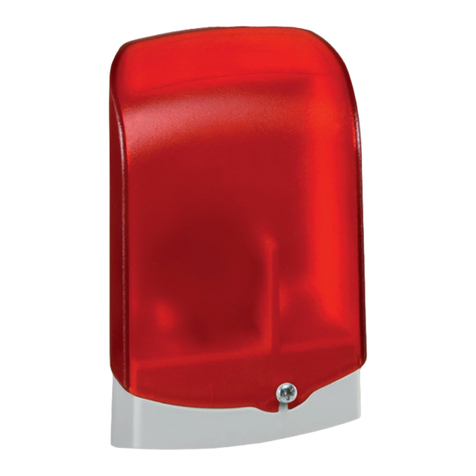
Resol AM1 User manual

AM1 alarm module
www.resol.com
RESOL AM1 alarm module
Mounting
Connection
Function
Manual
*48005020*
48005020
Thank you for buying this RESOL product.
Please read this manual carefully to get the best performance from this unit.
Please keep this manual carefully.

AM1 alarm module
© RESOL 09188_AM1_monus.indd
|2
Table of contents
Safety advice..............................................................2
Overview....................................................................3
Technical Data ...........................................................3
1. Mounting........................................................4
2. Connection....................................................4
3. Function.........................................................5
Imprint .......................................................................8
Subject to technical change. Errors excepted.
Description of symbols
Signal words describe the danger that may occur, when it
is not avoided.
Warning means that injury, possibly life-threatening injury,
can occur.
Attention means that damage to the appliance can occur.
Information about the product
Proper usage
The RESOL AM1 alarm module is to be used as an interface
for the failure signal transmission between RESOL devices
and external applications in compliance with the technical
data specified in this manual.
Improper use excludes all liability claims.
Note
Notes are indicated with an information symbol.
Arrows indicate instruction steps that should be→
carried out.
Safety advice
Please pay attention to the following safety advice in order
to avoid danger and damage to people and property.
Instructions
Attention must be paid to the valid local standards, regu-
lations and directives!
This manual contains important information about safe and
proper usage of this product. Please keep this manual for
future reference.
Target group
These instructions are exclusively addressed to authorised
skilled personnel.
Only qualified electricians should carry out electrical•
works.
Initial installation must be effected by qualified personnel•
named by the manufacturer
WARNING! Warnings are indicated with a
warning triangle!
They contain information on how→
to avoid the danger described.
Note
Strong electromagnetic fields can impair the
function of the device.
Make sure the device is not exposed to→
strong electromagnetic fields.
Disposal
Dispose of the packaging in an environmentally sound•
manner.
Dispose of old appliances in an environmentally sound•
manner. Upon request we will take back your old
appliances bought from us and guarantee an environ-
mentally sound disposal of the devices.

AM1 alarm module
© RESOL 09188_AM1_monus.indd
3 |
AM1 alarm module
The AM1 alarm module is designed to signal system failures. It is to be connected
to the VBus®of the controller and issues an optical signal via a red LED if a fai-
lure has occurred.The AM1 also has a potential-free relay output, which can e. g.
be connected to a building management system (BMS).Thus, a collective error
message can be issued in the case of a system failure.
Depending on the controller and the sensors connected,different fault conditions
can be signalled, e. g. sensor failures, excess or negative system pressure as well
as errors in the flow rate, such as a dry run of the pump.The AM1 alarm module
ensures that occurring failures can be immediately recognized and repaired,even if
the system and the controller are difficult to access or located in a remote place.
Thus, the reliability and the stable yield of the system are ensured.
Technical data
Housing: Plastic
Upper part of the housing:
PC 2207 UV
Base part of the housing:
Karilen E 42 D - H201
Protection type: IP 54
Ambient temperature: -13 ... +158 °F
Dimensions: 111 × 68 × 40 mm
Mounting: Wall mounting
Display: 1 LED
Power supply: via RESOL VBus®
Interface: RESOL VBus®
Output: 1 potential-free relay
Switching capacity: 30 VDC, 1 A;
125 VAC, 0,5 A
Included
AM1 alarm module•
accessory bag with•
2 × screws and wall plugs for wall
mounting
1 × terminal block
Overview
Reliable failure signal by LED•
Connection to a Building Management System (BMS) possible•
Supply and control via RESOL VBus•®
Sturdy and weatherproof housing in shapely design•
Simple installation•
64,07 mm
67,79 mm
111 mm
40 mm
34 mm
The AM1 can be connected to all
RESOL devices equipped with aVBus®.

AM1 alarm module
© RESOL 09188_AM1_monus.indd
|4
ATTENTION! Low voltage cables must not run to-
gether in a cable conduit with cables
carrying a higher voltage than 50V.
Pay attention to the local regula-→
tions!
ATTENTION! ESD damage!
Electrostatic discharge can lead to da-
mage to electronic components!
Take care to discharge properly→
before touching the inside of the
device!
The AM1 is designed for simple connection to RESOL
controllers or calorimeters via the RESOL VBus®. A power
supply connection is not necessary.
For easier access to the terminals, the circuit board can be
taken from its retaining fixture.
Connect the VBus®cable to the terminals marked „VBUS”
with either polarity.
To the terminals marked „REL”, a load can be connected
with either polarity. When connecting a load, observe the
switching capacity stated in the Technical data on pg. 3.
The bus cable can be extended with a two-wire cable
(bell wire).The cross section of the cable must be at least
0,5 mm2and the cable can be extended up to 50 m in the
case of a single connection.
2. Connection
Terminals of the AM1
Lower part of the housing
1. Mounting
To mount the AM1, proceed as follows::
Unscrew the housing screw and pull off the upper part→
of the housing upwards
Mark the fastening points on the wall (centres 5 cm)→
and drill the necessary holes
Screw the lower part of the housing to the wall using→
the screws and wall plugs from the accessory bag
Relocate the upper part of the housing and refasten it→
Upper part of the housing
Note
If a moisture protection is necessary, mount the
device vertically.

AM1 alarm module
© RESOL 09188_AM1_monus.indd
5 |
The AM1 alarm module is an interface for the failure signal
transmission between RESOL devices and external appli-
cations. It is to be connected to a RESOL controller or
calorimeter via the RESOL VBus®.
When theAM1 is operational,the LED will glow continuously
to signal operational readiness.
If the LED does not glow, check the connection of the→
device!
The AM1 receives and processes the VBus®data packets
of the device connected. In the case of an incoming failure
signal, the integrated LED flashes and the AM1 operates a
potential-free relay.
The relay can e. g. be used to connect an additional signal-
ling device, or to connect to a building management system
(BMS).The failure signals can thus be issued as a collective
error message by the BMS.
3. Function

AM1 alarm module
© RESOL 09188_AM1_monus.indd
|6
Notes

AM1 alarm module
© RESOL 09188_AM1_monus.indd
7 |
Notes

AM1 alarm module
© RESOL 09188_AM1_monus.indd
|8
Distributed by:
Please note:
The design and the specifications may be changed without notice.
The illustrations may differ from the original product.
RESOL - Elektronische Regelungen GmbH
Heiskampstraße 10
45527 Hattingen / Germany
Tel.: +49 (0) 23 24 / 96 48 - 0
Fax: +49 (0) 23 24 / 96 48 - 755
www.resol.com
info@resol.de
Reprinting / copying
This mounting- and operation manual including all parts is
copyrighted. Another use outside the copyright requires
the approval of RESOL - Elektronische Regelungen GmbH.
This especially applies for copies, translations, microfilms
and the storage into electronic systems.
Editor: RESOL - Elektronische Regelungen GmbH
Important notice:
The text and drawings in this manual are correct to the
best of our knowledge.. As faults can never be excluded,
please note: Your own calculations and plans, under consi-
deration of the current standards and national regulations
should only be basis for your projects.We do not offer a
guarantee for the completeness of the drawings and texts
of this manual - they only represent some examples.They
can only be used at your own risk. No liability is assumed
for incorrect, incomplete or false information and / or the
resulting damages.
Other manuals for AM1
2
Table of contents
Other Resol Security System manuals