Titan Pulsite Link User manual

2
© Titan Enterprises Ltd www.flowmeters.co.uk
PulsiteLink_Instruction_Manual_0722
Part number: 370-008
Document ID: PulsiteLink_Instruction_Manual_0722
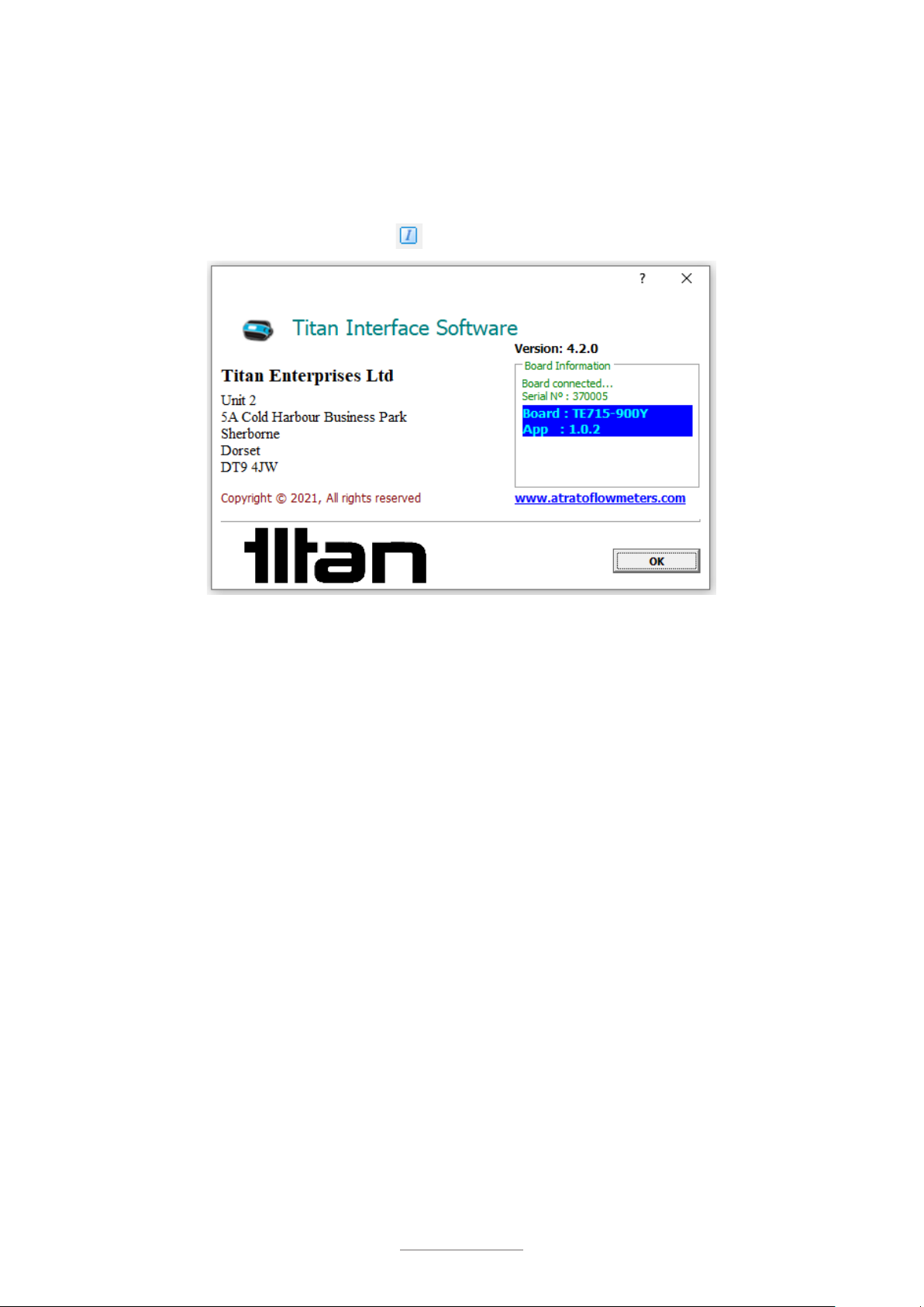
These instructions are intended for use with the Pulsite Link installed with App Version 1.0.2
or higher; and the Interface Software Version 4.2.0 or higher.
To view the version number, click the button
Intended use:
•
The Pulsite Link pulse convertor is intended for use with pulse output devices, such as:
o
NPN
o
PNP
o
Reed Switch
•
The Pulsite Link pulse convertor can provide linearized outputs of
o
4-20mA (active)
o
0-5V
o
0-10V
o
NPN and PNP
•
The Pulsite Link pulse convertor can also provide
o
Flow alarm switches via NPN and PNP output terminals
Disclaimer:
This information has been reviewed and believed to be correct at the time of publication. Titan
Enterprises holds no responsibility for any inaccuracies. The material in this document is for
information purposes only.
Storage:
The equipment should be stored in its original packaging in a non-hazardous area. Care must
be taken to ensure it is not subjected to extremes of temperature or humidity. Store away from
solvents.
General Safety:
Installation should be done by competent personnel who understand the electrical and
mechanical requirements of electronic flow metering devices.
Equipment must be protected from electric shock, fire and solvents.

3
© Titan Enterprises Ltd www.flowmeters.co.uk
PulsiteLink_Instruction_Manual_0722
ATTENTION:
Please read this instruction manual carefully before installation and operation of this device by
competent personnel.
Failure to follow these guidelines may result in damage to the equipment or personal injury.
Manufacture Information:
The Pulsite Link pulse convertor is designed and manufactured by:
Titan Enterprises Ltd, Unit 2, 5A Coldharbour Business Park, Sherborne, Dorset,
United Kingdom. DT9 4JW.
And conforms to:
•
CE
o
EMC Directives (2004/108/EC) EU Directive (2014/30/EU)
•
UKCA
o
Electromagnetic Compatibility Regulations 2016

4
© Titan Enterprises Ltd www.flowmeters.co.uk
PulsiteLink_Instruction_Manual_0722
1 General
•
The Pulsite Link pulse convertor is intended for use pulse output devices, such as:
o
NPN
o
PNP
o
Reed Switch
•
The Pulsite Link pulse convertor will provide linearized outputs of
o
4-20mA (active)
o
0-5V
o
0-10V
•
The Pulsite Link pulse convertor can also provide
o
Flow alarm switches via NPN and PNP output terminals
2 Installation
The electronics are held in an IP54 polymer case which can be mounted into a panel or using
the brackets provided.

6
© Titan Enterprises Ltd www.flowmeters.co.uk
PulsiteLink_Instruction_Manual_0722
3 Electrical
Electrical and instrument connections are wired internally via 2 x PG7 Cable glands and 5mm
pitch terminal block connectors.
To access these connectors, simply undo the 4 rear screws and carefully remove the front
cover.
Description
Specification
Terminal Connection
Power Supply
15-24Vdc Regulated
0.1 amp
+24VDC →Power Input +V
0VDC →Power Input 0V
Flowmeter Input
Pulse (max. 5kHz)
Reed Switch (max. 400Hz)
+VDC Supply to meter →Flowmeter +5V Out
0VDC Supply to Flowmeter →Flowmeter 0V
Pulse from flowmeter →Flowmeter
Sensor Supply 5Vdc 50mA max
room temperature. (25mA at
high temperature)
Pull up/down resistor required for NPN/PNP –see
wiring diagrams
Output Pulse
NPN/PNP 2.5kHz
24V@20mA max.
Scalable pulse per litre
Pulse Output to PLC/display →Digital Output
NPN or PNP
Pull up/down resistor required for NPN/PNP –see
wiring diagrams
Output Analog
0-5Vdc / 0-10Vdc
16 bit
Adjustable flow range
+VDC to PLC/Display →Analog Output V Out
0VDC of circuit →Analog Output 0V
4-20mA ACTIVE
16 bit
Adjustable flow range
+mA to PLC/Display →Analog Output mA Out
0VDC of circuit →Analog Output 0V

10
© Titan Enterprises Ltd www.flowmeters.co.uk
PulsiteLink_Instruction_Manual_0722
4 Interface Setup
4.1 Connecting Meter to PC
Before use, download and install the Titan Interface Software from memory stick or the
www.Flowmeters.co.uk website
The Pulsite Link should be set up using the USB interface and a suitable windows-based
computer.
Below is a screen shot of the opening Software screen:
NOTE: When correctly connected the bars will rotate in the bottom left had corner and you should see
“All Controls enabled”
On connecting Pulsite Link the Software will normally automatically load the settings
currently saved in the memory of the connected meter. The user can use the spy
glass icon to automatically pull the meter saved settings at any time.
From this software the user is able to configure all options of the meter. Detailed descriptions
follow, but if the user hovers the mouse over a menu item, a brief description will be displayed
to help.

11
© Titan Enterprises Ltd www.flowmeters.co.uk
PulsiteLink_Instruction_Manual_0722
4.1.1 Connecting Multiple Titan Devices
If more than one meter is connected to the same PC, when starting, the Interface Software will
open the window to choose which you wish to connect:
By opening another copy of the Titan Interface Software you can connect and modify multiple
meters from the same computer.
The panel below shows the main menu function icons of the Interface as seen on the top left-
hand bar of the screen.
Save settings to meter’s non-volatile memory
Retrieve settings from meter
Load settings from a file on the computer
Test outputs
Save settings to a file on the computer
Software Information

12
© Titan Enterprises Ltd www.flowmeters.co.uk
PulsiteLink_Instruction_Manual_0722
4.1.2 Retrieve Settings from Meter
When connected the settings will normally be automatically retrieved from the meter. If this is
not the case, or the user wishes to check the meter saved settings against those shown in the
software, they can be retrieved from the nonvolatile memory of the flow meter by pressing the
looking glass icon.
4.1.3 Test Outputs
This tab enables the user to manually set
outputs on the Pins for testing to the
target device.
Once the required output is selected click
the “Start Test” button and all pins will
give the selected output rate for 23
seconds.
4.1.4 Software Information
This displays the current software version
of the Interface software and the flow meter
connected.

13
© Titan Enterprises Ltd www.flowmeters.co.uk
PulsiteLink_Instruction_Manual_0722
4.2 Window Tab Descriptions
On connection with the Titan Interface Software a window will open with two tabs of settings
and information:
User Settings: Here you can
configure how you wish the
meter to present the flow and
outputs.
Flow Details: Shows the user
real time data from the meter
including flow and outputs.
Multiple Window Display
To aid set up whilst operating the meter it is possible to detach the Flow Details and
Advanced windows by dragging and dropping the bottom tabs away from the main window.
This allows the user to view those tabs whilst adjusting the User Settings.
To return all windows to docked Mode use the View drop down menu, Restore Defaults

14
© Titan Enterprises Ltd www.flowmeters.co.uk
PulsiteLink_Instruction_Manual_0722
4.3 User Settings Tab
4.3.1 Calibration Settings
Units: A drop down menu offers the choice of - Litres, ml,
gms, kg, US gallon, Imperial gallon or Custom units i.e. blank.
Note that the Custom Units setting will be equivalent to Litres if no
modifications are made to scale factor.
Rate (units per): This is the time base for the flow rate and
has the option of Second, Minute or Hour.
Scale Factor Adjustment: This allows the user to adjust or
tune the calibration flow value if required.
Density: The flowmeter is fundamentally a volumetric device,
but a density figure can be entered here if one of the mass
units is selected. Caution must be used however, as there is
no temperature/density correction.
Cut Off: Flow values below this level will be set to zero.
4.3.2 Pulse Input Configuration
Reed Relay: Use when connecting a Reed relay flow
meter.
When ticked this provides an additional extended filter in
which a logic high signal must be high for at least 560μs
before it is propagated; whereas a logic zero is propagated
immediately. This is intended for a circuit in which the reed
relay switches to ground with a pull-up resistor.
Detection: Pulse detection can be chosen for Rising edge;
Falling edge or Both edges.
“Both edge”detection measures both the rising and falling
edges

15
© Titan Enterprises Ltd www.flowmeters.co.uk
PulsiteLink_Instruction_Manual_0722
Analog Response Time: This selects the rate that the
analog output and asynchronous pulse outputs are
updated.
Chose the slowest required for the lowest frequency of input
pulses expected to be seen. Hovering your mouse over the
Cut Off value will give a recommended lowest flow for the
input calibration k factor and the chosen Analog Response
Time.. Setting the cut-off value below the recommended
level means when the flow is between the set value and the
recommended value, the display will occasionally read
zero.
K Factor Values: Enter the values of flow and pulses per
litre (K factor) as found in the calibration certificate supplied
with your flow meter.
4.3.3 External Connections:
Within this section the user can configure pulse, analog and alarm outputs.

16
© Titan Enterprises Ltd www.flowmeters.co.uk
PulsiteLink_Instruction_Manual_0722
4.3.3.1.1 Pin Assignments:
The options for each PIN are: Not Used Input or Output
Each of the PIN Assignments can be configured as an
output function or not used
The operation to modify NPN Output and PNP Output
is identical within the software, with the exception of the
type of transistor pulse output.
The options for each PIN, are:
Not Used or Output
NOTE: These instructions are the same for NPN and PNP with the exception of the transistor
wiring and operation.
For example: For NPN the idle state is switch ‘open’ which will be a high Volt output if there is
a pull-up in the circuit. PNP would be the opposite, at zero Volt.
4.3.3.2 NPN Output / PNP Output
If Output is selected in Pin assignments, the output options are:
•Pulse
•Single or Dual flow alarm
4.3.3.2.1 Pulse:
Enter the number of pulses per unit volume
required. This figure can be adjusted to suit the
application and the flow range required from the
meter.
The maximum output frequency is 5000 Hz so care
must be taken to ensure that this pulse rate is not
exceeded.
NOTE:
Details of how to connect the outputs can be found in Section 3.1.1
There are two options for the Pulse Output:
•Asynchronous
In this mode the meter measures
according to the analog response time
and sends pulse (NPN/PNP) output
after that period at 50:50 ratio.
•Synchronous
In this mode the Pulse output
(NPN/PNP) is sent directly on receipt of
the second pulse edge received.
The pulse output is direct 50:50 ratio or
can be set to a specific pulse width(ms).

17
© Titan Enterprises Ltd www.flowmeters.co.uk
PulsiteLink_Instruction_Manual_0722
4.3.3.2.2 Single Flow Alarm:
Checking this option opens up input boxes for
Threshold
, Hysteresis
and
Invert.
•Set the
Threshold
to the flow value you require the
transistor to operate.
•The logic of operation can be adjusted with the
Invert
check box.
Hysteresis (%)
: This is used to prevent “fluttering” of
the alarm signal when flow is around the threshold
level.
The % value is set around the Threshold value.
For example: Threshold Set at 1.0 and Hysteresis at
20%. The Pin will turn ON at 1.1 and off at 0.9.
NOTE: The INVERT checkbox will reverse the
action of the alarm output.
For details for each PIN see the or hover mouse over the set point to see the action of the
output with the chosen settings.

18
© Titan Enterprises Ltd www.flowmeters.co.uk
PulsiteLink_Instruction_Manual_0722
4.3.3.2.3 Dual Flow Alarm:
Checking this will enable a range of flow to be
entered. When the flow is outside/inside of this
range the alarm will be triggered.
The remaining settings in the input box are the
same as for Single Flow alarms.
•The alarm will automatically activate and
reset in proportion to the user set
Hysteresis of the Threshold levels.
•The INVERT checkbox will reverse the
action of the alarm output. (See the Alarm
Logic Table).
For details for each PIN see the Alarm logic table or hover mouse over the set point to see the
action of the output with the chosen settings.

19
© Titan Enterprises Ltd www.flowmeters.co.uk
PulsiteLink_Instruction_Manual_0722
4.3.3.3 Alarm Logic Table
Flow Alarm
Invert
Alarm Action
Below Threshold
Above Threshold
Single
Unticked
OFF
ON
Single
Ticked
ON
OFF
In Range
Outside Range
Dual
Unticked
ON
OFF
Dual
Ticked
OFF
ON
NOTE: The NPN and PNP have different outputs when used due to their wiring.
•Using the NPN: OFF =Powered +VDC and ON = Unpowered 0VDC
•Using the PNP: OFF=Unpowered 0VDC and ON = Powered +VDC
4.3.3.4 Analog Outputs
NOTE: FOR FULL ANALOG OUTPUT FUNCTION EXTERNAL POWER OF >15VDC IS
REQUIRED
Analog Output: there are four options on the
drop-down menu:
•Not Used
•4-20mA (active)
•0-5 Volt
•0-10 Volt.
NOTE: The 4-20mA is ACTIVE (Not loop powered).
Incorrect wiring may damage this device
Once the Analog Mode selection has been
made you can enter the low and high flows
for the analog outputs as required. These are
numeric entries in the units and time base
selected in calibration settings.

20
© Titan Enterprises Ltd www.flowmeters.co.uk
PulsiteLink_Instruction_Manual_0722
4.4 Flow Details Tab
The Flow Details tab displays the performance of the meter in real time.
The main large display reflects the meter readings showing on the Atrato LCD Display, if fitted,
and will mimic that display. The buttons either side have the functions selected on the
‘Configuration’ screen and work in parallel with the buttons on the Atrato flowmeter display unit
itself.
The Results Details indow below the rate and total display shows various relevant operational
parameters whilst the unit is operating, e.g., relay status and frequency output if these options
are selected.
Parameters:
•Flow: This is the instantaneous flow rate and is updated approximately every 100
milliseconds.
•Input: The measured frequency of pulses from the connected flowmeter/device.
•NPN Output & PNP Output: If no selection is made “Not used” will be in the Description
column. See following text and chart for the display legends.
oOR: When NPN or PNP is set to “Output” and set to “Pulse” this will display the
frequency of the running output and the number of pulses per litre selected.
oOR: If it is selected to “Output” and set to “Flow switch” the Value column will
show the transistor status either “low” or “high” and the notes will show the
selected switch points.
•Analog: Displays the chosen analog output and value.
Other manuals for Pulsite Link
1
Table of contents
Other Titan Industrial Equipment manuals