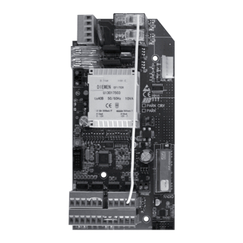
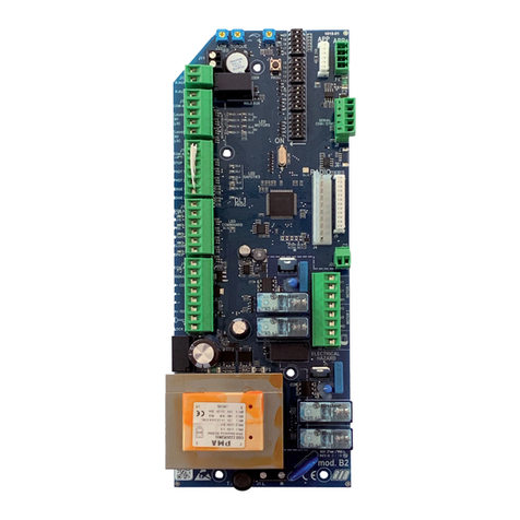
RIB MINI TS User manual

ISTRUZIONI PER L'USO E L’INSTALLAZIONE
OPERATING AND INSTALLATION INSTRUCTIONS
Mod. MINI TS
COD. ACG2265
Pag. 1 di 8
QUADRO DI COMANDO PER 1 MOTORE A 230 Vac PER TENDE DA SOLE
ONE 230Vac MOTOR CONTROL PANEL FOR SUNSHADES
ATTENZIONE: LEGGERE ATTENTAMENTE LE ISTRUZIONI
PRIMA DI INSTALLARE IL QUADRO DI
COMANDO!!!
CAUTION:DO NOT INSTALL THE CONTROL PANEL
UNLESS YOU HAVE READ THE INSTRUCTIONS
FIRST!!!
ATTENZIONE!
INSTALLAZIONE
Alcuni punti della scheda elettrica sono sottoposti a tensioni pericolose.
L’installazione e la programmazione del quadrò andrà pertanto svolta solamente da
personale qualificato.
Prevedere l’uso di un dispositivo di sicurezza che assicuri la sconnessione della
centralina dall’alimentazione per effettuare manutenzioni.
Ciò può essere effettuato utilizzando per esempio un interruttore bipolare
automatico manetotermico a norma, adeguato all’assorbimento di corrente del
motore installato.
Utilizzare cavi a norma per la parte di potenza, con una sezione adeguata
all’assorbimento di corrente del motore installato.
WARNING!
INSTALLATION
Dangerous voltage is applied to some point of the electrical card: installation and
setting of control panel must be performed by trained personnel only.
A safety device should be installed to ensure disconnection of the control unit from
the main supply during maintenance operations.
Such feature can be obtained through an approved thermal breaker, two pole,
adequate to the current demand of the motor as installed.
Use conductors of approved type for the power circuit, with adequate section for the
current demand of the motor as installed.
Il quadro di comando MINI TS é un’apparecchiatura universale adatta a gestire
l’azionamento ed il controllo di tende da sole in modo semplice e completo. Questo
prodotto comanda motori a 230V in corrente alternata fino a 500W (max) di
potenza.
La logica della MINI TS offre la possibilità di gestire:
- la rilevazione della velocità del vento
- l’intensità della luce
- la rilevazione della pioggia
consentendo di aprire e/o chiudere la tenda da sole in modo completamente
automatico in base alle condizioni metereologiche presenti.
The MINI TS control panel is a universal apparatus designed to manage sunshade
activation and control in a simple and complete manner and to meet any kind of
requirement. This product controls 1-phase 230V motors up to a power of 500W
(max)
The logic of the MINI TS program offers the possibility of managing:
- wind speed detection
- light power
- rain detection
making if possible to open and/or close the sunshade in a completely automatic
manner, depending on current weather conditions.
CARATTERISTICHE TECNICHE - TECHNICAL DATA
Tensione di alimentazione
Uscita motore
Assorbimento scheda
Tempo di lavoro motore
Tempo di attesa dopo allarme vento
Temperatura di funzionamento
230 Vac +10% - 15%
230 Vac 500W MAX cosj > 0,8
3W MAX (escluso accessori e utenze/(excluding accessories and utilities))
7 minuti/minutes
7 minuti/minutes
-10°C ÷ +60°C
Supply voltage
Motor outlet
Card consumption
Work schedule of the motor
Stand by time following wind alarm
Operating temperature
Grado di Protezione Protection Grade IP54

Pag. 2 di 8
COLLEGAMENTI ELETTRICI
I collegamenti elettrici della centralina MINI TS possono essere individuati da due blocchi di
morsetti a vite. Uno a 5 vie per l’alimentazione di rete e motore, e uno a 11 vie per i comandi ed i
segnali di controllo (Fig1).
Secondo lo schema rappresentato dalla figura qui di seguito:
1. Collegare il motore ai morsetti 12,13,14 presenti sulla scheda rispettando fedelmente lo
schema.
2. Collegare i cavi dell’alimentazione ai morsetti 15 e 16, prestando molta attenzione a
compiere questa operazione con la tensione di rete 230Vac disinserita.
Secondo lo schema rappresentato dalla figura qui di seguito:
1. Collegare i pulsanti apri e chiudi ai morsetti 1,2,3 rispettando lo schema e cercando di
mantenere tassativamente una certa distanza dai cavi di rete. Agli stessi morsetti é
possibile collegare anche il radioricevitore RIB bicanale (cod. ACG5052).
2. Collegare il sensore vento* (se presente) ai morsetti 6 e 7 facendo attenzione alle polarità.
* Alla centralina MINI TS é possibile collegare fino a quattro centraline ad un unico anemometro
utlizzando lo schema presente nella TAV.1 pag. 8.
3. Collegare il sensore luce (se presente) ai morsetti 8 e 9 facendo attenzione alle polarità.
T
ASTO APPRENDIMENTO
LED APPRENDIMENTO
ALLARME
LED MODALITA
’
MANUALE
MORSETTI ALIMENTAZIONE RETE E MOTOREMORSETTI COMANDI E ACCESSORI
LED LUCE ESTERNA
RILEVATA
REGOLAZIONE SOGLIA ALLARME VENTO
ALIMENTAZIONE 230VAC 50HZ
NON COLLEGARE LA SCHEDA DIRETTAMENTE ALLA RETE
ELETTRICA MA PREVEDERE UN DISPOSITIVO CHE POSSA
ASSICURARE LA DISCONNESSIONE ONNIPOLARE
DELL’ALIMENTAZIONE DELLA CENTRALINA
DEVIATORE DI FUNZIONE
(
DIP
-
SWITCH
)
Fig. 1
4. Collegare il sensore pioggia (se presente) ai morsetti 8 e 10 rispettando la polarità.
ITALIANO

Pag. 3 di 8
PANNELLO DI CONTROLLO
La centralina MINI TS é dotata di un pannello di controllo, con il quale é possibile monitorare il
suo stato di funzionamento. Il pannello di controllo é composto da tre spie luminose (Led):
- spia verde che segnala l’intensità della luce;
- spia gialla che indica il funzionamento in manuale (non implementato in questo modello);
- spia rossa che segnala la condizione di allarme.
Con questi indicatori luminosi, si può verificare il corretto funzionamento della centralina ed
individuare i possibili mal funzionamenti. A tale proposito rimandiamo al paragrafo relativo alle
anomalie.
Quando viene data tensione alla centralina, tutti i tre led indicatori rimarrano accesi per un
secondo, dopo di che si spegneranno. Dopo alcuni secondi, se é presente il sensore d’intensità
luminosa, il led verde comincerà a lampeggiare in modo differente a seconda dell’intensità di luce
registrata. Nel caso in cui si presenti una condizione d’allarme (vento o pioggia), il led rosso
comincerà a lampeggiare per tutto il periodo di allarme (circa 7 minuti dall’ultima registrazione
d’allarme).
Il led giallo é predisposto alla segnalazione del funzionamento dispositivo in modalità manuale
(in questo modello questa funzionalità non é implementata).
SCELTA DEL MODO DI FUNZIONAMENTO E REGOLAZIONI
Impostando il selettore di funzione (dip-switch) e il dispositivo di regolazione (trimmer) presenti
nella centralina, sono possibili vari tipi di funzionamento.
MINI TS viene consegnato con le seguenti impostazioni.
Applicando i vari dispositivi di controllo “ambientale” (anemometro, sensore d’intensità luminosa,
sensore pioggia), si possono effetturare delle ulteriori regolazioni, agendo direttamente sulla
scheda.
Agendo infatti sul dip-switch 1, una volta chiusa la tenda a causa della condizione
d’allarme “presenza forte vento” rilevata dall’anemometro e trascorsi 7 minuti
dall’ultima rilevazione sopra la soglia di sicurezza, é possibile selezionare:
a) se si desidera che la tenda venga automaticamente riaperta al ritorno delle normali
condizioni (posizione ON);
b) se dever imanere ferma in attesa di un comando proveniente dai pulsanti di marcia
o dal telecomando (posizione OFF).
Agendo sul dip-switch 2, rappresentato dalla figura accanto e presente nella scheda elettronica,
é possibile scegliere:
a) se si desidera che la tenda venga totalmente aperta (chiusa) con la semplice
pressione del pulsante di apertura (chiusura) (posizione ON);
b) se si preferisce che l’apertura (chiusura) sia direttamente legata alla pressione del
relativo pulsante, interrompendosi così al suo rilascio (posizione OFF).
N.B.: Nel caso a) dalla centralina viene eseguito l’ultimo comando fornito. Se
quindi la tenda é stata leggermente chiusa, la tenda non viene riaperta.
N.B.: In presenza del sensore luce, il comando da esso fornito ha la priorità sullo stato del
dip-switch 1. Quindi se dip-switch 1 é OFF e siamo in presenza di forte luce (sopra la
soglia di apertura), la tenda verrà riaperta.
LED ROSSO
LED GIALLO
LED VERDE
Nella centralina MINI TS, la suddetta soglia di sicurezza é impostata d un valore intermedio della
velocità del vento pari a 30 Km/h.
Tale velocità può essere variata da 0 a 62Km/h agendo sul dispositivo di regolazione (trimmer)
presente sulla scheda come rappresentato nella figura soprastante.
N.B.: La condizione “tenda aperta” é soddisfatta solo e soltanto nel caso in cui tutte le
condizioni di allarme impostate sono verificate. La presenza di un allarme
chiuderebbe istantaneamente la tenda e bloccherebbe ogni tipo di comando esterno
per 7 minuti; la tenda in questo modo rimarrebbe chiusa in attesa dell’uscita da tale
stato.
N.B.: Durante l’installazione, per evitare di attendere i 7 minuti dall’allarme ogni qualvolta
si facesse intervenire uno dei sensori di sicurezza, é possibile ripristinare il
funzionamento normale della centralina, una volta che la tenda si é chiusa,
premendo il tastino presente nella centralina.
MODIFICA DELLE IMPOSTAZIONI
La centralina MINI TS viene fornita con valori standard preimpostati (luce diurna e apertura totale
della tenda).
Nei luoghi con presenza costante di vento può essere utile agire sul punto di apertura della
tenda. L’aria può rappresentare un pericolo con la tenda completamente aperta; inoltre potrebbe
causare dei problemi quando la tenda stessa é aperta fino ad un determinato punto. Al cessare
dell’aria, sarà dunque possibile aprirla del tutto. Si tenga presente che un aumento del vento al di
sopra della soglia d’allarme consentita porterebbe automaticamente alla chiusura della tenda.
INTENSITA’ LUMINOSA PER L’APERTURA AUTOMATICA
Attenzione al comportamento del LED VERDE presente sul coperchio.
Con questo si può istantaneamente intuire in quali condizioni di luminosità si trova la centralina.
LED VERDE SEMPRE SPENTO => Il valore di luminosità rilevato dal sensore luce é minore (é
più buio) del valore minimo di luce impostato.
LAMPEGGIO LENTO DEL LED VERDE
(1 volta ogni due secondi circa) => Il valore di luminosità rilevato dal sensore luce si trova
compreso tra il valore minimo e il valore massimo di luce
impostato.
AUMENTO DELLA SOGLIA DI SICUREZZA
DIMINUZIONE DELLA SOGLIA DI SICUREZZA

Pag. 4 di 8
ATTENZIONE
E’ possibile in ogni momento reimpostare i valori di fabbricazione immessi
da RIB resettando la scheda. Per il reset della scheda é sufficiente togliere
tensione alla centralina e successivamente tenendo premuto il
TASTO DI
APPRENDIMENTO
per alcuni secondi, ridare tensione. Il LED ROSSO
dell’apprendimento farà un lampeggio breve ed uno prolungato dopo di che
si spegnerà.
LAMPEGGIO VELOCE DEL LED VERDE
(2 volte ogni secondo circa) => Il valore di luminosità rilevato dal sensore luce é maggiore (é più
chiaro) del valore massimo di luce impostato.
PROBLEMI
1) Nell’istante dell’accensione della centralina tutti i LED (rosso,
giallo, verde) non si accendono per 1 secondo.
2) Pigiando il TASTO D’APPRENDIMENTO non si accende il LED
ROSSO della centralina
3) Il led rosso continua a lampeggiare.
4) La tenda non si apre automaticamente.
5) La tenda non si chiude automaticamente.
6) Dopo un allarme vento o pioggia la tenda non si riapre.
CAUSE
➾ Manca la corrente.
➾ La spina non é inserita.
➾ Il collegamento alla rete elettrica é assenta.
➾ Il dispositivo di sicurezza per il disinserimento della tensione
é intervenuto.
➾ Centralina non funzionante.
➾ Allarme pioggia attivo (bagnato).
➾ Sensore pioggia guasto.
➾ Allarme vento attivo.
➾ Sensore vento guasto.
➾ Luminosità esterna bassa (LED VERDE spendo o con
lampeggio lento).
➾ Motore tenda non funzionante (LED VERDE lampeggio
veloce).
➾ Centralina non funzionante
➾ Luminosità esterna elevata (LED VERDE con lampeggio
veloce).
➾ Motore tenda non funzionante (LED VERDE spento).
➾ Centralina non funzionante
➾ LED ROSSO lampeggiante
➾ Dip-switch 1 in posizione OFF
➾ L’ultimo movimento compiuto dalla tenda é stato un
movimento di chiusura
➾ Centralina non funzionante
➾ Motore tenda non funzionante
RIMEDI
➾ Attendere che venga ripristinata.
➾ Inserire la spina.
➾ Controllare i collegamenti.
➾ Controllare i collegamenti e ripristinare il dispositivo.
➾ Verificare punto 1).
➾ Contattare il tecnico installatore.
➾ Attendere che le condizioni atmosferiche migliorino e i 7
minuti per il ripristino automatico.
➾ Controllare la corretta installazione del sensore (per esempio
lontano da sorgenti di condensa).
➾ Contattare il tecnico installatore per la sostituzione del
sensore.
➾ Attendere che le condizioni atmosferiche migliorino.
➾ Controllare la corretta installazione del sensore (per esempio
vicinanza a bocche di areazione).
➾ Contattare il tecnico installatore per la sostituzione del
sensore.
➾ Controllare la corretta installazione del sensore di luminosità
(per esempio lontano da oggetti o cose che fanno ombra).
➾ Contattare il tecnico installatore
➾ Verificare punti 1), 2), 3).
➾ Contattare il tecnico installatore
➾ Controllare la corretta installazione del sensore di luminosità
(per esempio lontano da oggetti o cose che fanno ombra).
➾ Contattare il tecnico installatore
➾ Verificare punti 1), 2), 3), 4).
➾ Contattare il tecnico installatore.
➾ Attendere 7 minuti dall’ultima rilevazione dell’allarme.
➾ Posizionare il Dip-switch 1 in posizione ON
➾ L’ultimo comando deve essere di apertura
➾ Contattare il tecnico installatore
ANOMALIE

Pag. 5 di 8
ELECTRICAL CONNECTION
The electrical connection of the control unit MINI TS is provided trough two screw blocks. The
first, 5 contact type, for main and motor supply, and the second, 11 contact type, for the controls
and monitoring signals (Fig. 1).
According to the schematic as illustarted in following figure:
1. Connect the motor to the contacts 12, 13, 14 on the card following thoroughly the
schematic.
2. Connect the main supply conductors to the blocks 15 and 16, paying utmost attention to
perform such operation with the main power 230 Vac disconnected.
According to the schematic as illustrated in following figure:
1. Connect the buttons open and close to blocks 1,2,3 following the schematic and paying
attention to provide mandatorily a suitable distance from the main supply conductors. The
radio receiver RIB two channel (cod. ACG5052)can be connected to the same contact
blocks.
2. Connect the wind sensor* (if installed) to contact bocks 6 and 7 ensuring the correct
polarity is observed.
* It is possible to connect up to 4 control units to a single anemometer, as per schematic
ALARM
PROGRAMMING LED
LED MANUAL MODE
CONTACT BLOCKS FOR MAIN IN AND MOTORCONTACT BLOCKS FOR CONTROLS
AND ACCESSORIES
LED EXTERNAL LIGHT
DETECTION
SETTING OF WIND ALARM TRESHOLD
SUPPLY 230VAC 50HZ
DO NOT CONNECT THE CARD DIRECTLY TO THE MAIN
SUPPLY, BUT THROUGH A SUITABLE DEVICE FOR TOTAL
DISCONNECTION OF THE CONTROL UNIT.
FUNCTION CHANGE OVER SWITCH
(
DIP
-
SWITCH
)
Fig. 1
provided with TABLE 1, page 8.
3. Connect the light sensor (if installed) to contact blocks 8 and 9 ensuring the correct
polarity is observed.
4. Connect the rain sensor (if installed) to contact blocks 8 and 10 ensuring the correct
polarity is observed.
ENGLISH
PROGRAMMING BUTTON

Pag. 6 di 8
CONTROL PANEL
The control unit MINI TS is provided with a panel for operation monitoring. The control panel
includes three lamps (Led):
- green lamp indicates the light intensity as sensed by the control system;
- yellow lamp indicates the manual mode of operation (not included in this model);
- red lamp signals a warning condition.
The above lamps allow monitoring the correct operation of the control unit, and the detection of
any failure. For more details see the paragraph relevant to the anomalies.
Upon connection of the control unit to the main supply, all three leds lit for one second, then will
turn off. After a few seconds, in case the light sensor is installed, the green led will start flashing
with a frequency related to the light intensity as sensed. In case a warning condition is detected
(wind or rain), the red led will flash for the whole alarm time (about 7 minutes from the last
warning indication).
The yellow led is provided for the monitoring of unit operation in manual mode (this feature is
not implemented in this model).
SELECTION OF OPERATION MODE AND SETTING
A number of operation modes can be selected through setting of the function selector (dip-switch)
and the adjusting device (trimmer) installed in the control unit.
MINI TS is supplied with the following factory settings.
Upon installation of different “environmental” control devices (anemometer, light sensor, rain
sensor) further settings can be performed, through direct card adjustment.
Adjustment of dip-switch 1 allows the selection of two operation modes following a warning
condition “strong wind alarm” as detected by the anemometer on elapsing of 7
minutes from the last triggering of the safety treshold, as follows:
a) the awning will automatically extend on restoring of normal conditions (position
ON);
b) the awning will remain retracted until further commands are selected through the
operation buttons or the remote control (position OFF).
Adjustment of dip-switch 2, as illustrated in the nearby figure and installed on the electronic
card, allows the selection of following operation modes:
a) the awning will completely extend (retract) upon momentary operation of the extend
(retract) pushbutton (position ON);
b) the awning will extend (retract) as long as the relevant pushbutton is depressed.
The travel will stop on release of the pushbutton (position OFF).
NOTE: With setting a) the control unit performs the last command received. In
case the awning has hence been partially retracted, it will not extend.
NOTE: If the light sensor is fitted, its function prevails over the dip-switch 1. Therefore in
case the dip-switch is set to OFF and a strong light condition is detected (above
the extend treshold), the awning will extend.
RED LED
YELLOW LED
GREEN LED
In the control unit MINI TS, the above safety treshold is set at an average wind velocity of 30
Km/h.
Such velocity treshold can be adjusted from 0 to 62 Km/h through the setting device (trimmer)
installed on the card as illustrated in the figure above.
NOTE: The condition “awning extended” is reached only in case all the alarm conditions
as set are not triggered. The monitoring of a warning will instantaneously cause the
awning to retract and the deactivation of any external imput for 7 minutes; in such
occurrence the awning would remain retracted until the normal conditions are
restored.
NOTE: During the installation, to avoid waiting 7 minutes from an alarm upon triggering
any safety sensor, it is possible to reset the normal operation mode of the control
unit, following awning retraction, by depressing the small pushbutton inside the
control unit itself.
MODIFICATION OF SETTINGS
The control unit MINI TS is supplied with a standard setting (day light and complete awning
extension).
In places with constant presence of wind it could be useful to adjust the awning extension stroke.
The wind can damage a completely or partially extended awning, depending on the velocity. On
wind decreasing it will be possible to completely extend the awning. Please note that a wind
speed above the safety treshold would automatically cause the awning to retract.
LIGHT INTENSITY FOR AUTOMATIC EXTENSION
Note the operation of the GREEN LED on the unit cover.
It allows instantaneous monitoring of the light intensity as sensed by the unit.
GREEN LED OFF => The light intensity as sensed by the light sensor is lower (darker) than the
minimum light setting.
INCREASING OF THE SAFETY TRESHOLD
DECREASING OF THE SAFETY TRESHOLD

CAUTION
It is always possible to modify the factory setting as performed by RIB by
resetting the card. To reset the card cut off the unit supply and while
maintaining depressed the storing pushbutton for a few seconds, reconnect
the supply to the unit. The storing RED LED will show a short flash followed
by a prolonged one, and will extinguish.
FAILURES
1) Upon unit switching on all leds (red, yellow, green) will not lit
for 1 second.
2) On depressing the storing pushbutton the unit RED LED will
not lit.
3) The red led keeps flashing.
4) The awning does not extend automatically.
5) The awning does not retract automatically.
6) On restoring of safety conditions, following a wind or rain
alarm, the awning does not extend
CAUSES
➾ Power failure.
➾ Plug not fitted corredctly.
➾ Interruption of the main power connection.
➾ Tripping of safety breaker.
➾ Control unit failure.
➾ Triggering of rain alarm (wet).
➾ Failure of rain sensor.
➾ Triggering of wind alarm.
➾ Failure of wind sensor.
➾ Low external light level (GREEN LED off or flashing slowly).
➾ Failure of awning motor (GREEN LED flashing quickly).
➾ Failure of the control unit
➾ High external light level (GREEN LED flashing quickly).
➾ Failure of awning motor (GREEN LED off).
➾ Failure of the control unit.
➾ RED LED flashing.
➾ Dip-switch 1 in position OFF.
➾ The last stroke as performed by the awning has been a
retraction.
➾ Failure of the control unit
➾ Failure of the awning motor
REMEDIAL ACTIONS
➾ Wait a reset.
➾ Fit the plug.
➾ Verify the connections.
➾ Verify the connections and reset the device.
➾ Verify step 1).
➾ Get assistance from the installation technician .
➾ Wait for an atmosferic conditions improve and elapsing of 7
minutes for automatic reset.
➾ Verify the correct installation of the sensor (apart from
condensation sources).
➾ Call the installation technician for sensor replacement.
➾ Wait for an atmosferic conditions improve.
➾ Verify the correct installation of the sensor (apart from
ventilation ports).
➾ Call the installation technician for sensor replacement.
➾ Verify the correct installation of the light sensor (out of any
object shadow).
➾ Call the installation technician.
➾ Verify steps 1), 2), 3).
➾ Call the installation technician.
➾ Verify the correct installation of the light sensor (out of any
object shadow).
➾ Call the installation technician
➾ Verify steps 1), 2), 3), 4).
➾ Call the installation technician
➾ Wait elapsing 7 minutes from the last alarm triggering.
➾ Set the Dip-switch 1 in position ON
➾ The last command must be to extend
➾ Call the installation technician
GREEN LED SLOW FLASHING
(about 1 flash every two seconds) => The light intensity as sensed by the light sensor is between
the minimum and maximum light setting.
GREEN LED QUICK FLASHING
(about 2 flashes every second) => The light intensity as sensed by the light sensor is higher
(brighter) than the maximum light setting.
Pag. 7 di 8
ANOMALIES

Cod. CVA1524 - 11052004 - Rev. 02
25014 CASTENEDOLO (BS)-ITALY
Via Matteotti, 162
Telefono ++39.030.2135811
Telefax ++39.030.21358279-21358278
automatismi per cancelli
automatic entry systems
®
8 028265 100138 >
TAV. 1 N.B.: Alla centralina MINI TS é possibile collegare fino a quattro centraline ad un unico anemometro utilizzando lo schema sotto raffigurato.
TAB. 1 NOTE: It is possible to connect up to four control units MINI TS to a single anemometer, as per schematic supplied .
Pag. 8 di 8
Green conductor
White conductor
ANEMOMETER
Other manuals for MINI TS
1
This manual suits for next models
1
Table of contents
Languages:
Other RIB Controllers manuals
Popular Controllers manuals by other brands

A-T Controls
A-T Controls TRIAC FSE Series Installation and maintenance manual

Mitsubishi Electric
Mitsubishi Electric Central Controller G-50A Instruction book

Pentair
Pentair KEYSTONE EPI-2 Installation and maintenance instructions

AUMA
AUMA SAEx 25.1 Operation instructions

HP
HP ProCurve MSM765zl Installation and getting started guide

Rain Bird
Rain Bird IQNCCEN Installation/configuration