RIB TOUCH Wi-Fi User manual

TOUCH Wi-Fi code ACG3016
Brevettato - Patented EP10711748 - WO2010095160
ITALIANO pag. 02 / FRANÇAIS pag. 08 / ENGLISH page 14 / DEUTSCH pag. 20 / ESPAÑOL pag. 26
Batterie AA non incluse - Piles AA non incluses - AA batteries not included
AA Batterien nicht beiliegend - Baterías AA no incluidas
COSTA MECCANICA SENZA FILI
DISPOSITIVO DI PROTEZIONE Wi-Fi PER ORGANI IN MOVIMENTO - CERTIFICATO EN 13849-2 (2008) - Ref. n. 10.027 - CATEGORIA 2
NON POSIZIONARE LA SCHEDA DI GESTIONE MASTER Wi-Fi DIETRO A MURI, PANNELLI METALLICI O
ALTRI TIPI DI OSTACOLI CHE POSSANO IMPEDIRE LA COMUNICAZIONE RADIO CON TOUCH Wi-Fi
BARRE PALPEUSE MÉCANIQUE SANS FIL
DISPOSITIF DE PROTECTION Wi-Fi POUR ORGANES EN MOUVEMENT - CERTIFIÉ EN 13849-2 (2008) N. 10.027 CATÉGORIE 2
NE PAS POSITIONNEZ LA FICHE DE GESTION MASTER Wi-Fi DERRIÈRE DES MURS, PANNEAUX
MÉTALLIQUES,OUAUTRESTYPESD’OBSTACLESQUIPOURRAIENTCOMPROMETTRELATRANSMISSION
RADIO AVEC TOUCH Wi-Fi.
MECHANICAL STRIP WITHOUT WIRES
Wi-Fi SAFETY DEVICE FOR PROTECTION FROM MOVING ELEMENTS - CERTIFIED EN 13849-2 (2008) NO. 10.027 CATEGORY 2
DO NOT INSTALL MASTER Wi-Fi RECEIVER CARD BEHIND WALLS, METAL FRAMES OR PANELS, OR
OTHER KIND OF OBSTACLES THAT COULD PREVENT THE PROPER RADIO COMMUNICATION WITH
TOUCH Wi-Fi.
MECHANISCHE KONTAKTLEISTE OHNE KABEL
SCHUTZVORRICHTUNG Wi-Fi FÜR KÖRPER IN BEWEGUNG - ZERTIFIZIERT NACH EN 13849-2 (2008) NR. 10.027 KATEGORIE 2
NICHT INSTALLIEREN MASTER Wi-Fi KARTE HINTER MAUERN, METALLPLATTEN ODER ANDERE
ARTEN VON HINDERNISSEN, DIE DEN FUNKVERKEHR MIT TOUCH Wi-Fi BEEINTRÄCHTIGEN KÖNNEN.
COSTA MECÁNICA SIN CABLES
DISPOSITIVO DE PROTECCIÓN Wi-Fi PARA ÓRGANOS EN MOVIMIENTO - CERTIFICADO EN 13849-2 (2008) N. 10.027 CATEGORÍA 2
NO INSTALAR LA FICHA DE GESTION MASTER Wi-Fi EN UN LUGAR DETRÁS DE LAS PAREDES, DE
PANELES DE METAL O DE OTRO TIPO DE OBSTÁCULOS QUE PUEDAN IMPEDIR LA COMUNICACIÓN
POR RADIO CON TOUCH Wi-Fi.
I
F
G
B
E
S
D
MASTER Wi-Fi
NO - NEIN !
NO - NEIN !
MASTER Wi-Fi
MASTER Wi-Fi
SI - OUI - YES - JA !
MASTER Wi-Fi

2
ICARATTERISTICHE TECNICHE / INSTALLAZIONE
TOUCH Wi-Fi in abbinamento al dispositivo elettronico MASTER Wi-Fi è conforme alla
norma EN13849-2 (2008) e congiuntamente ad un quadro elettronico RIB è un dispositivo
di protezione di Classe 2 atto a garantire la protezione di persone/cose da urti provocati da
organi meccanici in movimento quali cancelli o porte a chiusura automatica. L’ostacolo è
rilevato su tutta la lunghezza del dispositivo in modo assiale e perpendicolare.
Le coste TOUCH Wi-Fi possono essere posizionate ovunque senza la necessità di utilizzare
cavi elettrici.
Il Sistema Wi-Fi (costituito da TOUCH Wi-Fi e MASTER Wi-Fi) opera ad una frequenza di
868,3MHz.
La scheda MASTER Wi-Fi comunica costantemente con le coste TOUCH Wi-Fi e segnala
sempre eventuali impatti o malfunzionamenti.
Ogni TOUCH Wi-Fi ha un proprio codice identificativo interno che la distingue dagli altri
dispositivi.
Il Sistema Wi-Fi è una sicurezza attiva in quanto verifica costantemente il corretto
funzionamento delle TOUCH Wi-Fi e lo stato delle batterie.
Utilizzando i quadri elettronici RIB è possibile eseguire l’autotest del sistema.
Utilizzare attuatori RIB, quadri elettronici RIB dotati di autotest e sicurezze RIB permette di
realizzare un’installazione conforme alle Norme e Direttive Europee in vigore.
Una volta ultimato l’impianto ci si deve sincerare che sia conforme alla norma EN13241-1.
RIB non puó considerarsi responsabile per eventuali danni causati da un uso improprio,
erroneo o irragionevole del prodotto.
ATTENZIONE:
Se viene tolta l’alimentazione del MASTER Wi-Fi per un periodo di tempo
prolungato le coste TOUCH Wi-Fi e le fotocellule NOVA Wi-Fi esauriranno più
velocemente del normale la carica delle loro batterie. Tenere i MASTER Wi-Fi
sempre correttamente alimentati per garantire la durata di 3 anni delle batterie
come dichiarata da RIB.
Se per esempio viene tolta la tensione al cancello tutte le notti, fotocellule e coste
“cercano” ripetutamente il segnale dal MASTER Wi-Fi senza trovarlo e quindi la
durata delle batterie di questi accessori si riduce a meno di un anno.
Eventuali modifiche del prodotto o della configurazione dell’apparato non possono essere
eseguite senza consultare il fabbricante o il suo rappresentante autorizzato.
L’installatore del dispositivo di sicurezza deve fornire all’utilizzatore finale quanto segue:
- i dispositivi di sicurezza devono essere fatti conoscere a tutte le persone appropriate.
- le aree che danno accesso ai dispositivi devono essere tenute libere da ostacoli;
- i requisiti per la pulizia per evitare eventuali accumuli pericolosi di materiale;
- possibili dettagli per una procedura di riavvio da eseguire dopo una fermata di emergenza
o accidentale causata dal sistema di controllo.
La modifica del progetto o della configurazione dell’apparato senza la consultazione del
fabbricante o del suo rappresentante autorizzato può creare situazioni pericolose.
COLLEGAMENTI ELETTRICI
BAT Batterie alcaline 3 x 1,5V (tipo AA cod. ACG9519)
SW2 Microinterruttori di abbinamento e identificazione
J3 Morsetti per collegamento contatto costa meccanica
S2 PROG. TX Pulsante per programmazione
DL1 (rosso) Segnalazione trasmissione radio
DL1
SW2
BAT
J3S2

3
I
1
TOU0001
TOU0002
TOU0003
TOU0021
TOU0020
TOU0007
TOU0008
TOU0009
TOU0011
TOU0010
Profilo in gomma, disponibile in
confezioni da n° 2 pezzi lunghezza
m 7
Profilo in alluminio, disponibile in
barre da m 2
Cavo in acciaio
Gruppo superiore
con scheda elettronica
Registro
Morsetto serra-cavo in acciaio
Gruppo inferiore
Coperchio inferiore
Viti per coperchio inferiore
Coperchio inferiore
con vite di fissaggio
Coperchio superiore
con vite di fissaggio
Accessori per il montaggio
del profilo in alluminio
TIPOLOGIA DI ARTICOLI PER ASSEMBLAGGIO
L’installazione del dispositivo deve essere effettuata da persone abilitate ed istruite allo
scopo.
TOUCH Wi-Fi può essere montato solo verticalmente (come in fig. 2 pag. 4) sulla parte
mobile e/o su quella fissa. In entrambi i casi lo scopo è quello di poter evitare uno
schiacciamento/urto.
Le posizioni di fissaggio sono mostrate negli esempi di (fig. 1).
ISTRUZIONI DI MONTAGGIO
Possibili posizionamenti
Cancello a battente doppia anta Portone scorrevole Cancello scorrevole

4
1 - Svitare la vite di fissaggio del coperchio
superiore ed estrarlo (fig. 2 - part. 1).
- Svitare la vite di tenuta della parte superiore
(fig. 3).
- Sfilare la parte superiore con l’annessa scheda
elettronica (fig. 4).
- Togliere dagli incastri la guida in plastica (fig.
5-6).
- Inserire 3 batterie alcaline tipo AA da 1,5V
facendo attenzione alle polarità (fig. 7).
- Inserire la guida in plastica negli appositi
incastri (fig. 8).
- Identificare e memorizzare la scheda
elettronica come indicato successivamente.
- Inserire la scheda elettronica con il gruppo
meccanico nel profilo in gomma (fig. 9-10-11).
- Inserire nell’apposita asola presente sul
gruppo meccanico il cavo di acciaio (fig. 12).
- Bloccare il gruppo meccanico al profilo
di alluminio utilizzando la vite allentata in
precedenza (fig. 13).
- Inserire nell’ asola presente sulla levetta il cavo
di acciaio (fig. 14).
* A costa assemblata assicurarsi che nel punto
indicato non vi siano aperture. Il profilo in
gomma deve aderire al gruppo superiore
evitando infiltrazioni di acqua o insetti.
I
43
5 6
7 8
2
*

5
2 - Verificare che la vite del morsetto di bloccaggio cavo in acciaio sia serrata con forza
(fig. 15).
3 - Controllare che la leva prema il finecorsa centrale. Qualora non fosse così, allentare il
dado di bloccaggio registro e regolare il registro per portare la rotella in posizione (fig.
16).
4 - Svitare le viti di fissaggio del coperchio inferiore ed estrarlo (fig. 2 - part. 2).
5 - Segnare la posizione (S) del lato superiore dell’asola di fissaggio sul lato della barra di
alluminio (fig. 2 - part. 3).
6 - Posizionare TOUCH Wi-Fi sulla parete e segnare la posizione corrispondente al
riferimento segnato in precedenza. Nel montaggio verticale mantenere una distanza
minima dal terreno di 30 mm orientando il dispositivo come in fig. 2 - part. 2.
7 - Forare il piano di supporto costa circa 7 mm sotto il riferimento e fissare la molla di
ritegno con gli elementi opportuni, vite per metallo o vite e tassello ad espansione per
muratura (fig. 2 - part. 4).
8 - Posizionare TOUCH Wi-Fi sulla molla di ritegno ed agganciarla tirandola verso il basso.
9 - Contrassegnare i fori di fissaggio sulla parete in corrispondenza di -C- e -D- (fig. 2 -
part 1 e 2).
10 - Togliere il dispositivo ed eseguire i fori di fissaggio segnati in precedenza.
11 - Riagganciare il dispositivo sulla molla e procedere con il fissaggio delle viti.
14
13
12
11
109
I
Dado di bloccaggio registro
Posizione del rullino sul finecorsa centrale
16
15

6
I
12 - Inserire il coperchio inferiore nell’incastro e fissarlo con le viti (fig. 17).
13 - Inserire il coperchio superiore e fissarlo con la vite.
14 - Controllare il funzionamento della TOUCH Wi-Fi come descritto nel paragrafo “VERIFICA
DEL CORRETTO FUNZIONAMENTO”.
MEMORIZZAZIONE
Dopo avere eseguito l’identificazione delle TOUCH Wi-Fi, spostare su ON i microinterruttori
corrispondenti su MASTER Wi-Fi e procedere alla memorizzazione dei codici delle TOUCH
Wi-Fi:
- Premere il pulsante PROG RX che si trova su MASTER Wi-Fi=> il led bicolore EDGE PHOT
1 sarà rosso lampeggiante per 1 minuto (tempo utile per eseguire la memorizzazione).
- Premere il tasto PROG TX su TOUCH Wi-Fi con microinterruttore 1 su ON => su MASTER
Wi-Fi il led bicolore EDGE PHOT 1 da rosso lampeggiante diventa verde e un tono di buzzer
segnala la corretta memorizzazione di TOUCH Wi-Fi, subito dopo si accende lampeggiante
rosso il led bicolore EDGE PHOT 2 lampeggiando per 1 minuto (tempo utile per eseguire
la memorizzazione).
- Se non vengono memorizzate altre TOUCH Wi-Fi lasciare trascorrere un minuto ed il
led bicolore EDGE PHOT 2 si spegnerà oppure premere il tasto PROG. RX per 4 volte
per terminare la procedura di memorizzazione => tutti i led bicolore EDGE PHOT devono
risultare spenti.
Inserimento
17
IDENTIFICAZIONE
Ogni TOUCH Wi-Fi viene fornito con i microinterruttori in posizione OFF per evitare lo
scaricamento delle batterie quando non viene utilizzato (se collegate).
Ogni TOUCH Wi-Fi deve essere OBBLIGATORIAMENTE univocamente identificata
mettendo su ON uno solo dei sei microinterruttori (SW2).
Si deve posizionare su ON solo uno dei 6 microinterruttori e l’identificazione deve essere
diversa per ogni TOUCH Wi-Fi.
Nota: IDENTIFICARE I CONTENITORI DELLE TOUCH Wi-Fi APPLICANDO L’ADESIVO
NUMERATO (IN DOTAZIONE) ALL’ESTERNO DI OGNI CONTENITORE.
L’identificazione dei contenitori serve per sostituire velocemente le batterie scariche di
TOUCH Wi-Fi indicata dai led EDGE della scheda MASTER Wi-Fi.
1 2 3 4 5 6
OFF
1 2 3 4 5 6
ON
ESEMPIO DI IDENTIFICAZIONE DI
UNA COSTA TOUCH Wi-Fi SU MASTER Wi-Fi ESEMPIO DI IDENTIFICAZIONE DI
3 COSTE TOUCH Wi-Fi SU MASTER Wi-Fi
ON ON
6
5
4
3
2
1
6
5
4
3
2
1
6
5
4
3
2
1
6
5
4
3
2
1
6
5
4
3
2
1
6
5
4
3
2
1
12/24V ac/dc
PROG RX LED BICOLORE 1
MASTER Wi-Fi MASTER Wi-Fi
TOUCH Wi-Fi 1 TOUCH Wi-Fi 1 TOUCH Wi-Fi 2 TOUCH Wi-Fi 3

7
I
PER MEMORIZZARE ALTRE TOUCH Wi-Fi
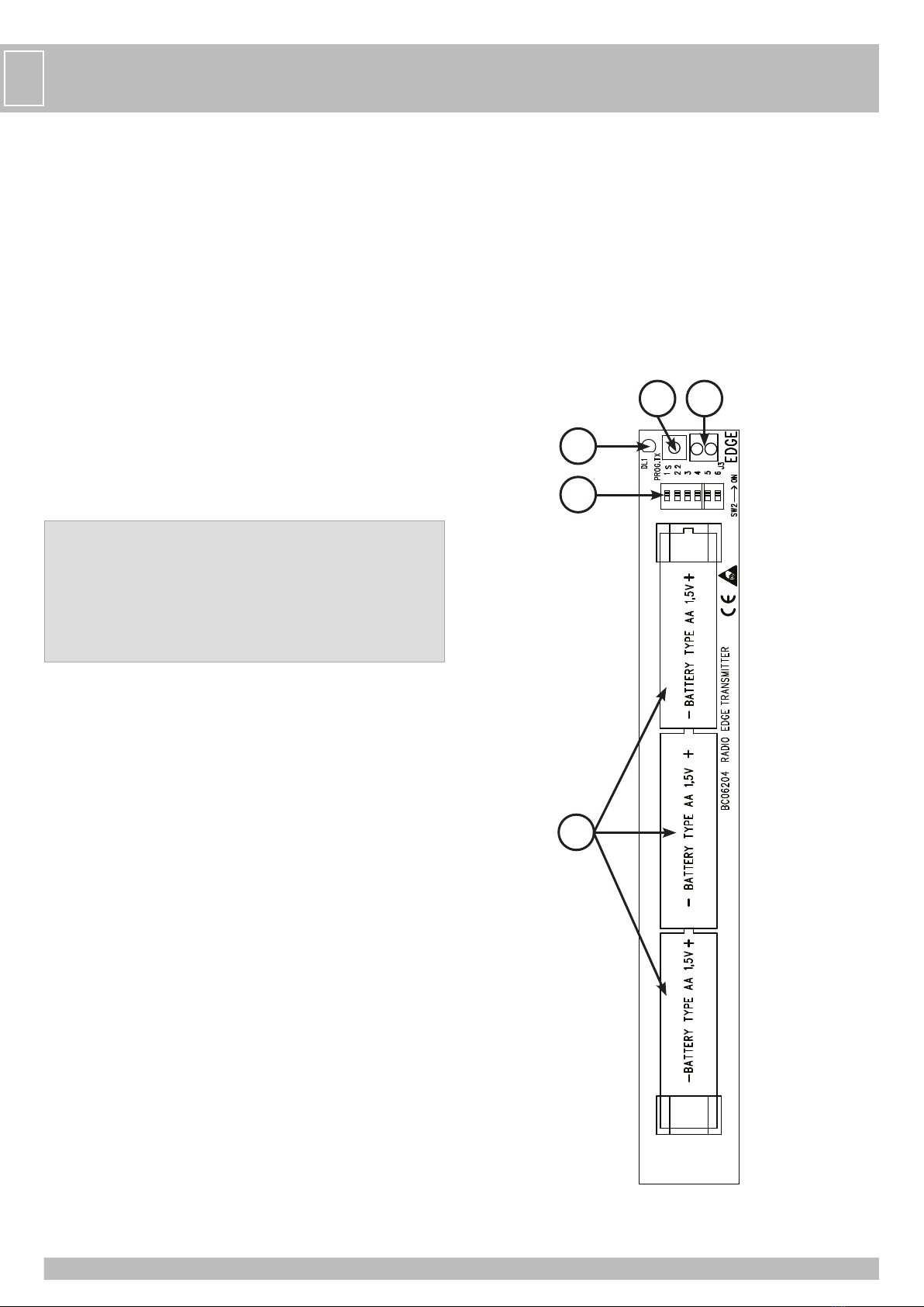
- Premere il tasto PROG. TX di TOUCH Wi-Fi con microinterruttore 2 su ON => su MASTER
Wi-Fi il led bicolore EDGE PHOT 2 da rosso lampeggiante diventa verde lampeggiante e un
tono di buzzer segnala la corretta memorizzazione di TOUCH Wi-Fi .
- Eseguire la stessa procedura per eventuali altre TOUCH Wi-Fi (fino ad un massimo di 6).
VERIFICA DEL CORRETTO FUNZIONAMENTO
Terminata la procedura di memorizzazione, verificare il corretto funzionamento tra TOUCH
Wi-Fi e MASTER Wi-Fi nel seguente modo:
- Verificare che premendo la costa TOUCH Wi-Fi con dip 1 ON, il corrispondente led bicolore
EDGE PHOT 1 sulla scheda MASTER Wi-Fi si accenda di colore verde per la durata della
pressione.
Anche il led DL2 si spegnerà indicando l’avvenuta interruzione del contatto dedicato
all’ingresso EDGE sul quadro di comando del motore.
- Ripetere la verifica per tutte le TOUCH Wi-Fi installate.
Eseguire una verifica funzionale di tutte le TOUCH Wi-Fi installate attivando la movimentazione
dell’automazione e controllando che all’impatto con la costa l’automazione fermi/inverta il
movimento.
IN CASO DI DIFFICOLTA’
SINTOMO VERIFICA
La costa non funziona Verificate lo stato delle batterie e del contatto
PER ALTRE INFORMAZIONI FATE RIFERIMENTO AL LIBRETTO ISTRUZIONI DELLA SCHEDA MASTER Wi-Fi
CARATTERISTICHE TECNICHE ELETTRONICHE
TOUCH Wi-Fi è certificata EN13849-2 2008 - ref. n. 10.027 - categoria 2
FREQUENZA 868,3 MHz
SENSIBILITA’ -108 dBm
POTENZA DI EMISSIONE <25 mW
ALIMENTAZIONE batterie 3 x AA 1,5 V (> 2,7 Ah)
ASSORBIMENTO A RIPOSO 25 µA
ASSORBIMENTO MASSIMO 13 mA
TIPO DI MODULAZIONE FSK
PORTATA 20 m in spazio libero senza antenna
VITA DELLA/E BATTERIE 3 anni (tipo AA)
PORTATA DEI CONTATTI 0,5 A - 24 V c.a. c.c.
TEMPERATURA DI LAVORO -20°C ÷ +60°C
GRADO DI PROTEZIONE IP44
GRADO DI UMIDITÀ RELATIVA <93%
CARATTERISTICHE TECNICHE MECCANICHE
CORSA DAL CONTATTO ALL’INTERVENTO (PRECORSA) max 15 mm
CORSA DALL’INTERVENTO ALLA BATTUTA MECCANICA (EXTRACORSA) min. 40 mm
TEMPO DI APERTURA DEI CONTATTI DALL’INTERVENTO max 0,1 s
TEMPO DI RECUPERO DALLA DEFORMAZIONE MASSIMA max 0,5 s
FORZA MASSIMA APPLICABILE AL DISPOSITIVO max 1 KN
MASSIMA VELOCITÀ DEL DISPOSITIVO IN MOVIMENTO max 0,25 m/s *
* L’utilizzo con operatori con velocità superiore a 0,25 m/s (15 m/min) determina un mancato rispetto
della normativa in vigore.
MANUTENZIONE PERIODICA
Deve essere effettuata solo da personale autorizzato in accordo con le regole di sicurezza e
con le istruzioni del fabbricante, con frequenza semestrale.
- La costa TOUCH Wi-Fi deve essere mantenuta in condizioni di lavoro efficienti e in accordo
con le istruzioni del fabbricante.
- Sostituire le batterie quando richiesto dal sistema (si veda tabella “in caso di difficoltà” su
manuale MASTER Wi-Fi).
- Verificare la presenza e la leggibilità della marcatura iniziale.
- Le parti usurabili sono segnalate nella tabella ”Tipologia di articoli per l’assemblaggio”;
eventuali sostituzioni devono essere eseguite da tecnico abilitato seguendo le istruzioni di
montaggio e verifica.
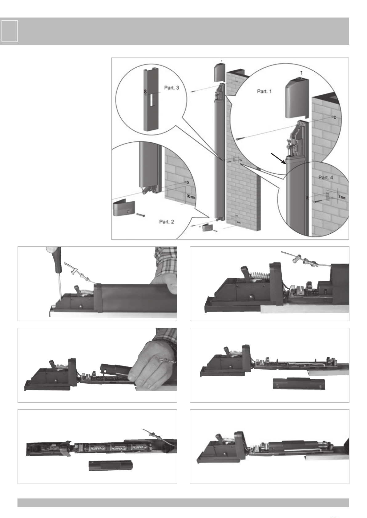
1 - Verificare che i coperchi (superiore e inferiore) e il supporto in alluminio siano integri e
non deformati; verificare che la parte in gomma sia integra e non lacerata.
2 - Smontare il coperchio.
3 - Controllare il cavo di acciaio che sia integro e non sfilacciato; sostituire il cavo in caso
contrario.
4 - Controllare che, in condizioni di riposo, la leva sia posizionata sul finecorsa centrale. In
caso contrario regolare la posizione agendo sulla vite di regolazione.
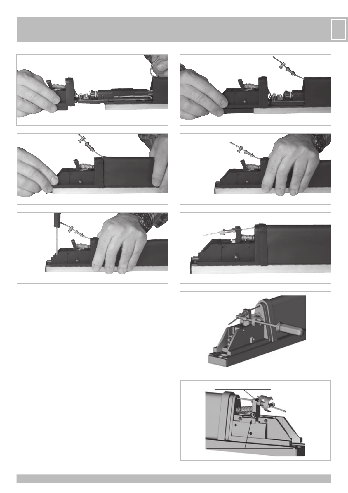
5 - Controllare l’integrità del coperchio superiore e sostituirlo se danneggiato.
6 - Verificare che non siano presenti tracce di umidità o corpi estranei e rimuoverli in caso
contrario.
7 - Tenendo premuto il contatto del finecorsa centrale, premere la gomma e controllare che
il circuito elettrico venga interrotto.
8 - Rilasciare il bordo di gomma e controllare che il contatto elettrico si ripristini.
9 - Rimontare il coperchio.
OPTIONAL
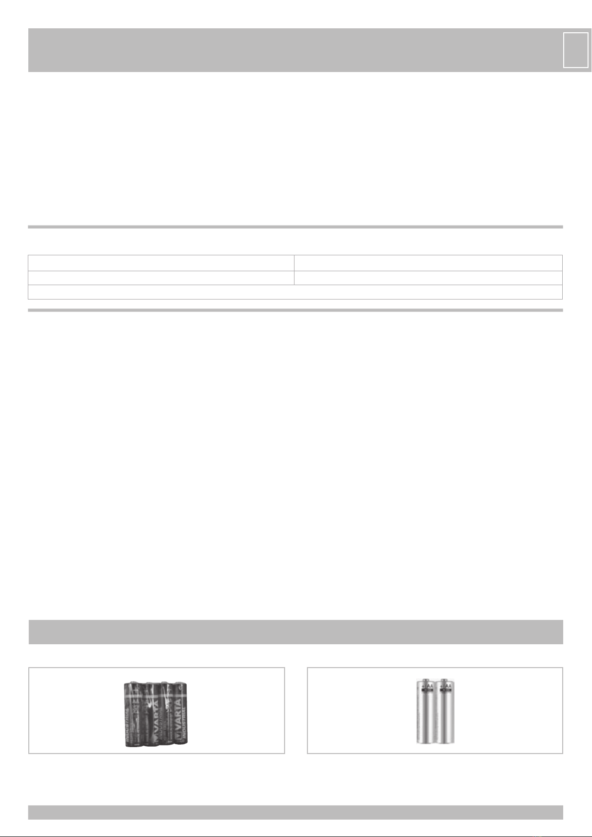
BATTERIE ALCALINE AA BATTERIE LITHIO AA
4 X 1,5V - con TOUCH Wi-Fi durata batterie 3 anni.
cod. ACG9519
2 X 1,5V - con TOUCH Wi-Fi durata batterie 4 anni (prendere 2 pezzi).
Per temperature estreme -40÷+60°C. cod. ACG9509

8
FCARACTERISTIQUES TECHNIQUES / INSTALLATION
TOUCH Wi-Fi est conforme à la norme EN13849-2 (2008) s’il est conjointement utilisé avec
MASTER Wi-Fi.
TOUCH Wi-Fi, s’il est utilisé avec un tableau électrique de la marque RIB, constitue un
dispositif de protection de classe 2. Son but est de protéger les personnes/objets d’un
quelconque choc qui proviendrait d’appareils mécaniques en mouvement comme des
portails ou des portes à fermeture automatique.
L’obstacleestdétectésurtoute la longueur du dispositif,parallèlementet perpendiculairement.
Les barres palpeuses TOUCH Wi-Fi peuvent être positionnées partout et ne nécessitent pas
l’utilisation de fils électriques.
Le système Wi-Fi (constitué de TOUCH Wi-Fi et de MASTER Wi-Fi) fonctionne à une
fréquence de 868,3 MHz.
La carte MASTER Wi-Fi est constamment en contact avec les barres palpeuses TOUCH Wi-Fi
et signale automatiquement les impacts ou dysfonctionnements éventuels.
Chaque TOUCH Wi-Fi possède un code d’identification interne unique qui le distingue des
autres dispositifs.
Le Système Wi-Fi constitue une sécurité active car il vérifie constamment le bon
fonctionnement des TOUCH Wi-Fi et l’état des piles.
Il est possible d’effectuer des contrôles automatiques du système en utilisant des tableaux
électriques RIB.
L’utilisation d’actionneurs RIB, de tableaux électriques RIB dotés de test automatique et
de sécurités RIB permet de réaliser une installation conforme aux normes et directives
européennes en vigueur.
Une fois l’installation terminée, il faut s’assurer qu’elle soit conforme à la norme EN13241-1.
RIB ne peut être tenu responsable d’éventuels dommages résultant d’une utilisation
impropre, inadéquate ou irresponsable du produit.
ATTENTION
Si vous avez enlevée l’alimentation du MASTER Wi-Fi pour une période de
temps rallongé, les barre palpeuse TOUCH Wi-Fi et les photocellules NOVA Wi-Fi
termineront plus rapidement du normal la charge de leurs batteries.
Gardez les MASTER Wi-Fi toujours correctement alimentés, pour garantir la durée
de 3 ans des batteries, comme déclarée de RIB.
Par exemple, si l’alimentation est coupée à la grille toutes les nuits, les
photocellules et les cordons “essaient” à plusieurs reprises sans trouver le signal
du MASTER Wi-Fi et l’autonomie des batteries de ces accessoires peut être
réduite à moins d’un an.
Des eventuelles modifications de produit ou de la configuration de l’appareil ne peuvent pas
être exécutées sans consulter le fabricant ou son représentant autorisé.
L’installateur du dispositif de sûreté doit fournir à l’utilisateur final tout ce qui suit:
- les dispositifs de sûreté doivent être connus de toutes les personnes appropriées;
- les aires qui donnent accès aux dispositifs doivent être tenues libres d’obstacles;
- les qualités pour le nottoyage à éviter eventuelles accumulations dangereuses de
matériel;
- possibles spécifications pour une procédure de renvoi à exécuter après une arrêtée
d’émergence ou accidentelle causée du système de contrôle.
La modification du projet ou de la configuration de l’appareil sans la consultation du fabricant
ou de son représentant autorisé peut créer des situations dangereuses.
RACCORDEMENTS ÉLECTRIQUES
BAT Piles alcalines 3 x 1,5 V (modèle AA code ACG9519)
SW2 Micro-interrupteurs de couplage et d’identification
J3 Pinces pour le raccordement de la barre palpeuse mécanique
S2 PROG TX Touche pour la programmation
DL1 (rouge) Signal de transmission radio
DL1
SW2
BAT
J3S2

9
F
1
TOU0001
TOU0002
TOU0003
TOU0021
TOU0020
TOU0007
TOU0008
TOU0009
TOU0011
TOU0010
Profile en caoutchouc,
disponible en paquets de
2 pièces, longueur m 7
Profile en aluminium,
disponible en barres de
m 2
Câble en acier
Groupe supérieur avec carte
électronique
Registre
Borne serre-câble en acier
Groupe inférieur
Couvercle inférieur
Vis pour couvercle inférieur
Couvercle inférieur avec vis
de fixation
Couvercle supérieur avec
vis de fixation
Accessoires pour le montage
du profile en aluminium
TYPOLOGIE DES ARTICLES POUR ASSEMBLAGE
L’installation du dispositif doit être effectuée par du personnel qualifié.
TOUCH Wi-Fi peut être installé seulement verticalement (comme en fig. 2 pag. 10) sur la
partie mobile et/ou sur la partie fixe.
Dans les deux cas, le but est d’éviter un écrasement/choc.
Les positions de fixation sont illustrées dans les exemples (fig. 1).
INSTRUCTIONS POUR LE MONTAGE
Positionnements possibles
Portail battant à deux vantaux Porte coulissante Portail coulissant

10
F
1 - Dévisser la vis de fixation de l’embout
supérieur et l’extraire (fig. 2 - 1 partie)
- Dévisser la vis de blocage de la partie
supérieure (fig. 3)
- Enlever la partie supérieure ainsi que la carte
électronique (fig. 4)
- Extraire le profilé en plastique (fig. 5-6)
- Insérer 3 piles alcalines de type AA de 1,5V
en faisant attention à la polarité (fig. 7).
- Insérer le profilé conducteur en plastique
dans l’emplacement réservé (fig. 8)
- Identifier et mémoriser la carte électronique
comme expliqué ci-après.
- Insérer la carte électronique et le groupe
mécanique dans le profilé en caoutchouc
(fig. 9-10-11).
- Insérer le câble en acier dans la fente
présente sur le groupe mécanique (fig. 12)
- Bloquer le groupe mécanique sur le profilé
en aluminium en utilisant la vis desserrée
précédemment (fig. 13)
- Insérer le câble d’acier dans la fente présente
sur le levier (fig. 14)
* Quand on a assemblé le bord, il faut
s’assurer qu’il n’y a pas d’ouvertures dans
le point indiqué. Le profil en gomme et
les parties au dessus doivent adhérer, afin
d’éviter des infiltrations d’eau ou d’insectes.
43
5 6
7 8
2
*

11
F
2 - Vérifier que la vis de la borne serre-câble en acier soit bien serrée (fig. 15).
3 - Contrôler que le levier fasse pression sur la butée centrale. Si ce n’est pas le cas,
desserrer le boulon de blocage du registre pour que la rondelle soit dans la bonne
position (fig. 16).
4 - Dévisser les vis de fixation de l’embout inférieur et l’enlever (fig.2 - part. 2).
5 - Marquer la position (S) du trait supérieur de la fente de fixation sur le côté du profilé
en aluminium (fig. 2 - part. 3)
6 - Positionner TOUCH Wi-Fi sur le mur et marquer l’emplacement correspondant à la
marque effectuée précédemment. Dans le montage vertical, maintenir une distance
minimale de 30 mm du sol en orientant le dispositif comme montré dans la figure
2 - part. 2.
7 - Percer le plan de support de la barre palpeuse environ 7 mm sous la marque et fixer
le ressort de retenue avec les éléments adéquats, tels que des vis à métaux ou un
assemblage vis/cheville pour maçonnerie (fig. 2 - part. 4)
8 - Positionner TOUCH Wi-Fi sur le ressort de retenue et l’accrocher en le tirant vers le
bas.
9 - Marquer les points de fixation sur le mur pour C et D (fig. 2 - part. 1 et 2)
10 - Ôter le dispositif et faire les trous pour la fixation, suivant les marquages effectués
précédemment.
11 - Accrocher de nouveau le dispositif sur le ressort et fixer les vis.
14
13
12
11
109
Ecrou de blocage registre
Position du rouleau sur la butée central 16
15

12
12 - Insérer l’embout inférieur dans l’emplacement et le fixer avec les vis (fig. 17).
13 - Insérer l’embout supérieur et le fixer avec la vis.
14 - Contrôler le fonctionnement du TOUCH-Wifi comme expliqué dans la section «
CONTROLE DU FONCTIONNEMENT »
MEMORISATION
Après avoir effectué l’identification des TOUCH Wi-Fi, basculer les micro-interrupteurs
correspondants sur ON sur le MASTER Wi-Fi et poursuivre avec la mémorisation des codes
des TOUCH Wi-Fi :
- Appuyer sur la touche PROG RX sur le MASTER Wi-Fi => La LED bicolore EDGE PHOT 1
clignotera rouge pendant 1 minute (le temps nécessaire pour effectuer la mémorisation).
- Appuyer sur la touche PROG TX sur le TOUCH Wi-Fi avec le micro-interrupteur 1 sur
ON => La LED bicolore EDGE PHOT 1 sur le MASTER Wi-Fi passe de rouge clignotant à
vert et un bip signale que la mémorisation a été correctement effectuée. Ensuite, la LED
bicolore EDGE PHOT 2 se met à clignoter rouge pendant 1 minute (le temps nécessaire
pour effectuer la mémorisation).
- Si d’autres TOUCH Wi-Fi ne doivent pas être mémorisées, attendre une minute et la LED
bicolore EDGE PHOT 2 s’éteindra ou appuyez 4 fois sur PROG RX pour finir le processus de
mémorisation => toutes les LED bicolores EDGE PHOT devraient s’éteindre.
Introduction
17
IDENTIFICATION
Chaque TOUCH Wi-Fi est livré avec les micro-interrupteurs en position OFF par défaut pour
éviter que les piles se déchargent quand il n’est pas utilisé (si celles-ci sont insérées).
Chaque TOUCH Wi-Fi doit OBLIGATOIREMENT être identifié de manière unique en
positionnant un seul des six micro-interrupteurs (SW2) sur ON.
Il ne faut positionner sur ON qu’un seul des 6 micro-interrupteurs et l’identification doit être
différente pour chaque TOUCH Wi-Fi.
Remarque: IDENTIFIER LES BOITIERS DES TOUCH Wi-Fi EN POSANT UNE ETIQUETTE
NUMÉROTÉE (FOURNIE) SUR CHAQUE BOITIER.
L’identification des boitiers est utile pour remplacer rapidement les piles déchargées de
TOUCH Wi-Fi. Leur décharge est indiquée par les LED de la carte MASTER Wi-Fi.
1 2 3 4 5 6
OFF
1 2 3 4 5 6
ON
EXEMPLE D’IDENTIFICATION D’UNE BARRE PALPEUSE
TOUCH Wi-Fi SUR MASTER Wi-Fi
EXEMPLE D’IDENTIFICATION
DE 3 BARRES PALPEUSES TOUCH Wi-Fi SUR MASTER Wi-Fi
ON ON
6
5
4
3
2
1
6
5
4
3
2
1
6
5
4
3
2
1
6
5
4
3
2
1
6
5
4
3
2
1
6
5
4
3
2
1
12/24V ac/dc
PROG RX LED BICOLORE 1
F
MASTER Wi-Fi MASTER Wi-Fi
TOUCH Wi-Fi 1 TOUCH Wi-Fi 1 TOUCH Wi-Fi 2 TOUCH Wi-Fi 3

13
POUR MÉMORISER D’AUTRES TOUCH Wi-Fi
- Appuyer sur le bouton PROG TX du TOUCH Wi-Fi avec le micro-interrupteur 2 sur ON =>
La LED bicolore EDGE PHOT 2 passe de rouge clignotant à vert clignotant sur le MASTER
Wi-Fi et un bip signale que la mémorisation du TOUCH Wi-Fi a été correctement effectuée.
- Effectuer la même procédure pour d’éventuels autres TOUCH Wi-Fi (au maximum 6).
CONTROLE DU FONCTIONNEMENT
Une fois que le processus de mémorisation est terminé, vérifier que le fonctionnement soit
correct entre le TOUCH Wifi et le MASTER Wifi de la manière suivante:
- Vérifier qu’en appuyant sur la barre palpeuse TOUCH Wi-Fi avec l’interrupteur 1 en position
ON, la LED bicolore correspondante EDGE PHOT 1 sur la carte MASTER Wi-Fi s’allume en
vert tant que l’on reste appuyé.
La LED DL2 s’éteindra pour signaler l’interruption du contact EDGE sur le tableau de
commande du moteur.
- Répéter la vérification pour tous les TOUCH Wi-Fi installés.
Faire un test de fonctionnement de tous les TOUCH Wi-Fi installés en activant le mouvement
de l’automatisme et en contrôlant que lors du contact avec la barre palpeuse, le mouvement
s’arrête/s’inverse.
EN CAS DE PROBLÈME
PROBLÈME VERIFICATION
La barre palpeuse ne fonctionne pas Vérifiez l’état des piles et du contact
POUR DE PLUS AMPLES INFORMATIONS, REFEREZ VOUS AU MANUEL D’INSTRUCTIONS DE LA CARTE MASTER Wi-Fi.
CARACTÉRISTIQUES TECHNIQUES ÉLECTRONIQUES
CERTIFIÉ EN 13849-2 (2008) N. 10.027 CATÉGORIE 2
FRÉQUENCE 868,3 MHz
SENSIBILITÉ -108 dBm
PUISSANCE D’ÉMISSION <25 mW
ALIMENTATION piles 3 x AA 1,5 V (>2,7 Ah)
CONSOMMATION EN VEILLE 25 µA
CONSOMMATION MAXIMALE 13 mA
TYPE DE MODULATION FSK
PORTÉE 20 m dans l’air sans antenne
DURÉE DE VIE DE LA/ DES PILE(S) 3 Ans (modèle AA)
PORTÉE DES CONTACTS 0,5 A - 24 V c.a. c.c.
TEMPÉRATURE DE FONCTIONNEMENT -20°C ÷ +60°C
DEGRÉ DE PROTECTION IP44
DEGRÉ D’ HUMIDITÉ RELATIVE <93%
CARACTÉRISTIQUES TECHNIQUES MÉCANIQUES
COURSE DU CONTACT A L’INTERVENTION (DEMARRAGE) max 15 mm
COURSE DE L’INTERVENTION A LA BUTÉE MÉCANIQUE (DEPASSEMENT) min. 40mm
DURÉE D’OUVERTURE DES CONTACTS A PARTIR DE L’INTERVENTION max 0,1 s
DURÉE DE RÉCUPÉRATION A PARTIR DE LA DÉFORMATION MAXIMALE max 0,5 s
FORCE MAXIMALE APPLICABLE SUR LE DISPOSITIF max 1 KN
VITESSE MAXIMALE DU DISPOSITIF EN MOUVEMENT max 0,25 m/s *
* L’utilisation avec des opérateurs possédant une vitesse supérieure à 0,25 m/s (15m/min) constitue un
non- respect des normes en vigueur.
ENTRETIEN RÉGULIER
Il doit être effectué seulement de personnel autorisé en accord avec les règles de sûreté et
avec les instructions du fabricant, avec la fréquence semestrielle.
- Le barre palpeuse TOUCH WI-Fi doit être maintenu en conditions de travail efficaces et en
accord avec les instructions du fabricant.
- Substituer les batteries lorsque demandé du système (voir tableau EN CAS DE DIFFICULTÉ
sur manuel MASTER Wi-Fi).
- Vérifier la présence et la lisibilité du marquage initial.
- Les parties à usure sont signalées dans le tableau “Typologie d’articles pour l’assemblage”;
les eventuelles substitutions doivent être exécutées du technicien certifié, en suivant les
instructions de montage et contrôle.
1 - Vérifier que les embouts (supérieur et inférieur) et le support en aluminium soient intacts
et non déformés; vérifier que la partie en caoutchouc ne soit ni abimée ou déchirée.
2 - Démonter l’embout
3 - Vérifier que le câble en acier soit intact. Si ce n’est pas le cas, le remplacer.
4 - En veille, vérifier que le levier soit positionné sur la butée centrale. Dans le cas contraire,
ajuster la position en agissant sur la vis de réglage.
5 - Vérifier que l’embout supérieur soit intact. Sinon le remplacer.
6 - Vérifier qu’il n’y ait pas de trace d’humidité ou de corps étranger. Les enlever s’il y en a.
7 - En maintenant appuyé le contact de la butée centrale, presser le caoutchouc et vérifier
que le circuit électrique soit interrompu.
8 - Relâcher la barre palpeuse et vérifier que le contact électrique soit rétabli.
9 - Remettre l’embout.
F
OPTIONS
BATTERIES ALCALINES AA BATTERIES LITHIO AA
4 X 1,5V - avec TOUCH Wi-Fi vie batteries 3 ans.
code ACG9519
2 X 1,5V - avec TOUCH Wi-Fi vie batteries 4 ans (prendre 2 pièces).
Pour des températures extrêmes -40÷+60°C. code ACG9509

14
G
BTECHNICAL DATA / INSTALLATION
TOUCH Wi-Fi in combination with the electronic device MASTER Wi-Fi conforms to standard
EN13849-2 (2008) and when used with a RIB electronic control panel it is a Class 2
protection device for protecting persons/things from collisions caused by mechanical moving
parts such as automatic gates or doors. The obstacle is detected along the entire length of
the device axially and perpendicularly.
The TOUCH Wi-Fi strips can be positioned anywhere without needing to use electrical wire.
The WiFi system (made up of a TOUCH Wi-Fi and MASTER Wi-Fi) operate at a frequency
of 868,3 MHz.
The MASTER Wi-Fi card communicates constantly with the TOUCH Wi-Fi strips and always
signals collisions or malfunctions.
Each TOUCH Wi-Fi has its own internal ID code that distinguishes it from the other devices.
The WiFi system is an active security system because it constantly verifies proper functioning
of the TOUCH Wi-Fi devices and battery condition.
When using RIB electronic control panels you can run auto-tests on the system.
With RIB actuators, RIB electronic control panels having the auto-test function and RIB
safety devices you can create an installation that conforms to the European Directives and
Norms in force.
After completing the system, you must make sure it conforms to standard EN13241-1.
RIB shall not be liable for any damages caused by improper, incorrect or unreasonable use
of the product.
ATTENTION:
If you remove the power of the MASTER Wi-Fi for a long time, the TOUCH Wi-Fi
safety strips and the NOVA Wi-Fi photocells will exhaust faster than normal the
charging of their batteries. Keep the MASTER Wi-Fi always properly fed to ensure
a period of three years for the batteries-life, as stated by RIB.
If for instance, the power to the system is cut off every night, the photocells
and the safety strips will regularly and constantly search for the MASTER Wi-Fi
without finding it. Therefore, the life span of the batteries may be reduce to less
than one year.
Any possible modification of the device, or of the configuration of the same cannot be carried
out without the clear authorization by the manufacturer or, by the local authorized dealer.
The installer of the safety device must make sure that the end user know the following:
- That the safety devices must be made known to all appropriate people.
- That the passages to reach the devices must be kept clear from any obtsacle.
- About the procedures for cleaning so to avoid the dangerous building up of material.
- The possible details for a restart of the system after an emergency or accidental stop
caused by the control system.
Any modification of the project or, of the configuration of the device, without discussing it
first with the manufacturer or with the local autorized dealer can cause dangerous situations.
ELECTRICAL CONNECTIONS
BAT Alkaline batteries 3 x 1.5V (type AA code ACG9519)
SW2 Microswitches for combination and identification
J3 Terminals for connecting to mechanical strip contact
S2 PROG. TX Programming pushbutton
DL1 (red) Radio transmission signal
DL1
SW2
BAT
J3S2

15
G
B
1
TOU0001
TOU0002
TOU0003
TOU0021
TOU0020
TOU0007
TOU0008
TOU0009
TOU0011
TOU0010
Rubber profile available
in packages of n° 2 items
7 m length
Aluminium profile available
in strips from 2 m
Steel cable
Upper assembly with electronic board
Register
Steel flat connector
Lower group
Lower cover
Screws for lower cover
Lower cover with fastening
screws
Upper cover with fastening
screws
Accessories for assembling
Aluminium profile
TYPE OF ITEMS FOR ASSEMBLY
The device must be assembled by qualified people trained specifically for this purpose.
TOUCH Wi-Fi can be mounted only vertically (as per pitc. 2 page 16) on the moving
part and/or the fixed part. In both cases the purpose is to avoid crushing/collision.
The fastening positions are shown in the examples in Fig. 1.
ASSEMBLY INSTRUCTIONS
Possible positions
Double leaf swing gate systems Sliding door systems Sliding gate systems

16
G
B
1 - Unscrew fastening screws of upper cover and
remove it (fig. 2 - part. 1).
- Unscrew gland bolts from upper part (fig. 3).
- Remove upper part complete with the adjacent
electronic board(fig. 4).
- Remove plastic guide from notches (fig. 5-6).
- Insert 3 alkaline type AA with batteries 1.5V
and pay attention to the polarities (fig. 7).
- Insert plastic guide into notches fig. 8).
- Identify and memorize electronic board as
indicated below.
- Insert electronic card with mechanical
assembly into rubber profile (fig. 9-10-11).
- Insert steel cable into appropriate slot on
mechanical assembly (fig. 12).
- Lock mechanical assembly to aluminum profile
using screws loosened previously (fig. 13).
- Insert steel cable into slot located on lever (fig.
14).
* Once the safety edge is fixed, make sure
there are no gaps in between the parts
indicated.The rubber profile and the parts
above it, must perfectly adhere to avoid the
passage of rain or insects.
43
5 6
7 8
2
*

17
G
B
2 - Make sure screw on steel cable clamp is tightened securely using force (fig. 15).
3 - Make sure lever presses the central limit switch. If it does not, loosen locknut that
locks the adjuster and regulate the adjuster until the castor reaches the proper position
(fig. 16).
4 - Unscrew fastening screws of lower cover and remove it (fig. 2 - part. 2).
5 - Marks position (S) on upper side of fastening slot on the side of the aluminum bar (fig.
2 - part. 3).
6 - Position TOUCH Wi-Fi on the wall and mark the position corresponding to the reference
marked previously. In cases of vertical assembly, keep a minimum distance from the
ground of 30 mm and aim the device as shown in fig. 2 - part. 2.
7 - Perforate strip support surface about 7 mm under reference mark and fasten retention
spring with appropriate elements: screws for metal or screws and anchor bolts for
masonry (fig. 2 - part. 4).
8 - Position TOUCH Wi-Fi on retention spring and hook it by pulling it downward.
9 - Mark fastening holes on wall in correspondence to -C- and -D- (fig. 2 - part 1 and 2).
10 - Remove device and drill fastening holes marked previously.
11 - Hook device to spring again and tighten screws.
14
13
12
11
109
Regulation check nut
Position the roller on central micro-switch pin 16
15

18
G
B
12 - Insert lower cover into notch and fasten with screws (fig. 17).
13 - Insert upper cover and fasten with screws.
14 - Check functioning of TOUCH Wi-Fi as described under the paragraph of “CHECK
PROPER FUNCTIONING”.
MEMORIZATION
After identifying the TOUCH Wi-Fi, put the microswitches corresponding to the MASTER
Wi-Fi in the ON position and memorize the codes of the TOUCH Wi-Fi:
- Press the PROG RX key located on the MASTER Wi-Fi=> the bicolor EDGE PHOT 1 LED will
flash red for one minute (the time needed to execute memorization).
- Press the PROG TX key on the TOUCH Wi-Fi with microswitches 1 set to ON => on the
MASTER Wi-Fi the bicolor EDGE PHOT 1 LED flashing red will become green and a buzzer
will signal that memorization of the TOUCH Wi-Fi is correct, after which the bicolor EDGE
PHOT 2 LED immediately starts flashing red for one minute (time needed to execute
memorization) l.
- If other TOUCH Wi-Fi are not memorized, let one minute pass and the bicolor EDGE PHOT
2 LED turns off; or press the PROG. RX key four times to end the memorization procedure
=> all bicolor EDGE PHOT LEDs must be off.
Insertion
17
IDENTIFICATION
Each TOUCH Wi-Fi is supplied with microswitches in the OFF position to prevent batteries
from becoming discharged when not in use (if connected).
Each TOUCH Wi-Fi must be ABSOLUTELY unequivocally identified by putting only one of
the six microswitches in the ON position (SW2).
Only one of the six microswitches must be in the ON position and the identification must be
different for each TOUCH Wi-Fi.
Note: IDENTIFY TOUCH Wi-Fi CONTAINERS BY APPLYING NUMBERED ADHESIVE LABEL
(SUPPLIED) ON OUTSIDE OF EACH CONTAINER.
Identification of containers serves to rapidly replace dead batteries in TOUCH Wi-Fi indicated
by EDGE LED on MASTER Wi-Fi card.
1 2 3 4 5 6
OFF
1 2 3 4 5 6
ON
EXAMPLE OF IDENTIFICATION OF A TOUCH Wi-Fi
STRIP ON A MASTER Wi-Fi EXAMPLE OF IDENTIFICATION OF 3 TOUCH Wi-Fi STRIPS
ON A MASTER Wi-Fi
ON ON
6
5
4
3
2
1
6
5
4
3
2
1
6
5
4
3
2
1
6
5
4
3
2
1
6
5
4
3
2
1
6
5
4
3
2
1
12/24V ac/dc
PROG RX BICOLOR LED 1
MASTER Wi-Fi MASTER Wi-Fi
TOUCH Wi-Fi 1 TOUCH Wi-Fi 1 TOUCH Wi-Fi 2 TOUCH Wi-Fi 3

19
G
B
TO MEMORIZE OTHER TOUCH Wi-Fi
- Press the PROG. TX key of the TOUCH Wi-Fi with microswitch 2 turned ON => on MASTER
Wi-Fi the bicolor EDGE PHOT 2 LED turns from flashing red to flashing green and a buzzer
tone sounds to indicate proper memorization of the TOUCH Wi-Fi .
- Perform the same procedure for any other TOUCH Wi-Fi (up to a maximum of 6).
CHECKING PROPER FUNCTIONING
After the memorization procedure, check proper functioning between the TOUCH Wi-Fi and
the MASTER Wi-Fi as follows:
- Make sure that when you press the TOUCH Wi-Fi strip with dip 1 ON, the corresponding
bicolor EDGE PHOT 1 LED on the MASTER Wi-Fi Board turns red for the duration of the
pressing action.
The DL2 LED will turn off to indicate interruption of the contact dedicated to the EDGE input
on the motor control panel.
- Repeat the check on all the installed TOUCH Wi-Fi.
Run a functional check on all the installed TOUCH Wi-Fi by activating the motion of the
automation and check that, upon collision with the strip, the automation stops/inverts its
motion.
IN CASES OF DIFFICULTY
PROBLEM CHECK
The strip does not work Check condition of batteries and contact
FOR OTHER INFORMATION REFER TO THE INSTRUCTION BOOKLET OF THE MASTER Wi-Fi CARD
ELECTRONIC TECHNICAL CHARACTERISTICS
CERTIFIED EN 13849-2 (2008) NO. 10.027 CATEGORY 2
FREQUENCY 868,3 MHz
SENSITIVITY -108 dBm
OUTPUT POWER <25 mW
POWER SUPPLY 3 type AA batteries 1.5 V (> 2.7 Ah)
INPUT AT REST 25 µA
MAXIMUM INPUT 13 mA
MODULATION TYPE FSK
CAPACITY 20 m in free space without antenna
BATTERY LIFE 3 years (type AA)
CAPACITY OF CONTACTS 0,5 A - 24 V c.a. c.c.
WORKING TEMPERATURE -20°C ÷ +60°C
DEGREE OF PROTECTION IP44
DEGREE OF RELATIVE HUMIDITY <93%
TECHNICAL MECHANICAL CHARACTERISTICS
STROKE FROM CONTACT TO INTERVENTION (PRE-STROKE) max 15 mm
STROKE FROM INTERVENTION TO MECHANICAL STRIKER PLATE (BEYOND STROKE)
min. 40 mm
OPENING TIME OF CONTACTS AFTER INTERVENTION max 0.1 s
RECOVERY TIME OF MAXIMUM DEFORMATION max 0.5 S
MAXIMUM FORCE APPLICABLE TO THE DEVICE max 1 KN
MAXIMUM SPEED OF DEVICE IN MOTION max 0.25 M/S *
* Using with operators at a speed greater than 0.25 m/s (15 m/min) is a breach of regulatory provisions.
ROUTINE MAINTENANCE
Must be carried out every six months, only by authorized personnel in agreement with the
safety rules and with the manufacturer’s instructions.
- The TOUCH Wi-Fi safety edge must be kept in efficient working conditions and in
agreement with the manufacturer’s instructions.
- Replace the batteries when requested by the system (see the chart “IN CASE OF
DIFFICULTIES” on the MASTER Wi-Fi manual).
- Verify the presence and the possibility to read the initial marking.
- The parts that wear off are mentioned in the chart ”Type of items for the assembly”;
eventual replacements must be carried out by an authorized technician, following the
assembly instructions and verification.
1 - Make sure covers (upper and lower ) and aluminum support are in good condition and not
bent out of shape; make sure rubber part is in good condition and not torn.
2 - Dismantle cover.
3 - Check steel cable to make sure it is in good condition and not frayed; replace cable is
necessary.
4 - Make sure that in conditions of rest, the lever is positioned on the central limit switch. If
it is not, regulate the position by turning the adjustment screws.
5 - Check condition of upper cover and replace it if it is damaged.
6 - Make sure there are no traces of moisture or foreign bodies and remove them if there
are any.
7 - Keeping the contact of the central limit switch pressed, press the rubber and make sure
the electric circuit is interrupted.
8 - Release rubber strip and make sure electric contact resets.
9 - Put cover back on.
ACCESSORIES
AA ALKALINE BATTERIES AA LITHIO BATTERIES
4 X 1,5V - battery life with TOUCH Wi-Fi 3 years.
code ACG9519
2 X 1,5V - battery life with TOUCH Wi-Fi 4 years (buy 2 pieces).
For extreme temperatures -40÷+60°C. code ACG9509

20
TOUCH Wi-Fi in Kombination mit dem Elektronikgerät MASTER Wi-Fi erfüllt die DIN
EN13849-2 (2008) und bei Benutzung mit der elektronischen Schalttafel von RIB wird es
zu einem Gerät der Schutzklasse 2 zum Schutz von Personen/Gegenständen, mit denen
bewegende Teile von automatischen Toren oder Türen kollidieren können. Das Hindernis wird
über die gesamte Länge parallel zur Achse als auch senkrecht erkannt.
Die TOUCH Wi-Fi Kontaktleiste kann überall montiert werden, ohne dass ein elektrisches
Kabel erforderlich ist. Das WiFi-System (bestehend aus einem TOUCH Wi-Fi und MASTER
Wi-Fi) arbeitet mit einer Frequenz von 868,3 MHz.
Die MASTER Wi-Fi Karte kommuniziert ununterbrochen mit der TOUCH Wi-Fi Kontaktleiste
und signalisiert alle Kollisionen oder Fehlfunktionen.
Zur Unterscheidung eines Gerätes von einem anderen verfügt jeder TOUCH Wi-Fi über
seinen eigenen internen Erkennungscode.
Das WiFi-System ist ein aktives Sicherheitssystem, da es ununterbrochen die korrekte
Funktion der TOUCH Wi-Fi Geräte und ihren Batteriezustand überprüft.
Mit der elektronischen Schalttafel von RIB können Sie automatische Systemtests durchführen.
Bei RIB-Antrieben verfügen die elektronischen Schalttafeln von RIB über die Funktion zur
Durchführung automatischer Systemtests und mit RIB-Sicherheitsgeräten können Sie die
Installation gemäß geltenden Europäischen Richtlinien und Normen ausführen.
Nach der Installation des Systems müssen Sie sicherstellen, dass es die Norm EN 13241-1
erfüllt.
RIB haftet nicht für Schäden jeglicher Art, die sich auf unsachgemäße, falsche oder
unangemessene Verwendung der Produkte zurückführen lassen.
VORSICHT:
Wenn die Speisung des MASTER Wi-Fi für eine lange Zeit entfernt wird, leeren
die Kontaktleisten TOUCH Wi-Fi und die Fotozellen NOVA Wi-Fi schneller als
die normale Aufladung ihrer Batterien. Halten die MASTER Wi-Fi immer richtig
ernährt, die Batterien sorgen für einen Zeitraum von drei Jahren, als von RIB
angegeben ist.
Zum Beispiel, wenn die Speisung am Tor, jede Nacht, entfernt wird, “versuchen”
Fotozellen und Kontaktleisten wiederholt, ohne Befund, das Signal vom MASTER
Wi-Fi und dann die Lebensdauer der Batterien dieser Zubehörteile auf weniger als
ein Jahr reduziert werden kann.
Man kann nicht Änderungen am Produkt oder Gerät-Konfiguration ohne Rücksprache mit
dem Hersteller oder seinem Bevollmächtigten erfolgen.
Der Installer der Sicherheitseinrichtung muss dem Endbenutzer liefern, wie folgt:
- Sicherheitseinrichtungen müssen bekannt gemacht, alle geeigneten Personen sein.
- Gebiete, die den Zugang zu Geräten sollten frei von Hindernissen gehalten werden;
- Anforderungen an die Reinigung keine Ansammlung von gefährlichen Stoffen zu verhindern;
- Mögliche Einzelheiten für einen Wiederaufnahme-Verfahren nach einem Stopp in einem
Notfall oder Unfall durch das Steuersystem verursacht ausgeführt werden.
Ändern Sie das Design oder die Konfiguration der Geräte ohne Rücksprache mit dem
Hersteller oder sein Bevollmächtigter können zu gefährlichen Situationen führen.
ELEKTRISCHE ANSCHLÜSSE
BAT Alkaline-Batterien 3 x AA 1,5V (Kode ACG9519)
SW2 Dip-Schalter für Kombination und Identifizierung
J3 Stecker für Anschluss der mechanischen Kontaktleiste
S2 PROG. TX Programmier-Drucktaste
DL1 (rot) Funkübertragungssignal
DL1
SW2
BAT
J3S2
DANLAGEN LAY-OUT
This manual suits for next models
1
Table of contents
Languages:
Other RIB Door Opening System manuals
Popular Door Opening System manuals by other brands

Sargent
Sargent ASSA ABLOY 8800 Series installation instructions

Dorma
Dorma ES 200 Easy Mounting instruction

Assa Abloy
Assa Abloy Effeff 843G Installation and mounting instructions

Lamp
Lamp FD50-H installation manual

IKEA
IKEA UTRUSTA installation instructions

CornellCookson
CornellCookson SGH 50023E Installation instructions and operation manual