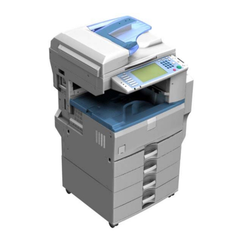
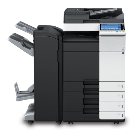
Ricoh FT4215 User manual

A128 COPIER
SERVICE MANUAL
Only the differrences from the A110/A111 copier are described in
the following pages. Refer to the A110/A111 copier service manual
regarding the other information.

1. SPECIFICATIONS
Configuration: Desk top
Copy Process: Dry electrostatic transfer system
Originals: Sheet/Book, object
Original Size: Maximum: A3, 11" x 17"
Copy Paper Size: Maximum: A3, 11" x 17"
Minimum: A6, 51/2" x 81/2" (lengthwise)
Copy Paper Weight: 52 to 157 g/m2(14 to 42 lb)
Reproduction Ratios: 2 Enlargement and 3 Reduction
A4/A3 version LT/LDG version
Enlargement 141%
122% 155%
129%
Full size 100% 100%
Reduction 93%
82%
71%
93%
74%
65%
Zoom: From 50% to 200% in 1% steps
Copying Speed: 15 copies/minute (A4, 11" x 81/2" sideways)
10 copies/minute (A3, 11" x 17")
Warm-Up Time: Less than 60 seconds (at 20°C)
First Copy Time: 5.9 seconds (A4, 11" x 81/2" sideways for cassette
feed)
Copy Number Input: Ten keys, 1 to 99 (count up)
Manual Image Density
Selection: 7 steps
Automatic Reset: All input modes are reset 1 minute after the copier
is not in use; can also be set to 3 minutes or no
auto reset.
31 March 1994 SPECIFICATIONS
1

Energy Saver Function: Reduces electricity consumption
(Manual or manual/auto)
Paper Capacity: Cassettes: 500 sheets (A4, 81/2" x 11")
250 sheets (A3, 11" x 17")
Manual feed table: 50 sheets
Toner Replenishment: Black: Cartridge exchange (370g/cartridge)
Color (red, blue, & green):
Cartridge exchange (310 g/cartridge)
Copy Tray Capacity: 250 sheets (B4, 81/2" x 14" and smaller)
100 sheets (A3, 11" x 17")
Power Source: 110 V/ 60 Hz/ 15 A (for Taiwan)
115 V/ 60 Hz/ 15 A (for North America)
220/230/240 V/ 50 Hz/ 8 A (for Europe)
220 V/ 60 Hz/ 8 A (for Middle East)
(Refer to the serial number plate (rating plate) to
determine the power source required by the
machine.)
Power Consumption:
Copier Only Full System
Maximum 1.2 KVA 1.5 KVA
Warm-up 800 VA (average) 800 VA (average)
Copy cycle 900 VA (average) 800 VA (average)
Stand-by
(without energy
saver function)
180 VA (average) 180 VA (average)
Main switch off 20 VA (average) 40 VA (average)*
* : With the optional optics anti-condensation heater
SPECIFICATIONS 31 March 1994
2

Dimensions:
Width Depth Height
Copier only 672 mm (1130 mm)*
(1255 mm)**
26.5" (44.5")*
(49.4")**
600 mm
23.7" 363 mm (417 mm)*
14.1" (16.4")*
Full system 1274 mm
49.1" 600 mm
23.7" 466 mm
18.3"
( )* : When the A4 cassette and platen cover are installed and the copy tray is
extended.
( )** : When the A3, 11" X 17" cassette and platen cover are installed and the copy
tray is extended.
Full system: When the A3, 11" x 17" cassette and the sorter and the document feeder are
installed.
Noise Emissions:
Maximum Copy cycle Stand-by
Copier only less than 58 dB less than 55 dB less than 40 dB
Full system less than 60 dB less than 58 dB less than 40 dB
Weight:
Copier only 50 kg (110.2 lb)
Full system 67 kg (147.7 lb)
Optional Equipment and Machine Configuration: ( ) Machine Code
Configuration Optional dc power supply unit (A525)
Optional equipment Required Not required
10 bin sorter (A490) O
Document feeder (A318) O
Color development unit (A313) O
Other Optional Equipment:• Key counter
• Universal cassette
• Optics anti-condensation heater
•Specifications are subject to change without notice.
31 March 1994 SPECIFICATIONS
3

2. COPY PROCESSES AROUND THE DRUM
CLEANING
The cleaning blade removes any toner remaining on the drum. (A cleaning
brush is not used in the A128 copier).
4. DEVELOPMENT
5. PRE-TRANSFER LAMP
6. IMAGE TRANSFER
7. PAPER
3. ERASE
2. EXPOSURE
1. DRUM CHARGE
9. QUENCHING
8. CLEANING
SEPARATION
(PTL)
COPY PROCESSES AROUND THE DRUM 31 March 1994
4

3. MECHANICAL COMPONENT LAYOUT
1 2 3 4 5 6 7 8 9 10 11 12 13 14
15
16
17
18
1924
2526
27
28
2023 2122
29
1. Third Mirror
2. Second Mirror
3. First Mirror
4. Exposure Lamp
5. Ozone Filter
6. Cleaning Unit
7. Lens
8. Quenching Lamp (QL)
9. Charge Corona Unit
10. Sixth Mirror
11. Erase Lamp
12. OPC Drum
13. Development Unit
14. Toner Supply Unit
15. Optics Cooling Fan
16. 1st Feed Roller
17. Manual Feed Table
18. Pick-up Roller
19. Separation Roller
20. Registration Rollers
21. Pre-transfer Lamp (PTL)
22. Transfer and Separation Corona Unit
23. Pick-off Pawls
24. Cleaning Blade
25. Pressure Roller
26. Hot Roller
27. Exit Rollers
28. Hot Roller Strippers
29. Exhaust Blower
31 March 1994 MECHANICAL COMPONENT LAYOUT
5

4. DRIVE LAYOUT
G17 BP2 G16 TB1 G19 G18 G22 G23 G24
G26
G27
G28
G29
G25
G21
G20G1
G2
G5
G6
G7
G9
G8
G10
G4 BP3 G3
BP1
G11
G1: Main Motor Gear G20: Relay Gear
TB1: Timing Belt G24: Relay Gear
G23: Relay Gear
Development
Section
Drum Fusing and Exit Section
BP1: Timing Belt Pulley
G2: Relay Gear G18: Relay Gear G21: Cleaning Drive
Cleaning
Toner Supply CL Toner Supply Unit
G17: Toner Supply CL Gear
Development UnitDevelopment CL Solenoid
G28: Exit Roller Gear
G16: Development
CLGear G27: Relay Gear
G26: Relay Gear
BP2: Timing Belt Pulley G25: Hot Roller Gear
A
G22: Relay GearG19: Drum Drive GearG3: Timing Belt Drive
Gear
DRIVE LAYOUT 31 March 1994
6

Paper Feed Section
BP3: Timing Belt Pulley
G11: Registration CL
Gear G4: Relay Gear
Registration CL G5: Relay Gear
Registration Roller
Paper Feed CL G6: 1st Paper Feed CL Gear
Paper Feed Gear G7: Relay Gear
Paper Feed Rollers G8: Paper Lift CL Gear
Paper Lift CL
G9: Paper Lift Gear
G10: Sector Gear
A
31 March 1994 DRIVE LAYOUT
7

5. ELECTRICAL COMPONENT LAYOUT
1
2
3
4
5678
9
10
11
12
13
14
15
16
17
18
19
20
21
22
23
24
25
26
27 28 29 30 31
1. Scanner H.P. Sensor
2. Lens H.P. Sensor
3. Scanner Motor
4. Main Motor
5. Development Clutch Solenoid
6. Toner Supply Clutch
7. 4th/5th Mirror H.P. Sensor
8. Color Toner End Sensor
9. 4th/5th Mirror Motor
10. Pick-up Roller Release Solenoid
11. Manual Feed Table Switch
12. Color Switch
13. Paper Lift Clutch
14. Paper Feed Clutch Solenoid
15. Registration Clutch
16. Paper Size Switch
17. Paper End Sensor
18. Paper Lift Sensor
19. Registration Sensor
20. Total Counter
21. Pre-transfer Lamp (PTL)
22. ID Sensor Board
23. Erase Lamp
24. Fusing Lamp
25. Quenching Lamp (QL)
26. Auto Image Density Sensor
27. Fusing Thermistor
28. Toner Overflow Sensor
29. Fusing Thermofuse
30. Exit Sensor
31. Lens Motor
ELECTRICAL COMPONENT LAYOUT 31 March 1994
8

36
37
38
39
40
41
42
43
44
45
46
47 48
35
34
33
32
32. Operation Panel Board
33. Optics Thermoswitch
34. Exposure Lamp
35. Cover Safety Switch
36. Main Switch
37. Exhaust Blower Motor
38. Drum Anti-condensation Heater
39. Main DC Power Supply Board
40. Option DC Power Supply Board
41. Option Transformer
42. Main Transformer
43. AC Drive Board
44. Main Motor Capacitor
45. Main Board
46. TC/SC Power Pack
47. CC/Grid/Bias Power Pack
48. Optics Cooling Fan Motor
31 March 1994 ELECTRICAL COMPONENT LAYOUT
9

6. ELECTRICAL COMPONENT DESCRIPTIONS
Symbol Name Function Index No.
Motors
M1 Main Motor Drives all the main unit components except
for the optics unit and fans.
(115/220/230/240 Vac)
4
M2 Scanner Motor Drives the scanners (1st and 2nd). (dc
stepper) 3
M3 Lens Motor Positions the lens according to the selected
magnification. (dc stepper) 31
M4 4th/5th Mirror Motor Positions the 4th/5th mirror according to the
selected magnification. (dc stepper) 9
M5 Optics Cooling Fan
Motor Prevents built up of hot air in the optics
cavity. (24 Vdc) 48
M7 Exhaust Blower
Motor Removes heat from around the fusing unit
and blows the ozone built up around the
charge section to the ozone filter.
(115/220/230/240 Vac)
37
Magnetic Clutch
MC1 Toner Supply Clutch Drives the toner supply roller. 6
Magnetic Spring Clutches
MSC2 Paper Lift Clutch Lifts paper to the appropriate feed station. 13
MSC3 Registration Clutch Drives the registration rollers. 15
Solenoids
SOL1 Paper Feed Clutch
Solenoid Starts paper feed from the first paper station. 14
SOL2 Pick-up Roller
Release Solenoid a) After a sheet of paper is fed, releases the
pick-up roller from next sheet.
b) When the manual feed table is used,
releases the pick-up roller from the table.
10
SOL3 Development
Clutch Solenoid Drives the development unit. 5
Switches
SW1 Main Switch Supplies power to the copier. 36
SW2 Cover Safety Switch Cuts the ac power line when the front cover
or/and exit cover is open. 35
SW3 Paper Size Switch Determines what size paper is in the
cassette. 16
SW6 Color Switch Determines which color development unit is
installed. 12
SW7 Manual Feed Table
Switch Detects when the manual feed table is open. 11
ELECTRICAL COMPONENT DESCRIPTIONS 31 March 1994
10

Symbol Name Function Index No.
Sensors
S1 Scanner Home
Position Sensor Informs the CPU when the 1st scanner is at
the home position. 1
S2 Lens Home
Position Sensor Informs the CPU when the lens is at the
home position (full size position). 2
S3 4th/5th Mirror Home
Position Sensor Informs the CPU when the 4th/5th mirror
assembly is at the home position (full size
position).
7
S4 Registration Sensor Detects misfeeds. 19
S5 Exit Sensor Detects misfeeds. 30
S6 Paper End Sensor Informs CPU when the cassette runs out of
paper. 17
S8 Color Toner End
Sensor Detects when it is time to add toner for the
color development unit. 8
S9 Paper Lift Sensor Detects the correct feed height of paper in
the cassette. 18
S10 Image Density (ID)
Sensor Detects the density of the image on the
drum to control the toner density. 22
S11 Auto Image Density
Sensor (ADS) Senses the background density of the
original. 26
S17 Toner Overflow
Sensor Detects when the used toner tank is full. 28
Printed Circuit Boards
PCB1 Main Board Controls all copier functions both directly
and through the other PCBs. 45
PCB2 AC Drive Board Drives all ac motors, the exposure lamp,
fusing lamp, quenching lamp, and exhaust
blower motor.
43
PCB3 Main DC Power
Supply Board Rectifies 28 Vac input and outputs dc
voltages. 39
PCB4 Operation Panel
Board Informs the CPU of the selected modes and
displays the situations on the panel. 32
PCB5 Option DC Power
Supply Board Rectifies 26 and 10 Vac input and outputs
dc voltages. This board is required when the
document feeder is installed.
40
Lamps
L1 Exposure Lamp Applies high intensity light to the original for
exposure. 34
L2 Fusing Lamp Provides heat to the hot roller. 24
L3 Quenching Lamp Neutralizes any charge remaining on the
drum surface after cleaning. 25
31 March 1994 ELECTRICAL COMPONENT DESCRIPTIONS
11

Symbol Name Function Index No.
L4 Erase Lamp Discharge the drum outside of the image
area. Provides leading/trailing edge, side
and editing erases.
23
L5 Pre-transfer Lamp Reduces charge on the drum surface before
transfer. 21
Power Packs
P1 CC/Grid/Bias
Power Pack Provides high voltage for the charge corona,
grid, and the development roller bias. 47
P2 TC/SC Power Pack Provides high voltage for the transfer and
separation coronas. 46
Heaters
H1 Drum
Anti-condensation
Heater
Prevents moisture around the drum. 38
H2 Optics
Anti-condensation
Heater (Option)
Prevents moisture from forming on the
optics. N/A
Counters
CO1 Total Counter Keeps track of the total number of copies
made. 20
CO2 Key Counter
(Option) Used for control of authorized use. Copier
will not operate until installed. N/A
Transformer
TR1 Main Transformer Steps down the wall voltage to 28 Vac. 42
TR2 Option Transformer Steps down the wall voltage to 26 Vac and
10 Vac. This transformer is required when
the document feeder is installed.
41
Others
TH Fusing Thermistor Monitors the fusing temperature. 27
TF Fusing Thermofuse Provides back-up overheat protection in the
fusing unit. 29
TS Optics
Thermoswitch Provides back-up overheat protection
around the exposure lamp. 33
C Main Motor
Capacitor Start capacitor 44
ELECTRICAL COMPONENT DESCRIPTIONS 31 March 1994
12

7. AC POWER AND DC POWER DISTRIBUTION
Main SW
24V (VA)
24V (VA)
24V (VA)
24V (VA)
Scan
Signal
5V (VC)
24V (VA)
Exposure Lamp
Fusing Lamp
Exhaust Blower
Motor (L)
Main Motor
Quenching Lamp
Exhaust Blower
Motor (H)
Operation Panel Board
26V AC 10V AC
FU100 (5V)
FU101 (24V)
DC Power Supply
Board
Optional
24V
(VA) 5V
(VC)
Optional Transformer
ARDF
Main
Transformer
24V (VA)
5V (VC)
Main DC Power
Supply Board
AC Drive Board
Sorter
ac power
dc power
Lens
Motor
Cover Safety SW
Scanner
Motor
FU 100 (28V)
Control Signal
28VAC
28VAC
RAM
PCB
Main
Board
24V (VM)
24V (VA)
24V (VA)
5V (VC)
Scanner Motor
Drive Circuit
24V (VA)
Main Motor
Relay (RA402)
Exposure Lamp
Drive Circuit
Fusing Lamp
Drive Circuit
Power Relay
(RA401)
Anti-condensation Heater
- Drum
- Optics (Option)
AC Power (115V or 220/230/240V)
Sensors/Switches
Solenoids
Clutches
Power Packs
4th/5th Mirror Motor
Optics Cooling Fan
Motors
FU401
Noise Filter Circuit
31 March 1994 AC POWER AND DC POWER DISTRIBUTION
13

When this copier is plugged in and the main switch is turned off, ac power is
supplied via the ac drive board to the anti-condensation heater. When the
front cover and/or the exit cover is open, the cover safety switch completely
cuts off power to all ac and dc components. The RAM board has a back up
power supply (dc battery) for the service program mode and misfeed job
recovery.
When the main switch is turned on, the ac power supply to the
anti-condensation heater is cut off and ac power is supplied to the ac drive
board. The main and optional transformers receive wall outlet ac power
through the ac drive board. The main transformer outputs 28 volts ac to the
main dc power supply board. The optional transformer outputs 10 volts ac
and 26 volts ac to the optional dc power supply board.
The main dc power supply board converts the 28 volts ac to +5 volts and a
zero cross signal. The main dc power supply board also converts 28 volts ac
to +24 volts.
The +5 volt and +24 volt currents are supplied to the copier main board. The
zero cross signal is supplied to the copier main board. The main dc power
supply board has a scanner motor drive circuit. The scanner motor drive
circuit produces scanner motor drive signals.
The copier main board supplies dc power to all copier dc components except
the scanner motor. All sensors and switches operate on +5 volts. All other dc
components including the power relay (RA401) and the main motor relay
(RA402) operate on +24 volts. The copier main board also supplies the +5
volt and +24 volt currents to the sorter.
The main board supplies +24 volts to the lens motor. The main dc power
supply board supplies +24 volts to the scanner motor. The main board sends
the control signals to the lens motor and to the scanner motor drive circuit on
the main dc power supply board.
The optional dc power supply board supplies +5 volts and +24 volts to the
ARDF.
When the main board receives power, it activates the power relay (RA401)
which then supplies ac power to the fusing lamp drive circuit, and the
exposure lamp drive circuit on the ac drive board. The exhaust blower motor
begins rotating at low speed. The fusing lamp drive circuit receives a trigger
signal from the main board and the fusing lamp lights. The exposure lamp
does not turn on until the main board sends a trigger pulse to the exposure
lamp drive circuit.
AC POWER AND DC POWER DISTRIBUTION 31 March 1994
14

When the Start key is pressed, the main board energizes the main motor
relay (RA402). Then, the main motor and the quenching lamp turn on and the
exhaust blower starts rotating at high speed.
When the main switch is turned off, power is cut off to the main board and to
RA401, and the drum and optional anticondensation heaters are turned on.
The exposure lamp and the fusing lamp power lines are completely
disconnected from the line voltage.
31 March 1994 AC POWER AND DC POWER DISTRIBUTION
15

8. DETAILED SECTION DESCRIPTIONS
8.1 DRUM CLEANING
8.1.1 Overview
The cleaning blade [A] removes any toner remaining on the drum [B] after the
image is transferred to the paper.
The removed toner falls into the cleaning unit. The toner collection roller [C]
carries the used toner to the used toner tank. The light of the quenching lamp
[D] neutralizes any charge remaining on the drum in preparation for the next
copy cycle.
The cleaning blade releases when the release knob is pressed. This prevents
the drum from being damaged when the cleaning unit is removed or installed.
[D] [A]
[C]
[B]
DETAILED SECTION DESCRIPTIONS 31 March 1994
16

8.1.2 Drive Mechanism
The rotation of the main motor is transmitted to the cleaning unit through the
main motor gear [A], the relay gear [B], and the cleaning drive gear [C].
The gear [D] driven by the cleaning drive gear passes the rotation to the
toner collection roller gear [E].
The cleaning blade [F] is mounted in the center of the blade and is tilted to
apply even pressure.
[F] [D]
[C]
[B]
[E] [A]
31 March 1994 DETAILED SECTION DESCRIPTIONS
17

8.2 PAPER FEED AND MISFEED DETECTION TIMING
The registration sensor and the exit sensor monitor the movement of the
paper through the paper path. If the CPU determines that a misfeed exists,
the Check Paper Path and the Misfeed Location indicators turn on. When the
main switch is turned on, the CPU checks these two sensors for initial
misfeed. During the copy cycle, the CPU performs three kinds of misfeed
detection:
J1: Checks whether the registration sensor is actuated within 10 pulses (40
milliseconds) after the registration clutch turns on. (Misfeed Location indicator
"B" turns on.)
J2: Checks whether the exit sensor is actuated within 700 pulses (2.8
seconds) after the registration clutch turns on. (Misfeed Location indicator "C"
turns on.)
J3: Checks whether the copy paper has passed through the exit sensor 2.75
(A4 sideways) or 2.80 (Letter sideways) seconds after the exit sensor has
been actuated. (Misfeed Location indicator "D" turns on.)
2285 (LT S)
J22700 J3
2.75 sec (A4 sidewise)
2.80 sec (LT sidewise)
1500 2000 2500 3000 3500 4000
1750
1877
2010
2273 (A4 S)
2000
J1
120 ms
1877 2273 (A4 S) 1877
0100
400 ms
100
2285 (LT S)
2000
120 ms
2000
1750 1750
2010
J1
J22700
J1
120 ms 2010
PAPER FEED AND MISFEED DETECTION TIMING
Timing Pulse
(4 ms/pulse)
Start Key
Main Motor
1st Feed Clutch
Pick-up Roller
Registration
Registration
Exit Sensor
Release Sol.
Sensor
Clutch
DETAILED SECTION DESCRIPTIONS 31 March 1994
18

9. INSTALLATION REQUIREMENTS
9.1 MINIMUM SPACE REQUIREMENTS
1. Front: 70 cm (27.6")
2. Back: 10 cm (3.9")
: 15 cm (6.0")
(when the sorter is installed.)
3. Right: 60 cm (31.5")
4. Left: 30 cm (11.8")
NOTE: Make sure there is at least 15 cm (6.0") clearance behind the copier
so that the sorter will not be damaged when it is opened.
9.2 POWER REQUIREMENTS
1. Input voltage level:
110 V/60 Hz: More than 15 A (for Taiwan)
115 V/60 Hz: More than 15 A (for North America)
220, 230, 240 V/50 Hz: More than 8 A (for Europe)
220 V/60 Hz (for Saudi Arabia)
2. Permissible voltage fluctuation: 10%
3. Do not set anything on the power cord.
NOTE: a) Be sure to ground the machine. (Do not connect the grounding
wire to a gas pipe.)
b) Make sure the plug is firmly inserted in the outlet.
c) Avoid multiwiring.
10 cm
60 cm
70 cm
30 cm
15 cm
60 cm
70 cm
30 cm
30 cm
31 March 1994 INSTALLATION REQUIREMENTS
19
This manual suits for next models
3
Table of contents
Other Ricoh Copier manuals

Ricoh
Ricoh Pro1106X User manual

Ricoh
Ricoh Aficio MP 9000 User manual

Ricoh
Ricoh FW770 User manual

Ricoh
Ricoh A229 User manual

Ricoh
Ricoh FT8680 User manual

Ricoh
Ricoh Aficio GS 106 User manual

Ricoh
Ricoh LDD745 User manual

Ricoh
Ricoh BR-C1a Basic Manual

Ricoh
Ricoh Priport DD 4450 User manual

Ricoh
Ricoh A193 User manual

Ricoh
Ricoh FW740 User manual

Ricoh
Ricoh FT 4015 User manual

Ricoh
Ricoh MP 2014 Series User manual

Ricoh
Ricoh Aficio MP C3000SPF Service manual

Ricoh
Ricoh Pro C720s User manual
Ricoh
Ricoh MP C4504 series Guide
Ricoh
Ricoh Aficio SP C400DN User manual

Ricoh
Ricoh Aficio DSm651 User manual

Ricoh
Ricoh MP 2001L User manual

Ricoh
Ricoh FT8880 User manual