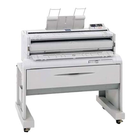
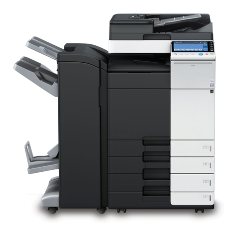
Ricoh B286 User manual

B286/B289
SERVICE MANUAL
003165MIU


B286/B289
SERVICE MANUAL


B286/B289
SERVICE MANUAL
003165MIU


It is the reader's responsibility when discussing the information contained
within this document to maintain a level of confidentiality that is in the best
interest of Ricoh Americas Corporation and its member companies.
NO PART OF THIS DOCUMENT MAY BE REPRODUCED IN ANY
FASHION AND DISTRIBUTED WITHOUT THE PRIOR
PERMISSION OF RICOH AMERICAS CORPORATION.
All product names, domain names or product illustrations, including
desktop images, used in this document are trademarks, registered
trademarks or the property of their respective companies.
They are used throughout this book in an informational or editorial fashion
only and for the benefit of such companies. No such use, or the use of
any trade name, or web site is intended to convey endorsement or other
affiliation with Ricoh products.
©2007 RICOH Americas Corporation. All rights reserved.


The Service Manual contains information
regarding service techniques, procedures,
processes and spare parts of office equipment
distributed by Ricoh Americas Corporation.
Users of this manual should be either service
trained or certified by successfully completing a
Ricoh Technical Training Program.
Untrained and uncertified users utilizing
information contained in this service manual to
repair or modify Ricoh equipment risk personal
injury, damage to property or loss of warranty
protection.
Ricoh Americas Corporation
WARNING


LEGEND
PRODUCT CODE COMPANY
Gestetner LANIER RICOH SAVIN
B286 GWD2004 LW324 MPW2400 2404WD
B289 GWD2006 LW336 MPW3600 2406WD
DOCUMENTATION HISTORY
REV. NO. DATE COMMENTS
* 07/2007 Original Printing


SM i B286/B289
B286/B289
TABLE OF CONTENTS
INSTALLATION
1. INSTALLATION ........................................................................... 1-1
1.1 PREPARATION ......................................................................................... 1-1
1.1.1 ENVIRONMENT ............................................................................... 1-1
1.1.2 MINIMUM SPACE REQUIREMENTS............................................... 1-2
1.1.3 MACHINE LEVEL ............................................................................. 1-2
1.1.4 POWER SOURCE ............................................................................ 1-2
1.1.5 INSTALLATION OVERVIEW ............................................................ 1-3
Installation Flow.................................................................................... 1-3
SP and User Tool Settings Required for Installation ............................ 1-4
1.2 MAIN MACHINE INSTALLATION (B286) .................................................. 1-7
1.2.1 ACCESSORY CHECK...................................................................... 1-7
1.2.2 MACHINE INSTALLATION PROCEDURE ....................................... 1-8
Removing the Shipping Material........................................................... 1-8
Set the Operation Panel Position ......................................................... 1-9
Setting the Main Machine on the Roll Feeder (B851/B852) or Table (B854)
............................................................................................................. 1-9
Leveling the Main Machine and Attaching Leg Covers....................... 1-14
Developer ........................................................................................... 1-16
Toner Cartridge Installation ................................................................ 1-17
Enter Developer Lot Numbers ............................................................ 1-19
Mix Developer and Initialize ID Sensor............................................... 1-19
1.2.3 MAIN MACHINE FINAL INSTALLATION........................................ 1-21
Select the Tray Paper Size and Type................................................. 1-21
Testing the Main Machine Circuit Breaker.......................................... 1-21
Main Machine Accessories................................................................. 1-22
Roll Feeder, Table Accessories.......................................................... 1-23
Copy Check........................................................................................ 1-25
Enable Onboard NIB, USB Functions ................................................ 1-25
1.2.4 MOVING THE MACHINE................................................................ 1-25

B286/B289 ii SM
1.3 ORIGINAL HANGER (D311).................................................................... 1-27
1.3.1 ACCESSORY CHECK.................................................................... 1-27
1.3.2 INSTALLATION .............................................................................. 1-27
1.4 ROLL FEEDER (B851/B852) ................................................................... 1-28
1.4.1 ACCESSORY CHECK.................................................................... 1-28
1.4.2 ROLL FEEDER INSTALLATION PROCEDURE............................. 1-29
Setting the Main Machine on the Roll Feeder .................................... 1-29
Opening the Roll Feeder and Removing Shipping Material................ 1-30
Leveling the Main Machine and Attaching Leg Covers....................... 1-35
Connecting the Main Machine and Roll Feeder.................................. 1-37
Attaching the Narrow Mylars to the Main Machine ............................. 1-40
Attaching the Wide Mylars to the Back of the Roll Feeder ................. 1-41
Securing the Power Cord ................................................................... 1-42
Installing the Paper Rolls.................................................................... 1-42
Attaching the Lower Output Tray, Exit Guide Plates .......................... 1-43
Entering the Cut Length Adjustment................................................... 1-44
Setting Paper Sizes/Types for the Tray 1 (1st Roll), Tray 2 (2nd Roll) . 1-44
1.5 PAPER CASSETTE (B853) ..................................................................... 1-45
1.5.1 ACCESSORY CHECK.................................................................... 1-45
1.5.2 PAPER CASSETTE INSTALLATION PROCEDURE...................... 1-45
1.6 TABLE (B854).......................................................................................... 1-48
1.6.1 ACCESSORY CHECK.................................................................... 1-48
1.6.2 INSTALLATION PROCEDURE....................................................... 1-49
Setting the Main Machine on the Table .............................................. 1-49
Leveling the Main Machine and Attaching Leg Covers....................... 1-50
Attaching the Guide Plate................................................................... 1-50
Connecting the Main Machine and Table ........................................... 1-50
Attach the Narrow Mylars to the Main Machine .................................. 1-52
Attach the Wide Mylars to the Back of the Table................................ 1-53
Attaching the Stopper Brackets .......................................................... 1-54
Table Accessories .............................................................................. 1-54
1.7 INSTALLATION OF MFP OPTIONS ........................................................ 1-56
1.7.1 OVERVIEW..................................................................................... 1-56
1.7.2 ENABLING THE ONBOARD FEATURES....................................... 1-57
1.7.3 USING SD CARDS ......................................................................... 1-58
Removing the SD Card Slot Cover..................................................... 1-58

SM iii B286/B289
SD Card Slot Assignments................................................................. 1-58
Restrictions and Precautions on the Use of SD Cards ....................... 1-59
Application Move ................................................................................ 1-60
Undo Exec.......................................................................................... 1-60
1.7.4 PRINTER OPTION TYPE W3600 (D320) ....................................... 1-61
Accessories ........................................................................................ 1-61
Installation .......................................................................................... 1-62
1.7.5 SCANNER OPTION TYPE W3600 (D321) ..................................... 1-63
Accessories ........................................................................................ 1-63
Installation .......................................................................................... 1-63
1.7.6 FILE FORMAT CONVERTER TYPE C (B609-04) .......................... 1-64
Accessories ........................................................................................ 1-64
Installation .......................................................................................... 1-64
1.7.7 INTERFACE PCB (D329) ............................................................... 1-67
Accessories ........................................................................................ 1-67
Installation .......................................................................................... 1-67
1.7.8 IEEE802.11B INTERFACE UNIT TYPE H (G813-45)/TYPE I (G874-39)
1-69
Accessories ........................................................................................ 1-69
Installation .......................................................................................... 1-69
1.7.9 GIGABIT ETHERNET BOARD TYPE A (G874-01) ........................ 1-70
Accessories ........................................................................................ 1-70
Installation .......................................................................................... 1-70
1.7.10 DATA OVERWRITE SECURITY UNIT TYPE D (B735-18) ... 1-72
Accessories ........................................................................................ 1-72
Before You Begin…............................................................................ 1-72
Seal Check and Removal................................................................... 1-72
Installation .......................................................................................... 1-72
Check Operation of the DOS Application ........................................... 1-74
1.7.11 USB HOST INTERFACE UNIT TYPE 7300 (G819-01) ......... 1-75
Accessories ........................................................................................ 1-75
Installation .......................................................................................... 1-75

B286/B289 iv SM
1.7.12 BROWSER UNIT TYPE C (B828-03) .................................... 1-76
Accessories ........................................................................................ 1-76
Installation .......................................................................................... 1-76
1.7.13 VM CARD TYPE E (D338-01, -02, -03) ................................. 1-77
Accessories ........................................................................................ 1-77
Installation .......................................................................................... 1-77
1.8 REAR STACKER (D312) ......................................................................... 1-79
1.8.1 ACCESSORIES .............................................................................. 1-79
1.8.2 INSTALLATION .............................................................................. 1-80
PREVENTIVE MAINTENANCE
2. PREVENTIVE MAINTENANCE ................................................... 2-1
2.1 PM TABLE ................................................................................................. 2-1
2.1.1 MAIN MACHINE (B286).................................................................... 2-1
2.1.2 ROLL FEEDER (B851/B852) ............................................................ 2-4
2.1.3 PAPER CASSETTE (B853) .............................................................. 2-5
2.1.4 FOLDER FD/MANUAL FEEDER (D889) .......................................... 2-5
2.1.5 MANUAL FEEDER (D333)................................................................ 2-6
2.2 CLEANING THE ENTRANCE SPURS....................................................... 2-6
2.3 LUBRICATION POINTS............................................................................. 2-7
2.3.1 DEVELOPMENT SECTION .............................................................. 2-7
2.3.2 FUSING GEARS............................................................................... 2-7

SM v B286/B289
REPLACEMENT AND ADJUSTMENT
3. REPLACEMENT AND ADJUSTMENT ........................................ 3-1
3.1 COMMON PROCEDURES ........................................................................ 3-1
3.1.1 BEFORE WORKING ON THE MAIN MACHINE............................... 3-1
3.1.2 SIDE COVERS ................................................................................. 3-2
3.1.3 REAR COVER .................................................................................. 3-3
3.1.4 PAPER EXIT UNIT ........................................................................... 3-3
3.1.5 UNLOCKING, OPENING THE ORIGINAL UNIT............................... 3-4
3.1.6 REMOVING THE ORIGINAL FEED UNIT ........................................ 3-5
3.1.7 RAISING AND LOCKING THE SCANNER UNIT.............................. 3-6
3.1.8 TONER HOPPER COVER................................................................ 3-7
3.1.9 IDLE REGISTRATION ROLLER PANEL .......................................... 3-7
3.1.10 MANUAL FEED TABLE, ORIGINAL FEED SENSOR COVER ... 3-8
3.1.11 DRAWER FRONT COVER ......................................................... 3-9
3.2 SCANNER ............................................................................................... 3-10
3.2.1 ORIGINAL WIDTH SENSORS, ORIGINAL SET SENSOR, SCANNER
SWITCH................................................................................................... 3-10
3.2.2 ORIGINAL FEED UNIT ROLLERS ................................................. 3-11
3.2.3 EXPOSURE GLASS ....................................................................... 3-12
3.2.4 CIS.................................................................................................. 3-13
3.2.5 SMDB, VDB .................................................................................... 3-14
3.2.6 SIB, CGB POWER PACK ............................................................... 3-15
3.3 AROUND THE DRUM.............................................................................. 3-16
3.3.1 CHARGE CORONA WIRE, GRID WIRE, WIRE CLEANER ........... 3-16
3.3.2 QUENCHING LAMPS..................................................................... 3-17
3.3.3 LPH (LED PRINT HEAD) ................................................................ 3-18
3.3.4 TRANSFER CORONA, SEPARATION CORONA WIRES.............. 3-19
3.4 DEVELOPMENT...................................................................................... 3-21
3.4.1 DEVELOPMENT UNIT ................................................................... 3-21
3.4.2 DEVELOPER .................................................................................. 3-22
3.4.3 PAPER SET SENSOR, REGISTRATION SENSOR....................... 3-24
3.4.4 TONER SUPPLY CLUTCH............................................................. 3-25
3.4.5 DEVELOPMENT FILTER................................................................ 3-25

B286/B289 vi SM
3.4.6 USED TONER COLLECTION BOTTLE, TONER OVERFLOW SENSOR
3-26
3.5 DRUM ...................................................................................................... 3-27
3.5.1 DRUM UNIT.................................................................................... 3-27
3.5.2 CLEANING BLADE......................................................................... 3-29
3.5.3 ID SENSOR, PICK-OFF PAWLS, PICK-OFF PAWL SOLENOID... 3-30
3.6 PAPER FEED .......................................................................................... 3-31
3.6.1 REGISTRATION CLUTCH, REGISTRATION ROLLER.................. 3-31
3.6.2 ROLL 1 PAPER FEED CLUTCH, FEED ROLLER.......................... 3-33
3.6.3 ROLL 2 PAPER CLUTCH, FEED ROLLER .................................... 3-34
3.6.4 RF EXIT SENSOR .......................................................................... 3-35
3.6.5 ROLL FEED MOTOR...................................................................... 3-35
3.6.6 CUTTER MOTOR, HP SENSORS.................................................. 3-36
3.6.7 ROLL PAPER END SENSORS ...................................................... 3-37
3.6.8 CASSETTE FEED ROLLER ........................................................... 3-38
3.6.9 CASSETTE RELAY SENSOR, CASSETTE END SENSOR........... 3-38
3.6.10 CASSETTE FEED MOTOR, CASSETTE OPEN SENSOR....... 3-39
3.6.11 CASSETTE FEED CLUTCH ..................................................... 3-40
3.7 FUSING ................................................................................................... 3-41
3.7.1 PRESSURE SPRING ADJUSTMENT ............................................ 3-41
3.7.2 HOT ROLLER STRIPPERS............................................................ 3-42
3.7.3 FUSING EXIT SENSOR ................................................................. 3-42
3.7.4 PRESSURE ROLLER THERMISTORS.......................................... 3-43
3.7.5 PRESSURE ROLLER STRIPPERS................................................ 3-44
3.7.6 EXIT UNIT SWITCH ....................................................................... 3-44
3.7.7 FUSING UNIT ................................................................................. 3-45
3.7.8 FUSING CLEANING ROLLER........................................................ 3-46
3.7.9 FUSING LAMP................................................................................ 3-47
3.7.10 HOT ROLLER ........................................................................... 3-48
3.7.11 PRESSURE ROLLER ............................................................... 3-48
3.7.12 HOT ROLLER THERMISTOR, THERMOSTATS...................... 3-49
3.8 MOTORS ................................................................................................. 3-50
3.8.1 SCANNER MOTOR ........................................................................ 3-50
3.8.2 DRUM MOTOR............................................................................... 3-51
3.8.3 FUSING MOTOR, MAIN MOTOR................................................... 3-51
3.8.4 USED TONER BOTTLE MOTOR ................................................... 3-53

SM vii B286/B289
3.9 BOARDS.................................................................................................. 3-54
3.9.1 MCU/IPU/MB .................................................................................. 3-54
3.9.2 PSU/CIRCUIT BREAKER ............................................................... 3-58
3.9.3 CONTROLLER BOARD.................................................................. 3-60
3.9.4 NVRAM........................................................................................... 3-63
NVRAM Upload .................................................................................. 3-63
NVRAM Download ............................................................................. 3-63
3.9.5 T&S POWER PACK........................................................................ 3-64
3.9.6 RFDB (ROLL FEEDER DRIVE BOARD) ........................................ 3-65
3.9.7 SFDB (SHEET FEED DRIVE BOARD)........................................... 3-65
3.10 OTHERS ............................................................................................ 3-67
3.10.1 HDD .......................................................................................... 3-67
3.10.2 COOLING FAN, OZONE FILTER.............................................. 3-68
3.11 SP ADJUSTMENTS ........................................................................... 3-70
3.11.1 IMAGE ADJUSTMENT WITH SP CODES ................................ 3-70
Step 1: Magnification for Paper Type: Plain ....................................... 3-70
Step 2: Scanning Magnification .......................................................... 3-71
Step 3: Magnification for Paper Type: Translucent............................. 3-71
Step 4: Magnification for Paper Type: Film ........................................ 3-72
Step 5: Scanner Mask Setting ............................................................ 3-72
Step 6: Erase Margins........................................................................ 3-72
Step 7: Printer: Leading Edge, Side-to-Side Registration................... 3-73
Step 8: Scanner Mask Setting ............................................................ 3-74
Step 9: Erase Margins........................................................................ 3-74
Step 10: Scanner Registration............................................................ 3-75
Step 11: Printer: Cut Length............................................................... 3-75
Step 12: Synchro Cut (Trailing Edge Registration)............................. 3-76
3.11.2 CIS ADJUSTMENT WITH SP CODES...................................... 3-77
To Print the CIS Adjustment Pattern .................................................. 3-77
To Adjust the Image at the CIS Joints ................................................ 3-78
3.11.3 LPH ADJUSTMENT WITH SP CODES..................................... 3-80
Doing SP Adjustment Settings for a Replacement LPH ..................... 3-80
To Print Pattern IPU Test Pattern 10.................................................. 3-81
Main Scan Adjustment: White, Black Vertical Lines ........................... 3-82
Main Scan Adjustment: LED Light Level at LPH Joints ...................... 3-83
Adjusting LPH Alignment.................................................................... 3-83

B286/B289 viii SM
3.11.4 LPH DENSITY ADJUSTMENT WITH SP CODES .................... 3-85
To Print the IPU Test Pattern 2 .......................................................... 3-85
To Correct Pattern Density................................................................. 3-86
TROUBLESHOOTING
4. TROUBLESHOOTING ................................................................. 4-1
4.1 SERVICE CALL CONDITIONS.................................................................. 4-1
4.2 SC CODE DESCRIPTIONS....................................................................... 4-3
4.2.1 SC1XXX............................................................................................ 4-3
4.2.2 SC2XXX............................................................................................ 4-3
4.2.3 SC3XXX............................................................................................ 4-4
4.2.4 SC4XXX............................................................................................ 4-5
4.2.5 SC5XXX............................................................................................ 4-6
4.2.6 SC6XXX.......................................................................................... 4-11
4.2.7 SC7XXX.......................................................................................... 4-14
4.2.8 SC8XXX.......................................................................................... 4-16
4.2.9 SC9XXX.......................................................................................... 4-23
4.3 JAM CODE TABLES................................................................................ 4-28
4.3.1 OVERVIEW..................................................................................... 4-28
4.3.2 SCANNER JAMS............................................................................ 4-29
Scanner Standby Jams ...................................................................... 4-29
Scanner Late Jams ............................................................................ 4-31
Scanner Lag Jams ............................................................................. 4-31
4.3.3 PLOTTER (PRINTER) JAMS.......................................................... 4-31
Plotter Standby Jams ......................................................................... 4-31
Plotter Late Jams ............................................................................... 4-32
Plotter Lag Jams ................................................................................ 4-32
4.3.4 FOLDER UNIT JAMS ..................................................................... 4-33
Folder Unit Standby Jams .................................................................. 4-33
Folder Unit Late Jams ........................................................................ 4-34
Folder Unit Lag Jams ......................................................................... 4-35
4.4 COVER OPEN ......................................................................................... 4-36
4.5 FUSES ..................................................................................................... 4-37
4.6 IMAGE PROBLEM TROUBLESHOOTING .............................................. 4-38
This manual suits for next models
1
Table of contents
Other Ricoh Copier manuals

Ricoh
Ricoh MP 401 spf User manual

Ricoh
Ricoh Pro 8100S User manual

Ricoh
Ricoh FT3813, FT4615, FT4618 User manual

Ricoh
Ricoh A250 User manual

Ricoh
Ricoh MP 2000LE User manual

Ricoh
Ricoh A163 User manual

Ricoh
Ricoh MPC 1500sp User manual

Ricoh
Ricoh FW770 User manual

Ricoh
Ricoh Aficio MP C3002 User manual

Ricoh
Ricoh Aficio MP 1600L User manual

Ricoh
Ricoh A-C4 User manual

Ricoh
Ricoh Aficio FT4027 User manual

Ricoh
Ricoh A069 User manual

Ricoh
Ricoh FT6645 User manual
Ricoh
Ricoh Aficio 2045e User instructions

Ricoh
Ricoh Aficio SP 5200S User manual

Ricoh
Ricoh A229 User manual

Ricoh
Ricoh FT7770 User manual

Ricoh
Ricoh aficio 1013 User manual

Ricoh
Ricoh FT 4015 User manual