Ricoh FT8880 User manual

RICOH FT8880
SERVICE MANUAL
This manual is an insert upgrade which covers only the
points where the FT8880 (A083) differs from the FT8780
(A084). Refer to the FT8780 service manual for any items
not covered here.

IMPORTANT SAFETY NOTICES
PREVENTION OF PHYSICAL INJURY
1. While the machine warms up, it will suddenly start turning to perform the
process control data initialization. Keep hands away from any mechanical
and electrical components during this period.
2. Before disassembling or assembling parts of the copier and peripherals,
make sure that the copier and the second sorter power cord is unplugged.
3. The wall outlet should be near the copier and easily accessible.
4. Note that some components of the copier, the paper tray unit, and the
peripherals are supplied with electrical voltage even if the main switch is
turned off.
5. If any adjustment or operation check has to be made with exterior covers
off or open while the main switch is turned on, keep hands away from
electrified or mechanically driven components.
6. The inside and the metal parts of the fusing unit become extremely hot
while the copier is operating. Be careful to avoid touching those
components with your bare hands.
HEALTH SAFETY CONDITIONS
1. Never operate the copier without the ozone filters installed.
2. Always replace the ozone filters with the specified ones at the specified
intervals.
3. Toner and developer are non-toxic, but if you get either of them in your
eyes by accident, it may cause temporary eye discomfort. Try to remove
with eye drops or flush with water as first aid. If unsuccessful, get medical
attention.

OBSERVANCE OF ELECTRICAL SAFETY STANDARDS
1. The copier and its peripherals must be installed and maintained by a
customer service representative who has completed the training course
on those models.
2. The RAM board on the main control boards on the copier and the RDH
has a lithium battery which can explode if replaced incorrectly. Replace
the battery only with an identical one. The manufacturer recommends
replacing the entire RAM board. Do not recharge or burn this battery.
Used batteries must be handled in accordance with local regulations.
SAFETY AND ECOLOGICAL NOTES FOR DISPOSAL
1. Do not incinerate the toner cartridge or the used toner. Toner dust may
ignite suddenly when exposed to open flame.
2. Dispose of used toner, developer, and photoconductors according to
local regulations.
3. Dispose of replaced parts in accordance with local regulations.
4. When keeping used lithium batteries in order to dispose of them later, do
not put more than 100 batteries per sealed box. Storing larger numbers or
not sealing them apart may lead to chemical reactions and heat build-up.

SECTION 1
OVERALL MACHINE
INFORMATION

1. SPECIFICATIONS
Main Copier
Copier
Configuration: Console
Copy Process: Dry Electrostatic Transfer System
Originals: Sheet/Book
Original Size: Maximum: 11" x 17", A3
Copy Paper Size: Maximum: 1st and 2nd tray 81/2" x 14", A4
3rd tray 11" x 17", A3
Minimum: 1st and 3rd tray 51/2" x 81/2", A5
2nd tray 81/2" x 11", A4
Copy Paper Weight: Standard Copying: 14 ~ 42 lb, 52 ~ 157 g/m2
Duplex Copying: 17 ~ 28 lb, 64 ~ 105 g/m2
Warm Up Time: Within 8.0 minutes (room temp. 68°F, 20°C)
First Copy Time: 4.8 seconds (81/2" x 11", A4, feed from 2nd tray)
Copying Speed: 80 copies/minute (81/2" x 11", A4)
60 copies/minute (11" x 17", A3)
Optional Equipment: Menu Reader
Key Counter
Guidance ROM Kit
Reproduction Ratios: See the following table:
LT/DLT version A4/A3 version
Enlargement 200% 200%
155% 141%
129% 122%
121% 115%
Full Size 100% 100%
Reduction
93% 93%
77% 82%
74% 71%
65% 65%
50% 50%
Overall
Information
5 June 1992 SPECIFICATIONS
1-1

Zoom: 50 ~ 200%
Toner Replenishment: Cartridge exchange (1,500 g)
Paper Feed: 1st tray (550 sheets)
2nd tray (3,000 sheets)
3rd tray (1,500 Sheets)
Power Source: 120 V, more than 20 A (LT/DLT version)
220, 230, 240 V, more than 10 A (A4/A3 version)
Power Consumption:
Maximum during LT/DLT version A4/A3 version
Stand-by 2.01 kw 2.00 kw
Copying Cycle 1.85 kw 1.89 kw
Dimensions: Copier Only: 65.4" x 30.0" x 56.9"
(1660 x 760 x 1444.5 mm)
With Finisher: 83.1" x 30.0" x 56.9"
(2110 x 760 x 1444.5 mm)
Weight: Copier Only: 917 lb/422 kg
With Finisher: 1027 lb/472 kg
Noise Emission: With Finisher/RDH:
Maximum: less than 70 db
Copy-cycle: less than 69 db (average)
Warm-up: less than 42 db
SPECIFICATIONS 5 June 1992
1-2

Recycling Document Handler
Original Size:
Stack feed mode Single feed mode CFF mode
Maximum 11" x 17", A3 11" x 17", A3 11" x 91/2"
81/2" x 12"
11" x 147/8"
Minimum 8" x 101/2", A4 51/2" x 81/2", A5
Original Weight:
Stack feed mode Single feed mode CFF mode
Maximum 28 lb, 105 g/m243 lb, 165 g/m220 lb, 80 g/m2
Minimum 17 lb, 64 g/m214 lb, 52 g/m217 lb, 64 g/m2
Number of originals to be set:
Weight
Size 64~81 g/m2
17~21 lb 82~105 g/m2
22~28 lb
A3/11" x 17" 30 sheets 20 sheets
Others 50 sheets 30 sheets
Number of Recycles: Maximum: 60 times
CFF Original Stack Height:Maximum: 50 mm
Original Set: First sheet on top, stack face down
Overall
Information
5 June 1992 SPECIFICATIONS
1-3

3. MECHANICAL COMPONENT LAYOUT
3.2 RDH
1234567
15 8
14 13 12 10 9
11
1. Inverter Roller
2. Inverter Exit Roller
3. Air Knife Nozzle
4. Exit Roller
5. Original Guide
6. Feed-in Belt
7. Original Stopper
8. Right Turn Roller
9. Belt Drive Roller
10. Transport Belt
11. Transport Rollers
12. Original Feed Roller
13. Inverter Entrance Roller
14. Single Feed Exit Gate
15. Inverter Middle Roller
MECHANICAL COMPONENT LAYOUT 5 June 1992
1-4

4. ELECTRICAL COMPONENT DESCRIPTIONS
Refer to the electrical component layout on the reverse side of the Point to
Point (Water proof paper) index numbers.
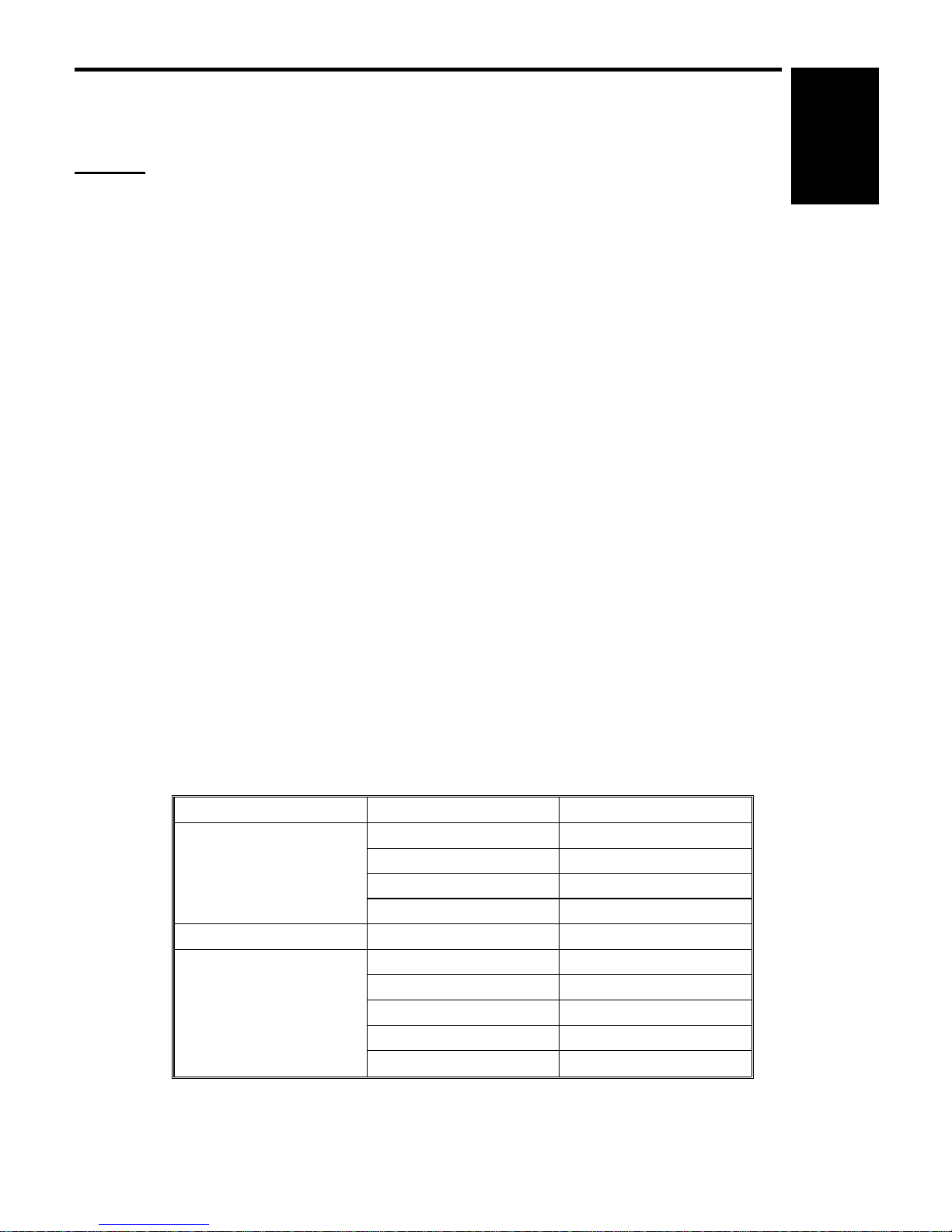
4.2 RDH
Name Function Index No.
Motors
Feed Drives the feed and transport rollers. 3
Belt Drive Drives the transport belt. 7
Inverter Drives the inverter and exit rollers. 34
Blower Supplies air to the air knife and draws air from the
vacuum section. 5
Separator Drives the original separator. 21
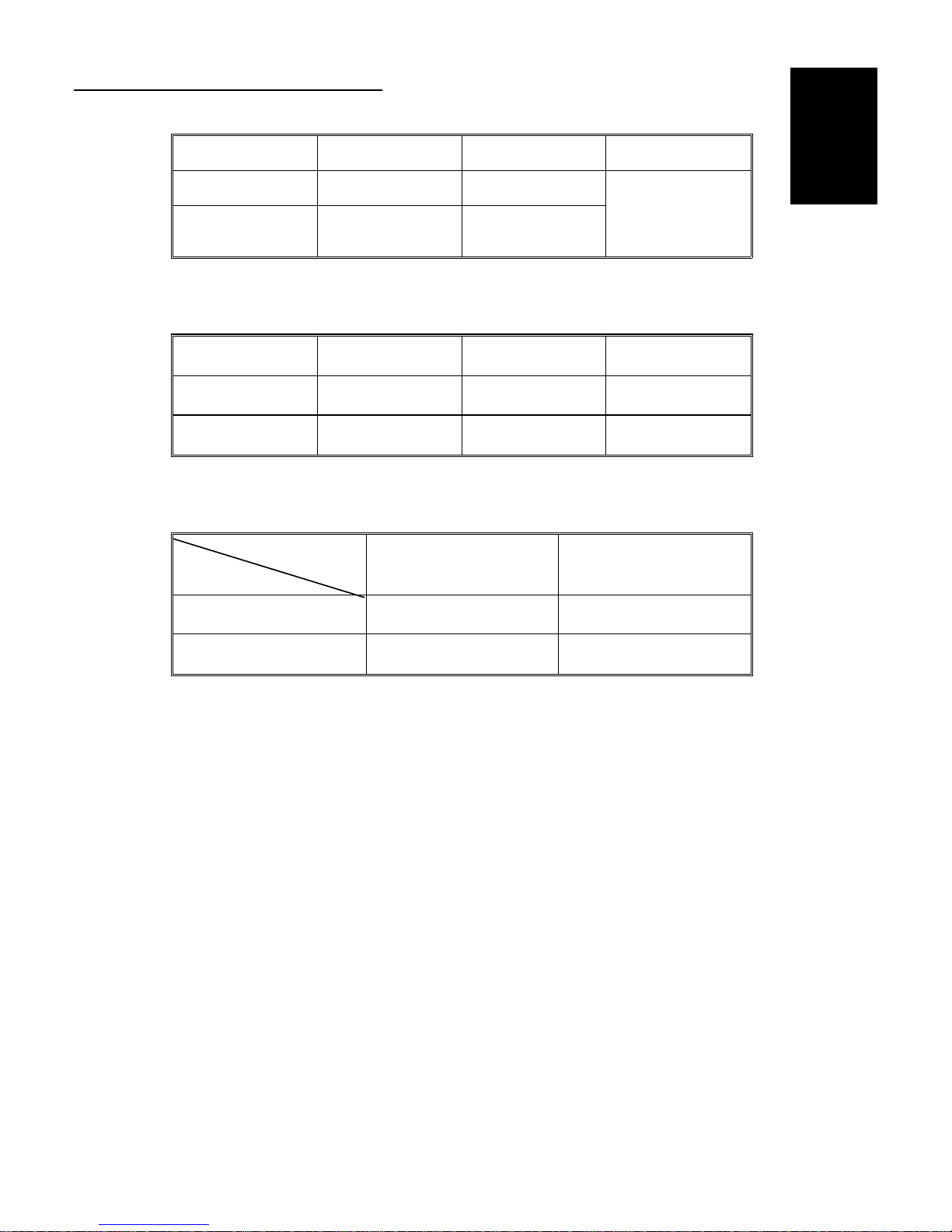
Sensors
Original Set Detects if the original is set on the document handler. 31
Entrance Detects the original leading edge and de-energizes
the feed belt drive clutch. 33
1st Transport Detects jams in the transport section. 16
2nd Transport Detects the original leading edge and lowers the
original feed motor speed. 15
Registration Detects the original trailing edge for the original stop
position calculation. 12
Inverter Entrance Detects jams in the transport belt section. 24
1st Inverter Detects the original trailing edge and reverses the
inverter drive motor rotation. 29
2nd Inverter Detects the original leading edge and energizes exit
roller release solenoid. 30
Exit Detects the original leading edge and lowers the
inverter drive motor speed. 32
Single Feed Set Detects the leading edge of the original in the single
feed table and turns the original feed motor. 13
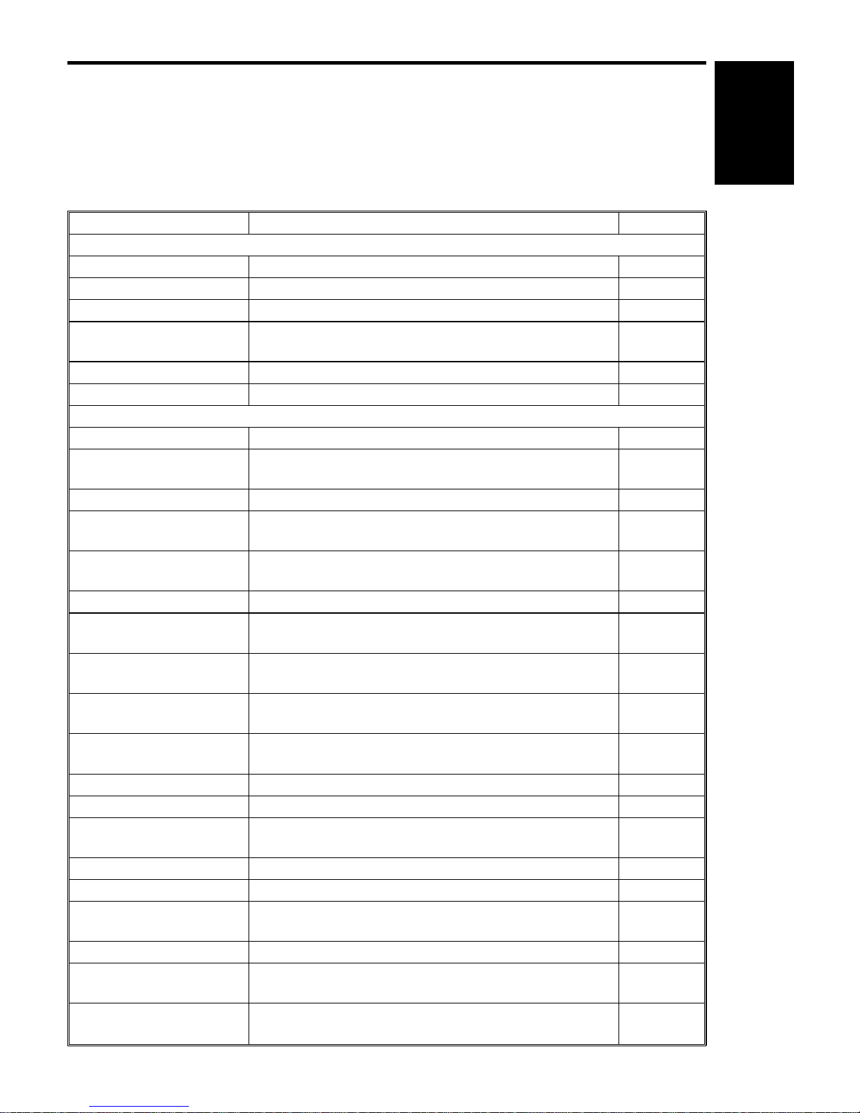
Single Feed Exit Detects jams in single feed mode. 25
Lift Detects if the RDH is open. 2
CFF Detects if the computer form is set in the CFF guide.
Counts the holes lined up to the computer form. 9
Original Length Detects if the original stopper is set for 81/2" position. 19
Original Height Detects the original height on the RDH. 20
Separator H.P. Detects if the original separator is in the home
position. 22
Separator Detects if the last original of the original stack is fed. 23
Inverter Unit Cover
(Switch) Detect if the inverter unit cover is opened. 27
Original Width
(Potentiometer) Detects the original width in the stack feed mode. 17
Overall
Information
5 June 1992 ELECTRICAL COMPONENT DESCRIPTIONS
1-5

Name Function Index No.
Single Feed Original
Width (Potentiometer) Detects the original width in the single feed mode. 14
Solenoids
Vacuum Shutter Closes the vacuum shutter. 4
Single Feed Gate Lowers the single feed gate. 8
Single Feed Exit Lifts the single feed exit gate. 26
Exit Roller Releases the exit driven rollers from the exit drive
rollers. 28
Clutches
Feed Belt Drive Transmits the original feed motor drive to the feed
belt rollers. 10
Feed Belt Brake Stops the feed belt rotation. 11
PCBs
Main Control Controls overall RDH operation. 6
Blower Motor Control Controls the vacuum motor operation. 1
Indicator Indicates the single feed mode indicators. 18
ELECTRICAL COMPONENT DESCRIPTIONS 5 June 1992
1-6

SECTION 2
DETAILED SECTION
DESCRIPTIONS

6. DEVELOPMENT
6.4.3 Bias for the ID Sensor Pattern
The ID sensor pattern cannot always be used for the image density detection
due to the position of the ID sensor and both the positioning and size of the
ID sensor pattern on the drum.
The outside of the exposure glass (no light) is exposed on the drum and used
as the ID sensor pattern in reduction mode.
The potential of the drum in these cases, the no light and the ID sensor
pattern exposure, is not the same. So the ID sensor bias (VBP) is determined
using two base voltages, V0for the no-light condition and Vd for the pattern.
VBP (no light) = --360 + V0(Reproduction ratio <77%)
VBP (ID Pattern) = --360 + Vd (Reproduction ratio ≥77%)
The Vd value which is determined during the process control data
initialization will be used.
V01 and V02, which are explained in the process control section, are used for
the VBP calculation as the V0(drum potential after the charge corona) value.
The VBP can be changed by the SP mode (Toner Density Correction).
The following compensation will be applied to the above VBP.
Setting LN H VH
(V) --60 0+60 +120 Default: H (+60 V)
VLPattern
ID Sensor Pattern
Outside
ID Sensor
Exposure Glass
Enlargement
Reduction
Full Size
Detailed
Descriptions
5 June 1992 DEVELOPMENT
2-1

16. RDH
16.1 OVERVIEW
16.1.1 No Inversion Original Cycle
When the start key is pressed, the blower motor start to rotate. It supplies air
to the air knife and draws air from the vacuum section. Sheets are separated
at the leading edge [A] of the paper stack. The air comes from the nozzle [B]
and the bottom sheet of the stack paper is held against the feed-in belts [C]
by air suction [D]. The feed motor drives the feed drive [E], transport [F], and
right turn [G] rollers. The bottom sheet of the paper is delivered through the
feed drive, transport, right turn rollers to the registration section [H] and is
stopped. To stop the original sheet at the proper position in the registration
section, the feed motor rotation speed is reduced by half when the 2nd
transport sensor [I] detects the leading edge of the original. The belt drive
motor then starts to rotate the transport belt [J] to direct the sheet of paper
onto exposure glass. At the same time, the next original is fed.
[D]
[F]
[E] [B] [A] [C] [J] [I]
[H] [G]
RDH 5 June 1992
2-2

At the appropriate time, the transport belt delivers the original on the
exposure glass to the inverter section [A], and the following original is moved
onto the exposure glass, and the 3rd sheet of original is fed. The 1st original
is passed into the inverter section through the inverter entrance [B], inverter
middle [C], and inverter [D] rollers until the trailing edge of the original is
detected by the 1st inverter sensor [E]. The inverter middle [C] and inverter
[D] rollers then rotate in the opposite direction. The inverter exit rollers [F]
rotates only in the paper exit direction. However, the contact between the
inverter exit roller [F] and inverter exit driven roller [G] is released when the
2nd inverter sensor [H] is activated by the original. This way, the inverter exit
roller does not interfere with the original switch back cycle while the inverter
middle and inverter rollers begin reverse rotation. The original is delivered
through the inverter entrance [B] and inverter exit [F] rollers to the original
table. This continues until all originals have been returned to the original
table. The originals are stacked on the original table where they wait for the
next copy cycle.
[B]
[G] [F]
[E]
[C]
[D]
[H]
[A]
Detailed
Descriptions
5 June 1992 RDH
2-3

16.1.2 Inversion Original Cycle
Until the original reaches to the inverter section [A], the sequence is the same
as for no inversion original cycle. The inverter rollers [B] rotate in the original
exit direction. The original is now inverted and exited to the original table [C].
This continues until all originals have been inverted. The inverted originals
are then fed from the original table for copying of the reverse side. The
sequence is the same as for the front side copying. The originals return and
are stacked on the original table where they wait for the next copy cycle.
[B]
[B] [C]
[A]
RDH 5 June 1992
2-4

16.1.3 1 Sided Original 2 Sided Copy Mode
No inversion original cycle is used for this mode.
All the originals [A] are fed starting from the bottom original sheet. First, odd
numbered originals (in case of the illustration: 1st and 3rd originals) are
copied and even numbered originals copy is skipped. The copied paper [B] is
stacked in the duplex tray. The originals are return to the original table, and
the original feed is then repeated. This time the odd numbered originals copy
is skipped and even numbered originals are copied on the reverse side of the
copy paper [C], which is fed from the duplex tray.
[A]
[B] [C]
Detailed
Descriptions
5 June 1992 RDH
2-5

16.1.4 2 Sided Original 2 Sided Copy Mode
Inversion original cycle is used for this mode. All the originals [A] are fed
starting from the bottom original sheet. First, the front side of the originals are
copied. The copied paper [B] is stacked in the duplex tray. The originals [C]
are inverted and return to the original table. The original feed is then
repeated. This time the reverse side of the originals are copied on the
reverse side of the copy paper [D], which is fed from the duplex tray.
[A]
[B] [D]
[C]
RDH 5 June 1992
2-6

16.1.5 2 Sided Original 1 Sided Copy Mode
Inversion original cycle is used for this mode. All the originals [A] are fed
starting rom the bottom original sheet. Firstly, the front side of all the originals
are copied and the copied paper [B] is stacked in the duplex tray. The
originals [C] are inverted and return to the original table. The original feed is
then repeated. This time, the bottom copy sheet is fed from the duplex tray
and exited from the copier without copying [C]. The reverse side of the
bottom original sheet [D] is then copied to paper [E], which is fed from the
paper tray, and the copy is exited from the copier [E]. This copy sequence
exiting from the duplex tray followed by the paper tray is alternately repeated.
[A]
[B] [D]
[C][E]
Detailed
Descriptions
5 June 1992 RDH
2-7

16.2 ORIGINAL SET
16.2.1 Stack Feed Mode
1. Original set detection
The originals are detected by the original set sensor [A] when they are
stacked on the original table.
2. Size detection
The original width is detected by the original width sensor [B] under the front
original guide [C]. Moving the guide changes the value of the sensor. (The
sensor is a potentiometer.) The front original guide and rear original guide [D]
are moved by the racks [E] and pinion [F] at the same time. The actuator [G]
of the original stopper activates the original length sensor [H]
(photo-interrupter) to detect if the original stopper is set for the 81/2 inch
position. LG (81/2" x 14" = 216 x 356 mm) or B4 (257 x 364 mm) size is
distinguished by the combination of the original length sensor (activated or
not) and the value of the original width sensor. This is because the LG and
B4 widths are very close.
[E]
[A]
[D]
[C]
[F]
[G]
[H]
[B]
RDH 5 June 1992
2-8

3. Original separator
The original stack which has been fed and returned to the original table, and
the original stack which has not been fed yet, are separated by the original
separator [A] mechanism.
When the start key is pressed, the separator motor [B] rotates until the
original separator actuator [C] activates the separator home position sensor
[D]. The original separator is set on the original top sheet. The originals which
are fed and returned to the original table are stacked on the original
separator. When the last original (top sheet under the original separator) is
fed from the original table, the original separator drops and activates the
separator sensor [E].
If the next copy cycle continues, the separator motor rotates and the original
separator is set on the original top sheet again after the trailing edge of the
last original sheet passes through the exit sensor [F].
[E]
[B]
[E]
[A]
[D]
[C] [E]
[F]
Detailed
Descriptions
5 June 1992 RDH
2-9
Table of contents
Other Ricoh Copier manuals

Ricoh
Ricoh FW770 User manual

Ricoh
Ricoh DSc332 User manual

Ricoh
Ricoh FT8680 User manual

Ricoh
Ricoh Pro C720s User manual

Ricoh
Ricoh M022 Installation instructions

Ricoh
Ricoh A229 User manual

Ricoh
Ricoh Aficio MP 171 Quick start guide

Ricoh
Ricoh RN-MF2 Quick start guide

Ricoh
Ricoh FT5580 User manual

Ricoh
Ricoh 7650 User manual

Ricoh
Ricoh TH-C1b User manual

Ricoh
Ricoh Aficio 2035 User manual

Ricoh
Ricoh B089 User manual

Ricoh
Ricoh feeder User manual

Ricoh
Ricoh Pro C550EX User manual

Ricoh
Ricoh D127 Quick start guide

Ricoh
Ricoh BR-C1a Basic Manual

Ricoh
Ricoh FW 810 User manual

Ricoh
Ricoh Aficio FT4027 User manual

Ricoh
Ricoh FT3813, FT4615, FT4618 User manual