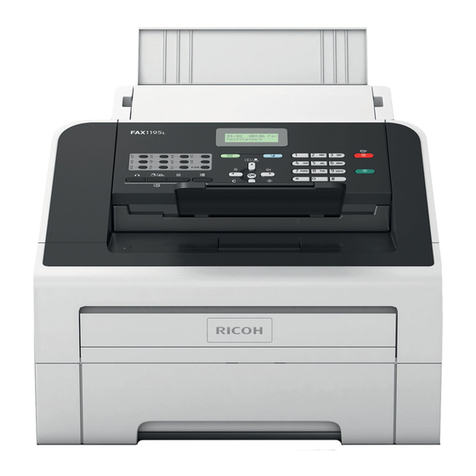
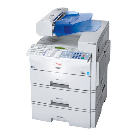
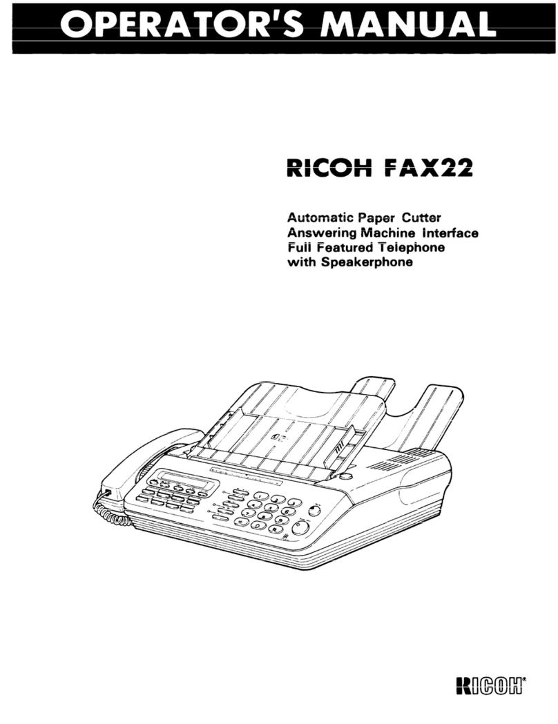
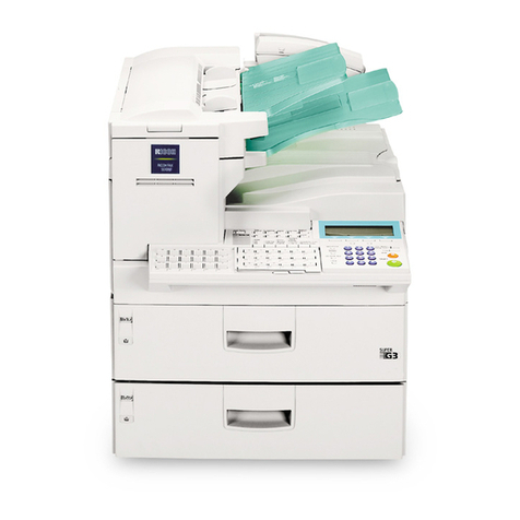
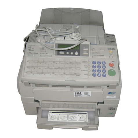
Ricoh FAX550 User manual

FAX550
SERVICE MANUAL

Lithium Batteries (Memory Back-up)
CAUTION:
The danger of explosion exists if a battery of this type is incorrectly replaced.
Replace only with the same or an equivalent type recommended by the
manufacturer. Discard used batteries in accordance with the manufacturer’s
instructions.

CONTENTS
1. OVERALL MACHINE INFORMATION
1.1. SPECIFICATIONS . . . . . . . . . . . . . . . . . . 1-1
1.2. FEATURES . . . . . . . . . . . . . . . . . . . . . 1-2
1.3. COMPONENT LAYOUT . . . . . . . . . . . . . . . . 1-5
1.3.1. Mechanical Components . . . . . . . . . . . . . . 1-5
1.3.2. Drive Components . . . . . . . . . . . . . . . . . 1-6
1.3.3. Electrical Components . . . . . . . . . . . . . . . 1-7
1.4. OVERALL SYSTEM CONTROL . . . . . . . . . . . . . 1-9
1.5. VIDEO DATA PATH . . . . . . . . . . . . . . . . . . 1-10
1.5.1. Transmission . . . . . . . . . . . . . . . . . . . 1-10
1.5.2. Reception . . . . . . . . . . . . . . . . . . . . 1-10
1.6. POWER DISTRIBUTION . . . . . . . . . . . . . . . . 1-11
1.6.1. Distribution Diagram . . . . . . . . . . . . . . . . 1-11
1.6.2. Memory Back-up Circuit . . . . . . . . . . . . . . . 1-12
2. DETAILED SECTION DESCRIPTIONS
2.1. SCANNER . . . . . . . . . . . . . . . . . . . . . . 2-1
2.1.1. Mechanisms . . . . . . . . . . . . . . . . . . . 2-1
1. Document Detection . . . . . . . . . . . . . . . . . 2-1
2. Pick-up and Feed . . . . . . . . . . . . . . . . . . 2-2
2.1.2. Video Data Processing . . . . . . . . . . . . . . . 2-3
2.2. PRINTER . . . . . . . . . . . . . . . . . . . . . . 2-4
2.2.1. Mechanisms . . . . . . . . . . . . . . . . . . . 2-4
1. Paper Feed . . . . . . . . . . . . . . . . . . . . 2-4
2. Cutting . . . . . . . . . . . . . . . . . . . . . . 2-5
3. Cutter Jam Detection . . . . . . . . . . . . . . . . 2-5
2.2.2. Circuits . . . . . . . . . . . . . . . . . . . . . 2-6
1. Video Data Processing . . . . . . . . . . . . . . . . 2-6
2. Thermal Head . . . . . . . . . . . . . . . . . . . 2-6

2.3. PCBs AND THEIR FUNCTIONS . . . . . . . . . . . . . 2-7
2.3.1. FCU . . . . . . . . . . . . . . . . . . . . . . 2-7
2.3.2. MBU . . . . . . . . . . . . . . . . . . . . . . 2-9
2.3.3. SBU . . . . . . . . . . . . . . . . . . . . . . 2-10
2.3.4. OPU . . . . . . . . . . . . . . . . . . . . . . 2-10
2.3.5. NCU . . . . . . . . . . . . . . . . . . . . . . 2-11
2.3.6. PSU . . . . . . . . . . . . . . . . . . . . . . 2-12
3. INSTALLATION
3.1. CONNECTING UP THE MACHINE . . . . . . . . . . . . 3-1
3.2. INITIAL PROGRAMMING . . . . . . . . . . . . . . . 3-2
4. SERVICE TABLES AND PROCEDURES
4.1. SERVICE LEVEL FUNCTIONS . . . . . . . . . . . . . 4-1
4.1.1. Bit Switch Programming (Function 91) . . . . . . . . . 4-1
4.1.2. System Parameter List (Function 92) . . . . . . . . . . 4-1
4.1.3. Error Code Display (Function 93) . . . . . . . . . . . 4-2
4.1.4. Service Monitor (Function 93) . . . . . . . . . . . . . 4-2
4.1.5. Protocol Dump (Function 94) . . . . . . . . . . . . . 4-2
4.1.6. RAM Display/Rewrite (Function 95) . . . . . . . . . . 4-3
4.1.7. RAM Dump (Function 95) . . . . . . . . . . . . . . 4-3
4.1.8. NCU Parameters (Function 96) . . . . . . . . . . . . 4-4
4.1.9. ADF Test (Function 97) . . . . . . . . . . . . . . . 4-4
4.1.10. Xenon Lamp Test (Function 97) . . . . . . . . . . . 4-5
4.1.11. DTMF Tone Test (Function 97) . . . . . . . . . . . . 4-5
4.1.12. Printer Test Patterns (Function 97) . . . . . . . . . . 4-6
4.1.13. Operation Panel Test (Function 97) . . . . . . . . . . 4-6
4.1.14. Modem Test (Function 97) . . . . . . . . . . . . . 4-7
4.1.15. Ringer Test (Function 97) . . . . . . . . . . . . . . 4-8
4.1.16. Buzzer Test (Function 97) . . . . . . . . . . . . . . 4-8
4.1.17. Sensor Initialization (Function 97) . . . . . . . . . . . 4-8
4.1.18. Serial Number (Function 98) . . . . . . . . . . . . . 4-9
4.1.19. Pulse Width (Function 99) . . . . . . . . . . . . . . 4-9
4.1.20. Bypassing Restricted Access . . . . . . . . . . . . 4-10
4.1.21. Printing all Memory Files (Function 24) . . . . . . . . . 4-10
4.2. BIT SWITCHES . . . . . . . . . . . . . . . . . . . . 4-11
4.3. NCU PARAMETERS . . . . . . . . . . . . . . . . . . 4-20
4.4. DEDICATED TRANSMISSION PARAMETERS . . . . . . . 4-27
4.4.1. Programming Procedure . . . . . . . . . . . . . . 4-27
4.4.2. Parameters . . . . . . . . . . . . . . . . . . . . 4-28
4.5. USEFUL RAM ADDRESSES . . . . . . . . . . . . . . 4-30
4.6. SPECIAL TOOLS AND LUBRICANTS . . . . . . . . . . . 4-31
5. REPLACEMENT AND ADJUSTMENT
5.1. COVERS . . . . . . . . . . . . . . . . . . . . . . 5-1
5.1.1. Top Cover . . . . . . . . . . . . . . . . . . . . 5-1
5.1.2. Front and Rear Covers . . . . . . . . . . . . . . . 5-1
5.2. SCANNER . . . . . . . . . . . . . . . . . . . . . . 5-2
5.2.1. ADF Clutch and Pick-up and Feed Rollers . . . . . . . . 5-2
5.2.2. Separation Roller . . . . . . . . . . . . . . . . . 5-3
5.2.3. Tx Motor . . . . . . . . . . . . . . . . . . . . 5-4
5.2.4. Timing Belt Tension Adjustments . . . . . . . . . . . 5-4
5.2.5. Xenon Lamp . . . . . . . . . . . . . . . . . . . 5-5
5.2.6. Xenon Lamp Driver . . . . . . . . . . . . . . . . 5-5
5.2.7. SBU . . . . . . . . . . . . . . . . . . . . . . 5-6
5.2.8. SBU Adjustments . . . . . . . . . . . . . . . . . 5-6
5.3. PRINTER . . . . . . . . . . . . . . . . . . . . . . 5-10
5.3.1. Rx Motor . . . . . . . . . . . . . . . . . . . . 5-10
5.3.2. Thermal Head . . . . . . . . . . . . . . . . . . 5-10
5.3.3. Cutter . . . . . . . . . . . . . . . . . . . . . . 5-11
5.4. PCBs . . . . . . . . . . . . . . . . . . . . . . . . 5-12
5.4.1. FCU and Battery . . . . . . . . . . . . . . . . . 5-12
5.4.2. Memory . . . . . . . . . . . . . . . . . . . . . 5-12
5.4.3. MBU . . . . . . . . . . . . . . . . . . . . . . 5-13
5.4.4. PSU and NCU . . . . . . . . . . . . . . . . . . 5-14
5.4.5. Operation Panel . . . . . . . . . . . . . . . . . . 5-14

6. TROUBLESHOOTING
6.1. COPY QUALITY TROUBLESHOOTING . . . . . . . . . . 6-1
6.1.1. Received Copies . . . . . . . . . . . . . . . . . . 6-1
6.1.2. Copies made in Copy Mode . . . . . . . . . . . . . 6-1
6.2. MECHANICAL PROBLEMS . . . . . . . . . . . . . . . 6-2
6.2.1. ADF/Scanner . . . . . . . . . . . . . . . . . . . 6-2
6.2.2. Printer . . . . . . . . . . . . . . . . . . . . . . 6-5
6.3. ERROR CODES . . . . . . . . . . . . . . . . . . . 6-7
6.4. ELECTRICAL COMPONENT DEFECTS . . . . . . . . . . 6-12
6.4.1. Defective Sensor Table . . . . . . . . . . . . . . . 6-12

1. OVERALL MACHINE INFORMATION
1.1. SPECIFICATIONS
Type
Desktop transceiver
Circuit
PSTN, PABX
Connection
Direct couple
Document Size
Length: 105 - 1200 mm
[4.13 - 47.2 ins]
Up to 100 m [328 ft] after adjustment
Width: 148 - 216 mm
[5.8 - 8.5 ins]
Thickness: 0.05 to 0.15 mm
[2to6mils]
Document Feed
Automatic feed, face down
ADF Capacity
20 sheets (using 20 lb paper)
30 sheets (using 80 g/m2paper)
Scanning Method
Flat bed, with CCD
Maximum Scan Width
216 mm [8.5 ins] ±1%
Scan Resolution
Main scan: 8 dots/mm [203 dpi]
Sub scan:
Standard - 3.85 lines/mm [98 lpi]
Detail - 7.7 lines/mm [196 lpi]
Fine - 15.4 lines/mm [392 lpi]
Memory Capacity
ECM: 128 kbytes (double buffer)
SAF: 256 kbytes (14 pages), with
optional extra 1 Mbyte or 2 Mbytes (max 71
or 128 pages respectively)
Compression
MH, MR, EFC, MMR, SSC
Storage to SAF memory for tx: MH
MMRonly with ECM
Modulation
V.29 (QAM), V.27ter (PHM), V.21 (FM)
Protocol
Group 3 with ECM
Data Rate
9600/7200/4800/2400 bps; automatic fallback
I/O Rate
With ECM: 0 ms/line
Without ECM: 5, 10, 20, or 40 ms/line
Transmission Time
10 s at 9600 bps (G3 ECM using memory)
for a CCITT# 1 test document (Slerexe let-
ter) using standard resolution
Printing System
Thermal printing, automatic cutter
Paper Size
216 mm (A4) x 100 m [8.5 ins x 328 ft]
Maximum Printout Width
210 mm [8.3 ins]
Maximum Printer Resolution
Main scan: 8 dots per mm [203 dpi]
Sub scan: 15.4 lines/mm [392 lpi]
Power Supply
115 ±20 Vac, 60 ±1 Hz
Power Consumption
(Without Optional Kits)
Standby: 13 ±5 W
Transmit: 29 ±5 W
Receive: 22 ±5 W
Copying: 41 ±7 W
Operating Environment
Temperature: 17 - 28 °C [63 - 82 °F]
Humidity: 30 - 85 %Rh
Dimensions (W x D x H)
325 x 388 x 174 mm [12.8 x 15.3 x 6.9 ins]
Excluding handset, trays, and optional units
Weight
10 kg [22 lbs]
1
OVERALL MACHINE INFORMATION November 30th, 1991
SPECIFICATIONS
1-1

1.2. FEATURES
KEY:
O= Used,X= NotUsed,
A = With optional memory only
Equipment
ADF O
Bar code reader X
Built-in handset X
Cabinet X
Connection for ans. machine O
Connection for handset O
Cutter O
Handset O
Hard disk X
Magnetic card reader X
Manual feed mechanism X
Marker X
Microphone X
Monitor speaker O
Remaining memory indicator O
Speakerphone X
Video Processing Features
Contrast O
Halftone (Basic & Error Diffusion) O
MTF O
Reduction O
Resolution O
Smoothing - 8 x 3.85 to 8 x 7.7 O
Smoothing - 8 x 7.7 to 8 x 15.4 X
Communication Features - Auto
Automatic fallback O
Automatic redialing O
Confidential reception A
Dual Access O
Substitute reception O
Transmission Reserve O
Communication Features -
User Selectable
Action as a transfer broadcaster X
AI Redial O
Alternative Destination O
Answering machine O
Authorized Reception O
Auto-answer delay time X
Auto dialing (pulse or DTMF) O
Auto Document O
Automatic Voice Message X
Auto-note X
Batch Transmission (max 5 files) A
Broadcasting O
Chain Dialing O
Confidential ID Override O
Confidential Transmission O
Forwarding (4 stations) A
Free Polling O
Groups (7 groups) O
Hold O
Immediate Redialing O
Immediate transmission O
Keystroke Programs O
Mailbox A
Memory transmission O
Notify X
On Hook Dial O
Page Count O
Personal Codes O
Personal Codes with Conf ID A
Polling Reception O
Polling Transmission O
Quick Dial (30)
Reception modes (Fax, Tel, Auto) O
Reduction X
Remote control features O
Remote Transfer O
Restricted Access (10 codes,
without cards) O
Secured Polling O
Secured Polling with Stored ID
Override O
Send Later O
Silent ringing detection O
November 30th, 1991 OVERALL MACHINE INFORMATION
FEATURES
1-2

Communication Features -
User Selectable
Speed Dial (100)
Telephone Directory O
Tonal Signal Transmission O
Transfer Request: 30 stations O
Transmission Deadline X
Turnaround Polling X
Voice Request O
Communication Features -
Service Selectable
AI Short Protocol X
Auto-reduction override option X
Busy tone detection O
Closed network (tx and rx) O
Continuous Polling Reception O
Dedicated tx parameters O
ECM O
EFC O
MV1200 compatibility X
Page retransmission O
Page separation mark X
Polling tx file lifetime in the SAF O
Protection against wrong conn. O
Resol’n stepdown override option X
Short Preamble O
Well log O
Other User Features
Auto Service Call X
Center mark X
Checkered mark X
Clearing a memory file O
Clearing a polling file O
Clock O
Confidential ID A
Copy mode O
Counters O
Dialed number check X
Direct entry of names O
Function Programs O
ID Code O
Label Insertion O
Language Selection O
LCD contrast control Service
Memory Lock A
Memory Lock ID A
Modifying a memory file X
Multi Sort Document Reception X
Multicopy mode X
Night Timer X
Own telephone number O
Printing a memory file O
RDS on/off O
Reception Mode Switching Timer O
Reception Time (non-memory rx
only) O
Remote ID O
Reverse Order Printing X
RTI, TTI, CSI O
Speaker volume control O
Specified Cassette Selection X
Substitute reception on/off O
Telephone line type O
TTI on/off O
User Function Keys X
User Parameters O
Wild Cards O
Reports - Automatic
Charge Control Report X
Communication Failure Report O
Confidential File Report A
Error Report O
Memory Storage Report O
Mode Change Report X
Polling Clear Report O
Polling Reserve Report O
Polling Result Report O
Power Failure Report O
TCR O
Transfer Result Report X
Transmission Result Report O
Reports - User-initiated
Authorized Reception List O
Charge Control Report X
File List O
Forwarding List A
Group List O
Personal Code List O
Program List O
Quick Dial List O
1
OVERALL MACHINE INFORMATION November 30th, 1991
FEATURES
1-3

Reports - User-initiated
Specified Cassette Selection List X
Speed Dial List O
TCR O
Transmission Status Report X
User Function List X
User Parameter List O
Service Mode Features
Back-to-back test O
Bit switch programming O
Buzzer test O
Cable equalizer (rx only) O
Comm. parameter display O
DTMF tone test O
Echo countermeasure O
Error code display O
LCD contrast control O
Memory file forwarding O
Memory file printout (all files) O
Modem test O
NCU parameters O
Operation panel test O
Printer mechanism test X
Printer test patterns O
Programmable attenuation X
Protocol dump list O
RAM display/rewrite O
RAM dump O
Ringer test X
Scanner lamp test O
Scanner mechanism test O
Sensor initialization O
Serial number programming O
Service monitor report O
Service station number X
System parameter list O
Technical data on the TCR O
Thermal head parameters O
Transmission Status Report X
Memory Files
Max. number of files: 100
Max. number of stations/file: 142
Max. number of stations overall: 299
Max. number of pages overall: 200
(including pages stored as Auto
Documents)
November 30th, 1991 OVERALL MACHINE INFORMATION
FEATURES
1-4

1.3. COMPONENT LAYOUT
1.3.1. Mechanical Components
1. R2 Rollers Feed the document through the scanner.
2. Exposure Glass Exposes the original to light from the xenon lamp.
3. Xenon Lamp Illuminates the document.
4. R1 Rollers Feed the document through the scanner.
5. Separation Roller Allows one page into the scanner.
6. Document Feed Roller Feeds the document into the scanner.
7. Separation Plate Spreads out the leading edges of the pages fed into the
scanner.
8. Pick-up Roller Picks up pages of the document from the document
table.
9. Lens Block Focuses light reflected from the document onto the
CCD.
10. CCD (Charge Coupled
Device) This converts the light reflected from the document into
an analog video signal.
11. Thermal Paper Roll Thermal paper for printing.
12. Shading Plate Allows more light through from the ends of the xenon
lamp than from the center, to counteract the relative
dimness at the ends of the lamp.
13. Second Mirror Reflects light from the document towards the CCD.
14. Thermal Head Prints received data on the thermal paper.
15. Platen Roller Feeds the paper through the printer.
16. Cutter Cuts off the printed page.
17. Feed-out Rollers Feed out the page which has been cut off.
18. First Mirror Reflects light from the document towards the CCD.
19. Third Mirror Reflects light from the document towards the CCD.
123456 78 9 10 11
121317 16 15 14
19
18
1
OVERALL MACHINE INFORMATION November 30th, 1991
COMPONENT LAYOUT
1-5

1.3.2. Drive Components
1. R2 Roller Drive Gear Drives the R2 roller.
2. Scanner Drive Gear Transfers drive from the Tx motor to the
scanner and ADF.
3. R1 Roller Drive Gear Drives the R1 roller.
4. Document Feed Idle
Gear Transfers drive from the Tx motor to the
document feed roller.
5. ADF
Clutch/Document
Feed Drive Gear
Drive the document feed roller, which feeds
the document into the scanner.
6. Tx Motor Drives the ADF and scanner.
7. Rx Motor Drives the printer.
8. Printer Drive Gears Transfer Rx motor drive to the printer.
9. Platen Roller Drive
Gear Drives the platen roller, which pulls the
thermal paper through the printer
10. Feed-out Roller Drive
Gear Drives the feed-out roller, which feeds the
printed copy out of the machine.
12 34 5 6
7
8
9
10
November 30th, 1991 OVERALL MACHINE INFORMATION
COMPONENT LAYOUT
1-6

1.3.3. Electrical Components
Name Description No.
PCBs
FCU This board controls the machine. 11
MBU This board contains the system ROM and RAM
for storing system parameters such as bit switch
settings and programmed telephone numbers.
8
SBU This board contains the CCD. 10
OP-PORT This board controls the operation panel. 23
NCU This board contains relays and switches for
interfacing the machine to the telephone network
and the handset.
4
PSU This board supplies power to the machine. 7
Xenon Lamp
Driver This supplies power to the xenon lamp. 14
MOTORS
Tx Motor This drives the scanner. 5
Rx Motor This drives the printer. 6
Cutter Motor This drives the cutter. 1
1
2
3
4
5
6
7
8
9
10
11
22 23
15
16
17
18
19
20 21
12
13
14
1
OVERALL MACHINE INFORMATION November 30th, 1991
COMPONENT LAYOUT
1-7

Name Description No.
CLUTCHES
ADF Clutch This transfers drive from the tx motor to the
document feed roller. 3
SENSORS
Document Sensor This detects the presence of a document in the
feeder. 22
Scan Line Sensor This detects when a page is approaching the
auto shading position. 21
Trailing Edge Sen-
sor This detects when the trailing edge of the page is
passing the scan line. 20
Paper End Sensor This detects when the thermal paper has run out. 16
Printer Jam Sen-
sor This detects jams in the printer. 18
Cutter Sensor This monitors the operation of the cutter. 2
Cover Switch This detects whether the cover is open or closed. 15
OTHERS
Thermal Head This prints on the thermal paper. 17
SAF Memory Mod-
ules These memory modules each contain 1 Mbyte of
memory for storing fax messages. 9
Speaker This allows the user to listen to the condition of
the telephone line. 12
Xenon Lamp This lamp illuminates the document. 19
Battery This rechargeable battery backs up the SAF
memory when the main power is switched off. 13
November 30th, 1991 OVERALL MACHINE INFORMATION
COMPONENT LAYOUT
1-8

1.4. OVERALL SYSTEM CONTROL
The cpu on the FCU board controls the machine, as shown in the above
drawing.
There is no modem board in the machine. The cpu performs the digital func-
tions of a modem and carries out digital to analog conversion of facsimile
data. There is a separate analog modem chip (called the Modem AFE) which
does the rest of the modem operations.
DATA AND ADDRESS BUS
Scanner
Sensors
CONTROL SIGNALS
Scanner and Printer Drive
Components and Sensors
ECM
Memory
SAF
Memory
RAMROM
Thermal
Head
Video Processing
Memory
Video
Processor
SBU
(CCD)
Operation
Panel
PSU
HandsetLine
NCU Speaker
I/O
Port
CPU
MBU
FCU
RS-232C
Interface
Modem AFE
1
OVERALL MACHINE INFORMATION November 30th, 1991
OVERALL SYSTEM CONTROL
1-9

1.5. VIDEO DATA PATH
1.5.1. Transmission
1.5.2. Reception
The following diagrams show
the data path for this model.
Line
Buffer FIFO
RAM
Analog Signal
Original
CCD
SAF
Memory
ECM
Memory Video
Processor
MBU To the
Network
(via the NCU)
Xenon
Lamp
FCU
CPU
Modem
(Analog)
Modem
(Digital)
MODEM
AFE
There is no pro-
grammable resis-
tor in this model.
Reference:
Group 3
Facsimile
Manual,
section 1-3-1
Line
Buffer FIFO
RAM
SAF
Memory ECM
Memory
Modem
(Analog)
CPU
Modem
(Digital)
Filter
MBU
From the
Network
(via the NCU)
FCU
Thermal
Head
Thermal
Paper
I/O Port
HYBRID IC
MODEM
AFE
Reference:
Group 3
Facsimile
Manual,
section
1-3-2
November 30th, 1991 OVERALL MACHINE INFORMATION
VIDEO DATA PATH
1-10

1.6. POWER DISTRIBUTION
1.6.1. Distribution Diagram
The PSU supplies power to the machine through the FCU, except for the ther-
mal head power, which it supplies directly. The FCU contains regulators
which generate other voltages needed by the machine.
There are two + 24V power supplies:
•+ 24VS: This is always on when the main switch is on.
•+ 24VD: This is switched on by the cpu when a ringing signal is de-
tected, or when the user presses the Start or Copy key. It is not inter-
rupted if the cover switch is opened; however, printing stops and the
document is fed out.
In some documentation for this model, + 24VD may sometimes be referred
to as + 24VA.
+24VD
PSU
Regulator
Regulator
+5V
+24VS
+24VD
-12V
+5V
+12V
+24VS
+24VD
- 5V
- 12V
FCU
OPU
+5V
SBU
+5V
+12V
+5V
Scanner
Sensors
Printer
Sensors
NCU
+5V
+24VS
+5V RS-232C
Interface
Thermal
Head +5V
+24VD
+5V MBU
+5V
Motors, ADF Clutch
Xenon Lamp
1
OVERALL MACHINE INFORMATION November 30th, 1991
POWER DISTRIBUTION
1-11

1.6.2. Memory Back-up Circuit
The battery [A] on the MBU backs up the RAM on the MBU, which contains
system parameters. It also backs up the real time clock in the cpu. This bat-
tery is not rechargeable. CN1-9 tells the cpu whether the back-up power
(CN1-11) comes from the battery or from the + 5V supply.
A rechargeable battery [B] backs up the SAF memory and the real time clock
for 1 hour. When the main power is switched on, the + 24V supply charges
the battery. If there is data in the SAF, the battery also backs up the real time
clock, to preserve the MBU battery.
Battery
+5V
Regulator
SAF
Memory
+24V
Battery
Switch
Battery
+5V
Voltage
Detector
Switching
Circuit
RAM
CPU
Memory
Monitor
1-11 1-11
1-9 1-9
MBU FCU
Real Time
Clock
5-1
Switching
Circuit
5-2
[A]
[B]
Reference:
Group 3
Facsimile
Manual,
section 1-4-3
(Circuit type 1)
November 30th, 1991 OVERALL MACHINE INFORMATION
POWER DISTRIBUTION
1-12

2. DETAILED SECTION DESCRIPTIONS
2.1. SCANNER
2.1.1. Mechanisms
1. Document Detection
•The machines in this series have an A4-width [8.3"] scanner. There is
no document width detector.
•The scanner contains a xenon lamp.
•There is no shutter mechanism.
Reference: Group 3 Facsimile Manual, section 2-1.
ADF Clutch
Scan Line Sensor
Document
Sensor
Separation
Plate
Pick-up Roller
Separation Roller
Feed
Roller
Trailing Edge
Sensor
2
DETAILED SECTION DESCRIPTIONS November 30th, 1991
SCANNER
2-1

2. Pick-up and Feed
Mechanism
•This machine uses an electrical clutch mechanism with trailing edge sen-
sor.
•There is no manual feed.
Resolution
Standard - The tx motor feeds the document at 7.7 lines/mm. The video
processor executes OR processing to convert the data into 3.85 lines/mm.
Detail - The tx motor feeds the document at 7.7 lines/mm. There is no OR
processing, and the data is transmitted at 7.7 lines/mm
Fine - The tx motor feeds the document and transmits data at 15.4 lines/mm.
If the other terminal cannot receive at this resolution, the tx motor feeds the
paper at 7.7 lines/mm, and the data is transmitted using Detail resolution.
Jam Conditions
The cpu detects a document jam if one of the following conditions occurs.
•The scan line sensor does not switch on within 3.5 s of the Start key be-
ing pressed.
•The scan line sensor does not turn off after the maximum document
length has been fed since it turned on.
•The scan line sensor switches on while the document sensor is off.
Tx Motor ADF Clutch
Reference:
Group 3
Facsimile
Manual,
section 2-2
November 30th, 1991 DETAILED SECTION DESCRIPTIONS
SCANNER
2-2
This manual suits for next models
1
Table of contents
Other Ricoh Fax Machine manuals

Ricoh
Ricoh FAX 3320L User manual

Ricoh
Ricoh FAX 2900Li User manual

Ricoh
Ricoh 3245 User manual

Ricoh
Ricoh FAX2900L User manual

Ricoh
Ricoh 1195L Operating and maintenance manual

Ricoh
Ricoh Fax 680 MP User manual

Ricoh
Ricoh 4430NF User manual

Ricoh
Ricoh FAX220 User manual

Ricoh
Ricoh FAX2900L User manual

Ricoh
Ricoh FAX1180L User manual

Ricoh
Ricoh Aficio SP C231SF Owner's manual

Ricoh
Ricoh FAX2500L User manual

Ricoh
Ricoh Aficio 2022 User instructions

Ricoh
Ricoh FAX3700l User manual

Ricoh
Ricoh 3900L User manual

Ricoh
Ricoh MV310E User manual

Ricoh
Ricoh FAX1400L Owner's manual

Ricoh
Ricoh 5510L User manual

Ricoh
Ricoh Fax 2210L User manual

Ricoh
Ricoh FAX1180L Installation instructions