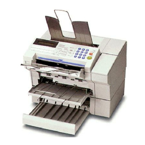
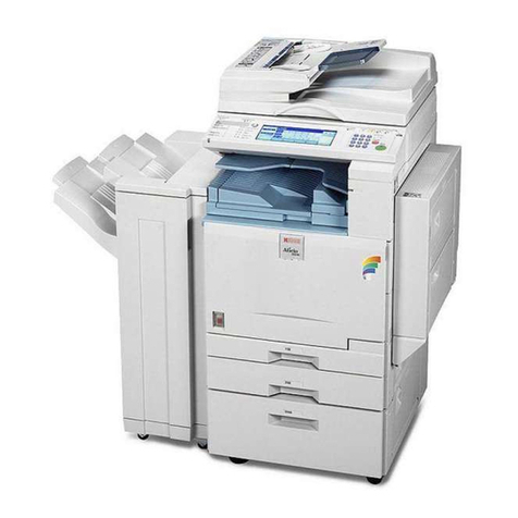
Ricoh FT5233 User manual

FT5233/5433/5733
SERVICE MANUAL

IMPORTANT SAFETY NOTICES
PREVENTION OF PHYSICAL INJURY
1. Before disassembling or assembling parts of the copier and peripherals,
make sure that the copier power cord is unplugged.
2. The wall outlet should be near the copier and easily accessible.
3. Note that some components of the copier and the paper tray unit are
supplied with electrical voltage even if the main switch is turned off.
4. If any adjustment or operation check has to be made with exterior covers
off or open while the main switch is turned on, keep hands away from
electrified or mechanically driven components.
5. If the hot roller temperature is low when the main switch is turned on, the
copier starts idling automatically when the warm-up period is completed.
Keep hands away from the mechanical and the electrical components to
avoid any injury.
6. If the start key is pressed before the copier completes the warm-up period
(Ready indicator starts blinking), keep hands away from the mechanical
and the electrical components as the copier starts making copies as soon
as the warm-up period is completed.
7. The inside and the metal parts of the fusing unit become extremely hot
while the copier is operating. Be careful to avoid touching those
components with your bare hands.
HEALTH SAFETY CONDITIONS
1. Never operate the copier without the ozone filters installed.
2. Always replace the ozone filters with the specified ones at the specified
intervals.
3. Toner and developer are non-toxic, but if you get either of them in your
eyes by accident, it may cause temporary eye discomfort. Try to remove
with eye drops or flush with water as first aid. If unsuccessful, get medical
attention.
OBSERVANCE OF ELECTRICAL SAFETY STANDARDS
1. The copier and its peripherals must be installed and maintained by a
customer service representative who has completed the training course
on those models.
2. The RAM board on the main control board has a lithium battery which can
explode if replaced incorrectly. Replace the battery only with an identical
one. The manufacturer recommends replacing the entire RAM board. Do
not recharge or burn this battery. Used batteries must be handled in
accordance with local regulations.
SAFETY AND ECOLOGICAL NOTES FOR DISPOSAL
1. Do not incinerate the toner cartridge or the used toner. Toner dust may
ignite suddenly when exposed to open flame.
2. Dispose of used toner, developer, and organic photoconductor according
to local regulations. (These are non-toxic supplies.)
3. Dispose of replaced parts in accordance with local regulations.
4. When keeping used lithium batteries in order to dispose of them later, do
not put more than 100 batteries per sealed box. Storing larger numbers or
not sealing them apart may lead to chemical reactions and heat build-up.

SECTION 1
OVERALL MACHINE
INFORMATION

1. SPECIFICATIONS
Configuration: Desktop
Copy Process: Dry electrostatic transfer system
Originals: Sheet/Book
Original Size: MaximumA3/11" x 17"
Copy Paper Size: MaximumA3/11" x 17"
Minimum B5/11" x 81/2" - Paper tray
A6/51/2" x 81/2" (lengthwise)
-By-pass feed table
(LCT B5/A4/11" x 81/2" sideways only)
(Duplex Copying)
Multiple:
Single/Overlay: A4 and B5/81/2" x 11" (sideways)
Maximum A3/11" x 17"
Minimum B5/8" x 13"
Copy Paper Weight: •250-sheet paper tray and 1000-sheet large
capacity tray:
52 –128g/m2, 14 –34lb
•By-pass feed table:
52 –157g/m2, 14 –43lb
•Duplex and overlay:
64 –105 g/m2, 17 –28lb
Reproduction Ratios: 4 Enlargement and 6 Reduction
A4/A3 Version LT/LDG Version
Enlargement
200%
141%
122%
115%
200%
155%
129%
121%
Full Size 100% 100%
Reduction
93%
82%
75%
71%
65%
50%
93%
85%
77%
74%
65%
50%
Receiving Tray
Capacity: 250 sheets (B4/81/2" x 14" and smaller)
100 sheets (A3/11" x 17")
Overall
Information
12 February 1992 SPECIFICATIONS
1-1

Power Source: 115V, 60HZ, more than 12A (for N.A)
110V, 60HZ, (for Taiwan)
220/230/240V, 50HZ/60HZ, more than 7A
(for EU and AA)
Power Consumption: Maximum: 1.5 KW
Warm-up: 0.77 KW
Stand-by: 0.14 KW
Copy Cycle (average): 1.2 KW
Noise Emission: Stand-by: less than 40 dB
Copy Cycle (average):
less than 57 dB (copier only)
less than 59 dB (full system)
Maximum:
less than 62 dB (copier only)
less than 63 dB (full system)
Dimensions: Width Depth Height
Type 1 697 mm (1035 mm)
27.4" (40.7") 600 mm
23.6" 542 mm (574 mm)
21.3" (22.6")
Type 2 871 mm (1075 mm)
34.3" (42.2") 600 mm
23.6" 542 mm (574 mm)
21.3" (22.6")
Type 3 871 mm (1075 mm)
34.3" (42.2") 600 mm
23.6" 542 mm (574 mm)
21.3" (22.6")
( ): When the by-pass feed table is opened, the copy tray is extended, and
the platen cover is installed.
Weight: Copier only (Without the optional platen
cover=Approximately 2 kg)
Type 1: approximately 78 kg (172.0 lb)
Type 2: approximately 88 kg (194.0 lb)
Type 3: approximately 84 kg (185.2 lb)
Zoom: From 50% to 200% in 1% steps
Copying Speed: 33 copies/minute (A4/81/2" x 11" sideways)
19 copies/minute (A3)
18 copies/minute (11" x 17")
Warm-up Time: Less than 110 seconds (20°C)
SPECIFICATIONS 12 February 1992
1-2

First Copy Time: Black copy:
4.5 seconds (A4/81/2" x 11" sideways)
Type 1, 3: (Upper tray feed)
4.9 seconds
Type 2: (Large capacity tray feed)
Color copy:
6.6 seconds
Type 1, 3: (Upper tray feed)
7.0 seconds
Type 2: (Large capacity tray feed)
Copy Number Input: Ten keys, 1 to 999 (count up or count down)
manual Image Density
Selection: 7 steps
Automatic Reset: 1 minute standard setting; can also be set to 3
minutes or no auto reset.
Copy Paper Capacity: •By-pass feed table; approximately 20 sheets
•Paper tray: approximately 250 sheets
•Large capacity tray; approximately 1000 sheets
Toner Replenishment: Black: cartridge exchange
(320 g/cartridge)
Color: manual exchange (red, blue, & green
60 g/cartridge)
Optional Equipment: •Platen cover
•Document feeder
•Paper tray unit with one paper tray
•Paper tray unit with three paper trays
•10 bin micro sorter
•20 bin mini sorter
•20 bin midi sorter
•20 bin sorter stapler
•Sorter adapter (needed when installing the
mini or midi sorter, or the sorter stapler)
•Interface PCB (needed when installing the
sorter stapler or the menu reader)
•Editor (only for A074)
•Editing interface adapter (needed when
installing the editor)
Overall
Information
12 February 1992 SPECIFICATIONS
1-3

•Color development unit
•Key counter
•Menu reader (except for Europe)
•A3 counter (service part)
SPECIFICATIONS 12 February 1992
1-4

2. MACHINE CONFIGURATION
2.1 COPIER
TYPE 1 (A069) TYPE 2 (A074) TYPE 3 (A073)
UPPER TRAY 250 DUPLEX 250
LOWER TRAY 250 250 250
LCT – 1,000 1,000
2.2 OPTIONAL EQUIPMENT EDITOR (A916)
ARDF (A497)
MENU READER (A952)
20BIN SORTER
(A411)
20BIN SORTER
(A423)
SORTER STAPLER
(A366)
SORTER ADAPTER
(A328)
10BIN SORTER (A327)
PAPER TRAY UNIT PAPER TRAY UNIT
(A325) (A326)
Overall
Information
12 February 1992 MACHINE CONFIGURATION
1-5

COPIER REQUIRED OPTIONAL
EQUIPMENT
PAPER
TRAY UNIT
1 TRAY
(A325) TYPE 1
(A069) TYPE 2
(A074) TYPE3
(A073)
SORTER
ADAPTER
(A328)
INTERFACE
PCB
(A344)
EDITING
INTERFACE
ADAPTER
(A345)
3 TRAY
(A326) ooo
SORTER
10 BIN
(A327) ooo
20 BIN MINI
(A423) ooo *
20 BIN MIDI
(A411) ooo *
20 BIN
STAPLER
(A366) ooo * **
DOCUMENT
FEEDER ARDF
(A497) ooo
EDITOR (A916) x o x * **
MENU READER (A952) o o o **
COLOR DEVELOPMENT
UNIT (A337) ooo
NOTE1: * The sorter adapter is required to install the 20 bin
mini sorter, 20 bin midi sorter or sorter stapler.
* * The I/F board is required to install the sorter stapler
or Menu Reader.
** * (1) The editing interface adapter is required to install
the editor.
(2) The editing interface adapter can be installed
independently when more precise erasing is
desired.
NOTE 2: When installing the sorter stapler, the copier must be placed
on the paper tray unit or a table of exactly the same height.
MACHINE CONFIGURATION 12 February 1992
1-6

3. COPY PROCESS AROUND THE DRUM
2. EXPOSURE
1. DRUM
CHARGE
9. QUENCHING
8. CLEANING
ID/V SENSORS
PICK-OFF
PAWLS
7. PAPER
SEPARATION 6. IMAGE TRANSFER
5. PRE-TRANSFER
LAMP
4. DEVELOPMENT
(COLOR)
4. DEVELOPMENT
(BLACK)
3. ERASE
Overall
Information
12 February 1992 COPY PROCESS AROUND THE DRUM
1-7

1. DRUM CHARGE
In the dark, the charge corona unit gives a uniform negative charge to the
organic photo conductive (OPC) drum. The charge remains on the surface of
the drum because the OPC layer has a high electrical resistance in the dark.
The amount of negative charge on the drum is proportional to the negative
grid bias voltage applied to the grid plate on the charge corona unit.
2. EXPOSURE
An image of the original is reflected to the OPC drum surface via the optics
assembly. The charge on the drum surface is dissipated in direct proportion
to the intensity of the reflected light, thus producing an electrical latent image
on the drum surface.
The amount of remaining charge as a latent image on the drum depends on
exposure lamp intensity controlled by the exposure lamp voltage.
3. ERASE
The erase lamp illuminates the areas of the charged drum surface that will
not be used for the copy image. The resistance of the drum in the illuminated
areas drops and the charge on those areas dissipates.
4. DEVELOPMENT
Positively charged toner is attracted to the negatively charged areas of the
drum, thus developing the latent image. (The positive triboelectric charge is
caused by friction between the carrier and toner particles.)
The development bias voltage applied to the development roller shaft
controls two things:
1) The threshold level if toner is attracted to the drum or toner remains on
the development roller.
2) The amount of toner to be attracted to the drum.
The higher the negative development bias voltage is, the less toner is
attracted to the drum surface.
5. PRE-TRANSFER LAMP (PTL)
The PTL illuminates the drum to remove almost all the negative charge from
the exposed areas of the drum. This prevents the toner particles from being
reattracted to the drum surface during paper separation and makes paper
separation easier.
COPY PROCESS AROUND THE DRUM 12 February 1992
1-8

6. IMAGE TRANSFER
Paper is fed to the drum surface at the proper timing so as to align the copy
paper and the developed image on the drum surface. Then, a strong
negative charge is applied to the reverse side of the copy paper, producing
an electrical force which pulls the toner particles from the drum surface onto
the copy paper. At the same time, the copy paper is electrically attracted to
the drum surface.
7. PAPER SEPARATION
A strong ac corona discharge is applied to the reverse side of the copy
paper, reducing the negative charge on the copy paper and breaking the
electrical attraction between the paper and the drum. Then, the stiffness and
the weight of the copy paper causes it to separate from the drum surface.
The pick-off pawls help to separate paper and drum.
8. CLEANING
The cleaning brush removes toner remaining on the drum after image
transfer and the cleaning blade scrapes off all the remaining toner.
9. QUENCHING
Light from the quenching lamp electrically neutralizes the charge potential of
the drum surface.
Overall
Information
12 February 1992 COPY PROCESS AROUND THE DRUM
1-9

4. MECHANICAL COMPONENT LAYOUT
42
41
42
40
39
38
37
36
35
34
33 32 31 30 29 28 27 26 25 24 23
22
21
20
19
18
17
16
15
14
13
12
111098765
4
3
2
1
1. 3rd Mirror
2. 2nd Mirror
3. 1st Mirror
4. Exposure Lamp
5. Lens
6. Cleaning Brush
7. Quenching Lamp
8. Cleaning Blade
9. Change Corona Unit
10. OPC Drum
11. 6th Mirror
12. Erase Unit
13. 4th Mirror
14. 5th Mirror
15. Color Development Unit
16. Black Development Unit
17. Black Toner Supply Unit
18. Pre-Transfer Lamp
19. Feed Roller
20. Pick-up Roller
21. Separation Roller
22. Large Capacity Tray
23. Relay Rollers
24. Registration Rollers
25. Paper Tray Feed Roller
26. Friction Pad
27. Turn Gate
28. Duplex Friction Roller
29. Duplex Feed Roller
30. Transfer & Separation Corona Unit
31. Jogger Fences
32. End Fence
33. Lower Paper Tray
34. Entrance Rollers
35. Duplex Tray
36. Pressure Roller
37. Pick-off Pawls
38. Hot Roller
39. Junction Gate
40. Hot Roller Strippers
41. Transport Fan
42. Fusing Exhaust Fan
MECHANICAL COMPONENT LAYOUT 12 February 1992
1-10

5. DRIVE LAYOUT
1
2
1
3
4
98
7
6
5
10
11
12
13
14
1015
16
17
18
19
20
21
22
26
25
24
23
Overall
Information
12 February 1992 DRIVE LAYOUT
1-11

26: Development Drive
Belt
1: Main Motor Pulley
3: Fusing Drive Belt 2: Drum Drive Belt
4: Drive Distribution
Gear/Pulley 25: Drum Drive Pulley 24: Development Drive
CL Pulley
Drum Development Unit
23: Drive Distribution Belt Cleaning drive Gear 9: Fusing Unit Drive
Gear
Cleaning Unit Fusing Unit
12: Drive Distribution
Gear/Pulley 20: Toner Supply
Drive Gear/Pulley 6: Copier Exit
Roller Gear
22: Toner Supply CL
Gear
21: Development Unit
Shift Gears
7: Duplex Transport
Drive Belt
8: Duplex Transport
Roller Pulley
5: Sorter Adapter Gears
10: Registration CL Gear
11: Upper Paper Feed CL
13: Feed Relay CL Gear
17: Relay Roller Gears
19: Paper Feed Drive
Gear/Pulley
16: Paper Feed Drive
Belt
14: Lower paper Feed
CL Gear 15: Tray Unit drive
Gear
18: By-pass Feed CL
Gear
DRIVE LAYOUT 12 February 1992
1-12

6. PAPER PATH
6.1 NORMAL COPYING
Paper feed begins from the LCT or paper tray unit paper feed stations. The
copy paper then follows one of two paths inside the copier. The path followed
depends on which mode the operator has selected. For copy processing, all
sheets follow the same path from the paper feed mechanism [A] through the
registration [B], T & S corona [C], and fusing unit [D]. After that, normal
copies are delivered to the copy tray [E], however, 2 sided copies and
overlay copies are diverted for further processing.
[D] [C] [B]
[A]
[A]
[E]
Overall
Information
12 February 1992 PAPER PATH
1-13

6.2 MULTIPLE 2-SIDED COPYING
Paper that is A4, B5, and 81/2" X 11" sideways can be used for multiple
2-sided copying. In this mode the junction gate [A] directs sheets exiting the
fusing unit to the duplex tray entrance [B]. After that, all sheets follow the path
through the entrance rollers [C], and the turn gate [D]. The turn gate directs
paper through the duplex feed mechanism [E] to the duplex tray [F]. After all
sheets are stacked in the duplex tray, these sheets follow the path through
the duplex feed mechanism and relay rollers [G] to the registration rollers [H].
After that, these sheets follow the same path as normal copying from the
registration rollers to the copy tray.
[H]
[G]
[D]
[E]
[F]
[C]
[A]
[B]
PAPER PATH 12 February 1992
1-14

6.3 SINGLE 2-SIDED COPYING
Any sheet up to A3\11" x 17" but except for A4, B5, or 81/2" X 11" sideways
can be used for single 2-sided copying. In this mode, the sheet follows the
same path as in multiple 2-sided copying to the duplex tray. However, the
end fence [A] of the duplex tray lowers. The sheet advances over the lowered
end fence. The sheet is stopped by the friction between the duplex feed and
friction rollers [B,C]. It is directed to the relay rollers [D] by the reversed
duplex feed roller. It stays there once. After that, the sheet follows the same
path as in multiple 2-sided copying from the relay rollers to copy tray.
[D]
[B]
[C]
[A]
Overall
Information
12 February 1992 PAPER PATH
1-15

6.4 SINGLE IMAGE OVERLAY COPYING
In this mode, the sheet follows the same path as in multiple 2-sided copying
to the turn gate [A]. The turn gate directs the sheet to the relay rollers [B].
The sheet stays there once. After that, the sheet follows the same path as in
multiple 2-sided copying from the relay rollers to the copy tray.
[B]
[A]
PAPER PATH 12 February 1992
1-16
This manual suits for next models
2
Table of contents
Other Ricoh Fax Machine manuals

Ricoh
Ricoh 1195L User manual

Ricoh
Ricoh 1232 Series User manual

Ricoh
Ricoh 2000 User manual

Ricoh
Ricoh Aficio 2022 User instructions

Ricoh
Ricoh FAX07 Quick start guide

Ricoh
Ricoh 1000L Quick start guide

Ricoh
Ricoh FAX4800L User manual

Ricoh
Ricoh Fax 680 MP User manual

Ricoh
Ricoh FAX1400L Owner's manual

Ricoh
Ricoh FAX550 User manual

Ricoh
Ricoh FAX 1190L User manual

Ricoh
Ricoh FAX4430NF Operating instructions

Ricoh
Ricoh B383 User manual

Ricoh
Ricoh MV310E User manual

Ricoh
Ricoh 4420NF User manual

Ricoh
Ricoh FAX2500L User manual

Ricoh
Ricoh SMFC210M SecureFax User manual

Ricoh
Ricoh Aficio 1018 User manual

Ricoh
Ricoh FAX RF01F User manual

Ricoh
Ricoh LASER FACSIMILE User manual