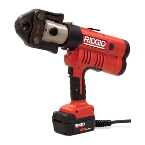
RIDGID RP 342-XL User manual

RP 342-XL Press Tool
•Français – 13
•Castellano – pág. 27
Press Tool Manual

999-999-207.10_REV. A
ii
RP 342-XL Press Tool
Table of Contents
Recording Form For Machine Serial Number ............................................................................................................1
Safety Symbols..............................................................................................................................................................2
General Power Tool Safety Warnings
Work Area Safety........................................................................................................................................................2
Electrical Safety ..........................................................................................................................................................2
Personal Safety ..........................................................................................................................................................3
Power Tool Use And Care ..........................................................................................................................................3
Battery Tool Use And Care ........................................................................................................................................3
Service ........................................................................................................................................................................4
Specific Safety Information
Press Tool Safety........................................................................................................................................................4
RIDGID®Contact Information ......................................................................................................................................4
Description
Tool Status Lights ......................................................................................................................................................6
Specifications
Standard Equipment ..................................................................................................................................................6
Pre-Operation Inspection ............................................................................................................................................7
Set-Up And Operating Instructions ............................................................................................................................7
Removing/ nstalling Attachment ................................................................................................................................7
Changing Tool Configuration (“Extended”/“Standard”) ..............................................................................................8
Preparing Connection ................................................................................................................................................8
Pressing A Fitting With Typical Scissor Jaws ............................................................................................................9
Pressing A Fitting With Typical Actuator And Press Ring Set ....................................................................................9
nspecting The Pressed Connection ........................................................................................................................10
Storage ........................................................................................................................................................................10
Maintenance Instructions
Cleaning And Lubrication..........................................................................................................................................10
Troubleshooting ........................................................................................................................................................11
Required Maintenance By R DG D Authorized ndependent Service Center ..........................................................10
Service And Repair ..................................................................................................................................................10
Optional Equipment ....................................................................................................................................................10
Disposal ......................................................................................................................................................................11
EC Declaration of Conformity ....................................................................................................................................11
Electromagnetic Compatibility (EMC) ......................................................................................................................11
Lifetime Warranty ........................................................................................................................................Back Cover
*Original nstructions - English

RP 342-XL Press Tool
Record Serial Number below and retain product serial number which is located on nameplate.
Serial
No.
Press Tool
RP 342-XL
WARNING!
Read this Operator’s Manual
carefully before usin this
tool. Failure to understand
and follow the contents of
this manual may result in
electrical shock, fire and/or
serious personal injury.

999-999-207.10_REV. A
2
RP 342-XL Press Tool
General Power Tool Safety
Warnings*
WARNING
Read all safety warnings and instructions. Failure
to follow the warnings and instructions may result
in electric shock, fire and/or serious injury.
SA E ALL WARNINGS AND INSTRUCTIONS
FOR FUTURE REFERENCE!
The term "power tool" in the warnings refers to your
mains-operated (corded) power tool or battery-operated
(cordless) power tool.
Work Area Safety
•Keep your work area clean and well lit. Cluttered or
dark areas invite accidents.
•Do not operate power tools in explosive atmo-
spheres, such as in the presence of flam mable
liquids, gases, or dust. Power tools create sparks
which may ignite the dust or fumes.
•Keep children and by-standers away while oper-
ating a power tool. Distractions can cause you to lose
control.
Electrical Safety
•Power tool plugs must match the outlet. Never
modify the plug in any way. Do not use any adap -
ter plugs with earthed (grounded) power tools.
Un modified plugs and matching outlets will reduce
risk of electric shock.
•Avoid body contact with earthed or grounded sur-
faces such as pipes, radiators, ranges and refrig-
erators. There is an increased risk of electrical shock
if your body is earthed or grounded.
•Do not expose power tools to rain or wet condi-
tions. Water entering a power tool will increase the risk
of electrical shock.
•Do not abuse the cord. Never use the cord for
carrying, pulling or unplugging the power tool.
Keep cord away from heat, oil, sharp edges or
moving parts. Damaged or entangled cords increase
the risk of electric shock.
•When operating a power tool outdoors, use an
extension cord suitable for outdoor use. Use of a
cord suitable for outdoor use reduces the risk of elec-
tric shock.
•If operating a power tool in a damp location is
unavoidable, use a ground fault circuit interrupter
(GFCI) protected supply. Use of a GFC reduces the
risk of electric shock.
Safety Symbols
n this operator’s manual and on the product, safety symbols and signal words are used to communicate important safe-
ty information. This section is provided to improve understanding of these signal words and symbols.
This is the safety alert symbol. t is used to alert you to potential personal injury hazards. Obey all safety messages that follow this
symbol to avoid possible injury or death.
DANGER indicates a hazardous situation which, if not avoided, will result in death or serious injury.
WARN NG indicates a hazardous situation which, if not avoided, could result in death or serious injury.
CAUT ON indicates a hazardous situation which, if not avoided, could result in minor or moderate injury.
NOT CE indicates information that relates to the protection of property.
This symbol means read the operator’s manual carefully before using the equipment. The operator’s manual contains
important information on the safe and proper operation of the equipment.
This symbol means always wear safety glasses with side shields or goggles when handling or using this equipment to reduce
the risk of eye injury.
This symbol indicates the risk of hands, fingers or other body parts being crushed.
This symbol indicates the risk of electrical shock.
* The text used in the General Power Tool Safety Warnings section of this manual is verbatim, as required, from the applicable UL/CSA 62841-1 standard. This
section contains general safety practices for many different types of power tools. Not every precaution applies to every tool, and some do not apply to this tool.
NOTICE
DANGER
WARNING
CAUTION

999-999-207.10_REV. A 3
Personal Safety
•Stay alert, watch what you are doing and use com-
mon sense when operating a power tool. Do not
use a power tool while you are tired or under the
influence of drugs, alcohol, or medication. A mo -
ment of inattention while operating power tools may
result in serious personal injury.
•Use personal protective equipment. Always wear
eye protection. Protective equipment such as dust
mask, non-skid safety shoes, hard hat, or hearing
protection used for appropriate conditions will reduce
personal injuries.
•Prevent unintentional starting. Ensure the switch
is in the OFF-position before connecting to power
source and/or battery pack, picking up or carrying
the tool. Carrying power tools with your finger on the
switch or energizing power tools that have the switch
ON invites accidents.
•Remove any adjusting key or wrench before turn-
ing the power tool ON. A wrench or a key left
attached to a rotating part of the power tool may result
in personal injury.
•Do not overreach. Keep proper footing and bal-
ance at all times. This enables better control of the
power tool in unexpected situations.
•Dress properly. Do not wear loose clothing or
jewel ry. Keep your hair, clothing, and gloves away
from moving parts. Loose clothes, jewelry, or long hair
can be caught in moving parts.
•If devices are provided for the connection of dust
extraction and collection facilities, ensure these are
connected and properly used. Use of dust collection
can reduce dust-related hazards.
•Do not let familiarity gained from frequent use of
tools allow you to become complacent and ignore
tool safety principles. A careless action can cause
severe injury within a fraction of a second.
Power Tool Use And Care
•Do not force power tool. Use the correct power
tool for your application. The correct power tool will
do the job better and safer at the rate for which it was
designed.
•Do not use power tool if the switch does not turn it
ON and OFF. Any power tool that cannot be con-
trolled with the switch is dangerous and must be
repaired.
•Disconnect the plug from the power source and/or
remove the battery pack from the power tool
RP 342-XL Press Tool
before making any adjustments, changing acces-
sories, or storing power tools. Such preventive
safety measures reduce the risk of starting the power
tool accidentally.
•Store idle power tools out of the reach of children
and do not allow persons unfamiliar with the pow -
er tool or these instructions to operate the power
tool. Power tools are dangerous in the hands of
untrained users.
•Maintain power tools and accessories. Check for
misalignment or binding of moving parts, breakage
of parts and any other condition that may affect the
power tool’s op er ation. If damaged, have the power
tool repaired before use. Many accidents are caused
by poorly maintained power tools.
•Keep cutting tools sharp and clean. Properly main-
tained cutting tools with sharp cutting edges are less
likely to bind and are easier to control.
•Use the power tool, accessories and tool bits etc.
in accordance with these instructions, taking into
account the working conditions and the work to be
performed. Use of the power tool for operations dif-
ferent from those intended could result in a hazardous
situation.
•Keep handles and grasping surfaces dry, clean
and free from oil and grease. Slippery handles and
grasping surfaces do not allow for safe handling and
control of the tool in unexpected situations.
Battery Tool Use And Care
•Recharge only with the charger specified by the
manufacturer. A charger that is suitable for one type
of battery pack may create a risk of fire when used with
another battery pack.
•Use power tools only with specifically designated
battery packs. Use of any other battery packs may
create a risk of injury and fire.
•When battery pack is not in use, keep it away
from other metal objects, like paper clips, coins,
keys, nails, screws or other small metal objects
that can make a connection from one terminal to
another. Shorting the battery terminals together may
cause burns or a fire.
•Under abusive conditions, liquid may be ejected
from the battery; avoid contact. If contact acciden -
tally occurs, flush with water. If liquid contacts
eyes, additionally seek medical help. Liquid ejected
from the battery may cause irritation or burns.
•Do not use a battery pack or tool that is damaged

during use and wear appropriate protective equipment,
including eye protection.
•Only use RIDGID®Press Tools with appropriate
RIDGID or RIDGID approved Pressing attachments
(jaws, press rings, actuators, etc.). Other uses or
modifying the Press Tools for other applications may
damage the press tool, damage the attachments
and/or cause personal injury.
•Use proper tool, attachment and fitting combina-
tions. mproper combinations can result in an incom-
plete joint, which increase the risk of leaks, equipment
damage and injury.
•Before operating a RIDGID Press Tool, read and
understand:
– This operator’s manual
– The attachment instructions
– The battery/charger manual
– The fitting manufacturer’s installation instructions
– The instructions for any other equipment or material
used with this tool
Failure to follow all instructions and warnings may
result in property damage and/or serious injury.
RIDGID Contact Information
f you have any question concerning this R DG D product:
– Contact your local R DG D distributor.
– Visit R DG D.com to find your local R DG D contact
point.
– Contact Ridge Tool Technical Service De part ment at
rtctechservices@emer son.com, or in the U.S. and
Canada call (800) 519-3456.
Description
The R DG D®RP 342-XL Press Tool, when used with ap -
propriate attachments, is designed to mechanically press fit-
tings onto tubing to create a water-tight and permanent
seal, such as for plumbing and heating applications.
When the run switch on the press tool is depressed, an
internal electric motor powers a hydraulic pump which
sends fluid into the cylinder of the tool, moving the ram for-
ward and applying force to the attachment, pressing the fit-
ting.
The press tool has two configurations that are changed by
rotating the tool sleeve. n “Standard” configuration, the tool
can be used with R DG D Standard Series Press Attach -
ments. The “Extended” configuration allows use with com-
mercially available Extended Series Press attachments
or modified. Damaged or modified batteries may
exhibit unpredictable behavior resulting in fire, explo-
sion or risk of injury.
•Do not expose a battery pack or tool to fire or
excessive temperature. Exposure to fire or temper-
ature above 265 °F (130 °C) may cause explosion.
•Follow all charging instructions and do not charge
the battery pack or tool outside the temperature
range specified in the instructions. Charging im -
properly or at temperatures outside the specified range
may damage the battery and increase the risk of fire.
Service
•Have your power tool serviced by a qualified repair
person using only identical replacement parts.
This will ensure that the safety of the power tool is
maintained.
•Never service damaged battery packs. Service of
battery packs should only be performed by the man-
ufacturer or authorized service providers.
Specific Safety Information
WARNING
This section contains important safety information
that is specific to this tool.
Read these precautions carefully before using the
press tool to reduce the risk of electrical shock,
fire, explosion or serious personal injury.
SA E ALL WARNINGS AND INSTRUCTIONS
FOR FUTURE REFERENCE!
A compartment in the tool carrying case is included to keep
this manual with the machine for use by the operator.
Press Tool Safety
•Keep your fingers and hands away from pressing
attachments during press cycle. Your fingers or hands
can be crushed, fractured or amputated if they become
caught between the attachment or between these com-
ponents and any other object.
•Never attempt to repair damaged pressing attach-
ments (jaws, press ring, actuator, etc.). Discard the
entire damaged attachment. An attachment that has
been welded, ground, drilled or modified in any manner
can shatter during pressing resulting in serious injury.
Failure to replace the entire pressing attachment may
result in component failure and serious injury.
•Large forces are generated during use that can
break or throw parts and cause injury. Stand clear
999-999-207.10_REV. A
4
RP 342-XL Press Tool

(See Specificati ns secti n) approved by R DG D for
use.
The press cycle for Standard Series attachments is approx-
imately 4 seconds, and for Extended Series attachments
it is approximately 9 seconds. Once the cycle begins to
deform a fitting, it will automatically continue until com-
pletion, even if the run switch is released.
The Tool Status Lights indicate things such as out of
specification temperature, low battery, or maintenance
required. A work light turns on when the run switch is
depressed to illuminate the work area.
The head can be rotated 270° for better access in tight
spaces.
The tool comes with two (2) fabric loops that can be used
with appropriate attachments such as shoulder straps or tie
off lines.
Figure 1 – RIDGID RP 324-XL Press Tool and Standard
Series aw
Figure 2 – ON/OFF switch and Tool Status Lights
Figure 3 – Machine Serial Number - The circled digits indi-
cate the year (YY) and month (XX) of manufac-
ture.
999-999-207.10_REV. A 5
RP 342-XL Press Tool
Warning Label ON/OFF Button
20XX
27.2
490 32
k
-
Control Markin Description
Main tool power switch. ress to turn ON/OFF.
On/Off Button ON: ress button until light turns ON. See Figure 5 – Tool Status Lights.
OFF: ress button until light turns OFF. Tool will automatically turn OFF if left unused for ten
(10) minutes.
Run Switch — Depress to press fittings. Release when tool locks on. Releasing the switch will not stop the
tool once it has locked on. This assures consistent, repeatable press connection integrity.
Pressure Allows tool to be released without completing press. If used, press connection is not complete
Release Button and must be repeated.
Attachment —Holds attachment to tool. See Figure 6.
Mountin Pin
Sleeve - “Extended” Sleeve rotates 90° between “Extended” and “Standard” configurations for use with appropriate
Series Confi uration attachments (see Changing Tool Configuration (“Extended”/“Standard”)).
Sleeve - “Standard” Sleeve rotates 90° between “Extended” and “Standard” configurations for use with appropriate
Series Confi uration attachments (see Changing Tool Configuration (“Extended”/“Standard”)).
Figure 4 – Controls Chart
Tool Status Lights
Battery
Fabric
Loop
Pressure
Release
Button
Work
Light
Run
Switch
ON/OFF
Button
Warning
Labels
Tool Status
Lights
Handle
Attachment
Mounting
Pin
Sleeve
Housing
Scissor Style
aws
aw
Side-Plate

Specifications
Standard Equipment
Refer to the R DG D catalog for details on equipment
supplied with specific tool catalog numbers.
Selection of appropriate materials and joining
methods is the responsibility of the system designer and/or
installer. Before any installation is attempted, careful eval-
uation of the specific service environment, including chem-
ical environment and service temperature, should be
completed. Consult Press Fitting System manufacturer
for selection information.
999-999-207.10_REV. A
6
RP 342-XL Press Tool
Icon Solid Li ht Blinkin Li ht Meanin
Green Tool ON, ready to use.
Green Low voltage. Tool will not operate. Battery - Recharge,
AC Adapter - Change power source, remove extension cords.
Red Tool out of Specification temperature range. Bring tool
and battery to correct operating temperature range.
Yellow
Indicates service interval approaching. Light turns on after
18,000 cycles to show service interval is approaching. Tool is
usable, but tool willlock after service interval (20,000 cycles).
Tool locked. Service interval complete (20,000 cycles) and
Yellow requires service.
Tool has malfunctioned. Remove and reinsert battery. If still
ON, have tool serviced.
Figure 5 – Tool Status Lights
Attachments ...............R DG D Standard Series R DG D Extended Series/R DG D Approved
Stroke Length.............“Standard” Configuration “Extended” Configuration
1.57" (40 mm) 3.15" (80 mm)
Duty Cycle..................3 Press /min. 3 Press /min
Ram Force ................32 kN (7,200 lbs.)
Motor
Voltage ...................18V DC
Amperage ...............27.2 Amp
Power .....................490 Watts
Power Supply .............R DG D RB-18XX Series18 V Li- on Batter y Pack
Operating Temperature
Range ...........................15° F to 122° F (-10° C to 50° C)
Weight (no battery/
attachment)...................10.8 lbs. (4.9 Kg)
Height.........................10.5" (267 mm)
Width ..........................3.35" (85 mm)
Length ........................20.9" (531 mm)
NOTICE

Pre-Operation Inspection
WARNING
Daily before use, inspect your press tool and cor rect
any problems to reduce the risk of serious in jury
from electric shock, crushing injures, attachment
failure and other causes, and prevent tool damage.
1. Remove battery from tool.
2. Clean any oil, grease or dirt from the equipment,
especially the handles and controls. This aids inspec-
tion and helps to prevent the tool or controls from slip-
ping from your grip.
3. nspect the press tool for:
• Proper assembly, maintenance and completeness.
• Any broken, worn, missing, misaligned or binding
parts. Confirm fabric loops are in good condition.
• Confirm attachment mounting pin moves smoothly
between the fully open and fully closed position
and locks into each. Confirm that the run switch
moves freely and does not bind or stick.
• Presence and readability of warning label (Figure 2).
• Any other condition which may prevent safe and nor-
mal operation.
Do not use the press tool until problems have been
repaired.
4. nspect and maintain tool attachments per their instruc-
tions. Remove attachment from the tool. Confirm that
attachments are in good condition and clearly marked
as to use.
5 nspect and maintain any other equipment being used
per its instructions to make sure it is functioning properly.
Set-Up And Operating
Instructions
WARNING
Keep your fingers and hands away from the tool
attachment during the press cycle. Your fingers or
hands can be crushed, fractured or amputated in the
999-999-207.10_REV. A 7
attachment or tool or between the attachment,
work piece and other objects.
Large forces are generated during product use that
can break or throw parts and cause injury. Stand
clear during use and wear appropriate protective
equipment, including eye protection.
Use proper tool, attachment and fitting combina-
tions. Improper combinations can result in an in -
complete connection, which increases the risk of
leaks, equipment damage and injury.
Follow set up and operating instructions to reduce
the risk of injury from crushing and other causes
and to prevent tool damage.
1. Confirm appropriate work area (See General P wer
T l Safety Warnings). Operate in a clear, level, sta ble,
dry location. Do not use tool while standing in water.
2. nspect the work to be done and determine the cor-
rect R DG D tool and attachment for the application
per their specifications. Using incorrect equipment for
an application can cause injury, damage the tool
and make incomplete connections.
3. Confirm all equipment has been inspected and set up
as directed in their instructions.
Removing/Installing Attachment
1. Remove battery from tool.
2. Unlock and open the attachment mounting pin by
slightly depressing the knob (1) and turning slightly
counter-clockwise (2). The pin is spring loaded and will
retract, control the pin movement. See Figure 6A.
3. f needed, Change Tool Configuration for the attach-
ment (Extended/Standard).
4. nsert appropriate attachment.
5. Fully close attachment mounting pin. Attachment
mounting pin must be fully closed to prevent tool
damage during use.
6. nspect the gap between attachment and sleeve (See
Fi gure 6B ). Do not use tool if gap is greater than 0.39"
(10 mm).
Excessive gap between the attachment
and sleeve can allow access to the tool rollers during
use. This increases the risk of crushing injuries. Do not use
Standard attachments with tool in Extended configuration.
RP 342-XL Press Tool
WARNING

Figure 6A – Fully Open Attachment Mounting Pin
Figure 6B – Fully Closed Attachment Mounting Pin
Changing Tool Configuration
(“Extended”/“Standard”)
The R DG D RP 342-XL Press Tool can be configured for
use with R DG D Standard or Extended Series attach-
ments (See Specificati ns for more information). To con-
vert between configurations:
1. Remove any attachment from tool
2. With dry hands, insert a fully charged battery into
tool. Depress ON/OFF button to turn tool ON.
3. From “Standard” to “Extended” Configurations– With
hands clear of the rollers, depress the run switch to
move the rollers forward approximately 1/8" (3 mm).
Rotate the sleeve to align the “Extended” icon arrow
with the housing arrow (Figure 7).
4. From “Extended” to “Standard” Configurations – With
hands clear of the rollers, depress the run switch to
move the rollers forward till the roller housing is past
the line on sleeve (see Figure 7B). Rotate the sleeve
to align the “Stan dard” icon arrow with the housing
arrow (Figure 7).
Figure 7A – “Standard” Configuration
Figure 7B – “Extended” Configuration
n the “Extended” configuration, the slots of the sleeve will
align with the openings in the housing to allow Extended
Series attachments to mount to the tool. n the “Standard”
configuration, the sleeve will cover part of the housing
openings and prevent the rollers from retracting further
than necessary. This will reduce the tool cycle time in the
“Standard” configuration. Do not use Standard attach-
ments with tool in “Extended” configuration.
Preparing Connection
These instructions are generalized practices for
several types of press tool attachments. Always follow
the specific instructions for the press tool attachment
being used and the fitting manufacturers’ specific instal-
lation instructions to reduce the risk of improper press
connections and extensive property damage.
1. Prepare the connection according to the fitting man-
ufacturer’s instructions.
2. With dry hands, insert a fully charged battery into
tool. Depress ON/OFF button one time to turn tool ON.
The green light will turn on. See Figure 5 – Tool
Status Lights for any other light. Tool will automatically
turn OFF if left unused for ten (10) minutes.
Pressing A Fitting With Typical Scissor
Jaws
1. Squeeze jaw arms to open jaws.
999-999-207.10_REV. A
8
RP 342-XL Press Tool
< 0.39"
(10 mm)
Arrows Align
NOTICE
Arrows Align
Roller Housing Line on Sleeve
1
2

999-999-207.10_REV. A 9
RP 342-XL Press Tool
2. Place open jaws around fitting (Figure 8). Properly
align jaw press profile with contour of the fitting as
specified in Fitting Manufacturer’s nstallation nstruc -
tions. Release jaw arms to close jaws around fitting.
Do not hang jaw set from fitting. Tool could unex-
pectedly drop and cause serious injury or death.
Figure 8 – Placing aws Around Fiiting
Figure 9 – aws Appropriately Placed
3. Confirm jaw is appropriately placed and square to fit-
ting (Figure 9). Keep fingers and hands away from the
jaws to avoid crushing injuries in jaws or between jaws
and surroundings.
Depress the run switch (Figure 1). Once the tool
cycle begins and the rollers contact the jaw arms, the
tool will lock-on and automatically complete the cycle.
Releasing the switch will not stop the tool once it
has locked on. This assures consistent, repeatable
press connection integrity.
f tool must be removed before a connection is com-
pleted, depress the pressure release button (Figure
1). Any time release button is depressed, press is
NOT complete and the connection must be pressed
again to ensure completion. f the tool malfunctions
during operation, use this procedure. n case of emer-
gency, release run switch and depress pressure
release button.
4. Release the run switch.
5. Squeeze jaw arms to open jaws.
6. Remove jaw from fitting. Avoid sharp edges that may
have formed on fitting during pressing operation.
7. When operation is complete, depress ON/OFF button
one time to turn tool OFF. Remove battery from tool.
Pressing A Fitting With Typical Actuator
And Press Ring Set
1. Open ring and place around fitting. Properly align ring
press profile with contour of the fitting as specified in
Fitting Manufacturer’s Installati n Instructi ns. Release
ring to close around fitting.
2. Confirm appropriate actuator is installed in tool.
Squeeze actuator arms to open the actuator tips.
Align actuator tips with ring. Release actuator arms
and fully engage actuator into ring (Figure 11). Mis -
aligning actuator to ring can damage the ring or actu-
ator during pressing. Do not hang tool and actuator
from press ring. Tool could unexpectedly drop and
cause serious injury or death.
3. Confirm ring is appropriately placed and square to fit-
ting. Keep fingers and hands away from the actuator
and ring to avoid crushing injuries in attachment or
between attachment and surroundings.
Depress the run switch. Once the tool cycle begins and
the rollers contact the jaw arms, the tool will lock-on and
automatically complete the cycle. Releasing the switch
will not stop the tool once it has locked on. This assures
consistent, repeatable press connection integrity.
4. f tool must be removed before a connection is com-
pleted, depress the pressure release button (Figure
1). Any time release button is depressed, press is
NOT complete and the connection must be pressed
again to ensure completion. f the tool malfunctions
during operation, use this procedure. n case of emer-
gency, release run switch and depress release button.

999-999-207.10_REV. A
10
RP 342-XL Press Tool
Figure 10 – Installing Press Ring Onto Fitting
Figure 11 – Attaching Actuator to Press Ring
5. Release the run switch.
6. Squeeze actuator arms to open actuator. Remove
actuator from fitting.
7. Remove ring from fitting. Avoid sharp edges that may
have formed on fitting during pressing operation.
8. When operation is complete, depress ON/OFF button
one time to turn tool OFF. Remove battery from tool.
Inspecting The Pressed Connection
1. nspect the pressed fitting for:
• Full insertion of tube into fitting.
• Excessive misalignment of the tubes. A slight
amount of misalignment at a pressed connection is
considered normal.
• ncorrect attachment alignment with the fitting con-
tour. Distorted or deformed fitting.
• Any other issues per the fitting manufacturer.
This could include the removal of a control ring or
decal (used to indicate the connection has not
yet been pressed).
f any issues are found, remove fitting and install a
new connection.
2. Test connection in accordance with fitting manufacturer
instructions, normal practice and applicable codes.
Storage
Remove battery from tool. Store press tool and battery in
case. Avoid storing in extreme heat or cold. The tool will not
turn ON if the tool is outside the specification range. This
will be indicated by the tool status lights. (See Figure 5.)
Store tool in a dry, secured, locked area
that is out of reach of children and people unfamiliar with
the Press Tools. The tool is dangerous in the hands of
untrained users.
Maintenance Instructions
WARNING
Make sure battery is removed from tool before per-
forming maintenance or making any adjustment.
Cleaning And Lubrication
1. Wipe the tool clean daily with a clean dry cloth.
2. nspect the attachment mounting pin and lubricate the
pin with silicone lubricant as needed.
3. Check return springs in attachments with each use.
Attachments should open and close freely with only
moderate finger effort required.
Required Maintenance By RIDGID
Authorized Independent Service Center
The RP 342-XL Press Tool must be serviced at set intervals
by a R DG D Authorized ndependent Service Center to
ensure proper operation. This will be indicated by a tool sta-
tus light (See Figure 5).
Service And Repair
WARNING
Improper service or repair can make machine
unsafe to operate.
Service and repair on the RP 342-XL Press Tool must be
performed by a R DG D Authorized ndependent Press
Tool Service Center.
For information on your nearest R DG D Authorized
ndependent Service Center or any service or repair ques-
tions see C ntact Inf rmati n section in this manual.
WARNING

Optional Equipment
WARNING
To reduce the risk of serious injury, only use equip-
ment specifically designed and recommended for
use with the RIDGID RP 342-XL Press Tool, such as
listed below.
Ridge Tool Company provides Standard series press
attachments designed specifically for use with R DG D
Standard Press Tools. Only use attachments that are
specifically designed to press the fitting system you are
installing.
For a complete listing of R DG D equipment available
for these tools, see the Ridge Tool Catalog online at
R DG D.com or see C ntact Inf rmati n.
Disposal
Parts of these tools contain valuable materials and can be
recycled. There are companies that specialize in recycling
that may be found locally. Dispose of the components in
compliance with all applicable regulations. Contact your
local waste management authority for more information.
For EC Countries: Do not dispose of elec-
trical equipment with household waste!
According to the European Guideline 2012/ -
19/ EU for Waste Electrical and Electronic
Equipment and its implemen tation into nation-
al legislation, electrical equipment that is no
longer usable must be collected separately and disposed
of in an environmentally correct manner.
999-999-207.10_REV. A 11
RP 342-XL Press Tool
SYMPTOM POSSIBLE REASONS SOLUTION
Tool will not turn ON
when ON/OFF button is
pressed.
Attachment is locked
onto fitting.
The pressed connections
produced are not com-
plete.
Oil leaks from tool.
Motor runs but tool will
not complete a cycle.
Tool stops during
operation.
Troubleshooting
Battery is completely discharged or battery has
failed.
Battery not properly inserted into handle of tool.
Press was not successfully completed.
Used wrong attachment for the tube size or mate-
rial.
The tool was not square to the tube.
Attachment press profile was not aligned with the
fitting contour.
Tool is in need of repair.
Seal or mechanical problems.
Oil level low.
Oil level low.
nsert fully charged battery/recharge battery.
Check to assure battery is fully inserted.
Push pressure release button to remove jaws from
fitting. nspect and repress fitting.
nstall the correct attachment.
Redo the joint with new fitting and new tube.
Make sure that the tool is square to the tube.
Redo the joint with new tube and new fitting.
Make sure the press profile is aligned with the fit-
ting contour.
See C ntact Inf rmati n for nearest R DG D
Authorized nde pendent Service center.
See C ntact Inf rmati n for nearest R DG D
Authorized nde pendent Service center.
See Figure 5 – Tool Status Lights
Catalo
No. Description
56513 RB-1825 18V 2.5 Ah Lithium Ion Battery
56518 RB-1850 18V 5.0 Ah Lithium Ion Battery
44468 120 AC ower Adapter – North America
Battery and Adapter Packs
Catalo Plu
No. Re ion Type
64383 RBC-30 Charger North America A
64173 RBC-30 Charger Cord North America A
Chargers and Cords

Electromagnetic Compatibility
(EMC)
The term electromagnetic compatibility is taken to mean
the capability of the product to function smoothly in an
environment where electromagnetic radiation and elec-
trostatic discharges are present and without causing
electromagnet interference to other equipment.
These tools conform to all applicable EMC
standards. However, the possibility of them causing inter-
ference in other devices cannot be precluded. All EMC
related standards that have been tested are called out in
the tool's technical document.
999-999-207.10_REV. A
12
RP 342-XL Press Tool
NOTICE

Sertisseuses RP 342-XL
Enregistrez ci-dessous pour future référence le numéro de série de l’appareil indiqué sur sa plaque
signalétique.
N° de
série
Sertisseuses
RP 342-X
AVERTISSEMENT !
Familiarisez-vous avec le manuel ci-
présent avant d’utiliser l’appareil.
Tout écart aux consignes données
dans celui-ci augmenterait les risques
de c oc électrique, d’incendie et/ou
de grave blessure corporelle.

999-999-207.10_REV. A
14
Sertisseuses RP 342-XL
Table des matières
Fiche d’enregistrement du numéro de série de l’appareil ......................................................................................13
Symboles et symboles de sécurité............................................................................................................................15
Consignes générales de sécurité
Sécurité des lieux......................................................................................................................................................15
Sécurité électrique ....................................................................................................................................................15
Sécurité individuelle ..................................................................................................................................................16
Utilisation et entretien des appareils électriques ......................................................................................................16
Utilisation et entretien des appareils à piles..............................................................................................................17
Service après-vente ..................................................................................................................................................17
Consignes de sécurité spécifiques
Sécurité de la sertisseuse ........................................................................................................................................17
Coordonnées RIDGID®................................................................................................................................................18
Description
Témoins d’état de fonctionnement............................................................................................................................18
Caractéristiques techniques
Equipements de série ..............................................................................................................................................20
Inspection préalable....................................................................................................................................................20
Préparation et utilisation ............................................................................................................................................21
Retrait et montage des têtes ....................................................................................................................................21
Changement de configuration entre « Extended » et « Standard »..........................................................................22
Préparation des raccords..........................................................................................................................................22
Sertissage des raccords à l’aide de mâchoires à cisaille typiques ..........................................................................23
Sertissage des raccords à l’aide d’actionneurs et jeux de bagues de sertissage typiques ......................................23
Examen des raccords sertis......................................................................................................................................24
Stockage ......................................................................................................................................................................24
Entretien de l’appareil
Nettoyage et lubrification ..........................................................................................................................................24
Révisions obligatoires assurées par un réparateur RIDGID agréé ..........................................................................25
Autres révisions et réparations ................................................................................................................................25
Dépannage ..............................................................................................................................................................25
Accessoires ................................................................................................................................................................26
Recyclage de l’appareil ..............................................................................................................................................26
Déclaration de conformité CE....................................................................................................................................26
Compatibilité électromagnétique (EMC) ..................................................................................................................26
Garantie à vie ..........................................................................................................................................Page de garde
*Traduction de la notice originale

Sertisseuses RP 342-XL
999-999-207.10_REV. A 15
Consignes générales de sécurité
applicables aux appareils
électriques*
AVERTISSEMENT
Familiarisez-vous avec l’ensemble des illustrations,
consignes de sécurité et consignes d’utilisation ci-
présentes afin d’éviter les risques de choc élec-
trique, d’incendie et/ou de grave blessure corporelle.
Conservez l’ensemble de ces consignes et
instructions pour future référence !
Le terme « appareil électrique » utilisée dans les con-
signes de sécurité s’applique à la fois aux appareils élec-
trique sur secteur et ceux à piles.
Sécurité des lieux
•Assurez-vous de la propreté et du bon éclairage
des lieux. Les chantiers encombrés ou mal éclairés
sont une invitation aux accidents.
•N’utilisez pas d’appareils électriques en présence
de substances volatiles telles que liquides, gaz ou
poussières combustibles. Ce type de matériel risque
de produire des étincelles susceptibles d’enflammer les
poussières et émanations combustibles.
•Eloignez les enfants et les curieux durant l’utili-
sation des appareils électriques. Les distractions
risquent de vous faire perdre le contrôle de l’appareil.
Sécurité électrique
•a fiche de l’appareil doit correspondre à la prise
de courant utilisée. Ne jamais tenter de modifier la
fiche d’une manière quelconque. Ne jamais utilis-
er d’adaptateur de prise sur les appareils équipés
d’une fiche avec terre. Cela limitera les risques de
choc électrique.
•Evitez tout contact physique avec des objets
reliés à la terre tels que canalisations, radiateurs,
cuisinières et réfrigérateurs. Tout contact avec la
terre augmenterait les risques de choc électrique.
•N’exposez pas les appareils électriques à la pluie
ou aux intempéries. Toute pénétration d’eau à
l’intérieur de l’appareil augmenterait les risques de
choc électrique.
•Ne maltraitez pas le cordon d’alimentation de
l’appareil. Ne jamais utiliser le cordon pour porter,
tirer ou débrancher l’appareil. Eloignez le cordon
de la chaleur, des matières grasses, des objets
tranchants et des mécanismes. Les cordons d’ali-
Symboles de sécurité
Les symboles et mots clés utilisés à la fois dans ce mode d’emploi et sur l’appareil lui-même servent à signaler
d’importants risques de sécurité. Ce qui suit permettra de mieux comprendre la signification de ces mots clés et symboles.
Ce symbole sert à vous avertir de risques d’accident potentiels. Le respect des consignes qui le suivent vous permettra d’éviter
les risques d’accident grave ou potentiellement mortel.
Le terme DANGER signifie une situation dangereuse qui, faute d’être évitée, provoquerait la mort ou de graves
blessures corporelles.
Le terme AVERTISSEMENT signifie une situation dangereuse potentielle qui, faute d’être évitée, serait sus-
ceptible d’entraîner la mort ou de graves blessures corporelles.
Le terme ATTENTION signifie une situation dangereuse potentielle qui, faute d’être évitée, serait susceptible
d’entraîner des blessures corporelles légères ou modérées.
Le terme AVIS IMPORTANT indique des informations concernant la protection des biens.
Ce symbole indique la nécessité de bien se familiariser avec la notice d’emploi avant d’utiliser ce matériel. La notice
d’emploi renferme d’importantes consignes de sécurité et d’utilisation du matériel.
Ce symbole indique la nécessité de porter des lunettes de sécurité à œillères ou des lunettes fermées lors de la manipula-
tion ou utilisation de cet appareil afin de limiter les risques de lésion oculaire.
Ce symbole signale un risque d’écrasement des doigts, des mains ou autres membres.
Ce symbole signale un risque de choc électrique.
* Le texte utilisé dans les consignes de sécurité générales ci-présentes est tiré verbatim de la section de la norme UL/CSA 62841-1 applicable, comme l’impose
la réglementation. Lesdites consignes de sécurité générales sont sensé couvrir de nombreux types d’appareils électriques. Certaines d’entre-elles ne sont pas
applicables à l’ensemble de ces appareils, et certaines ne sont pas applicables à celui-ci.
AVIS IMPORTANT
DANGER
AVERTISSEMENT
ATTENTION

999-999-207.10_REV. A
16
mentation endommagés ou entortillés augmentent
les risques de choc électrique.
•ors de l’utilisation de l’appareil à l’extérieur, pré -
voyez une rallonge électrique homologuée pour ce
type d’emploi. Cela limitera les risques de choc élec-
trique.
•S’il est inévitable d’utiliser l’appareil dans des
endroits humides, prévoyez une source d’alimen-
tation protégée par disjoncteur différentiel. La
présence d’un disjoncteur différentiel limitera les
risques de choc électrique.
Sécurité individuelle
•Soyez attentif, restez concentré et faites preuve de
bon sens lors de l’utilisation de ce type d’appareil.
Ne jamais utiliser ce matériel lorsque vous êtes
fatigué ou sous l’influence de drogues, de l’alcool
ou de médicaments. Lors de l’utilisation d’un appareil
électrique, un instant d’inattention risque d’entraîner
de graves lésions corporelles.
•Prévoyez les équipements de protection indi-
viduelle appropriés. Portez systématiquement une
protection oculaire. Selon le cas, le port d’un masque
à poussière, de chaussures de sécurité antidéra-
pantes, du casque ou d’une protection auriculaire
peut aider à limiter les risques de lésion corporelle.
•Evitez les démarrages accidentels. Assurez-vous
que son interrupteur est éteint avant de brancher
l’appareil, y introduire un bloc-piles, le soulever
ou le transporter. Porter un appareil électrique avec
son doigt sur l’interrupteur, voire le brancher lorsque son
interrupteur est en position « Marche » est une invita-
tion aux accidents.
•Retirez toute clé ou dispositif de réglage éventuel
avant de mettre l’appareil en marche. Une clé ou
tout autre dispositif de réglage engagé sur un élé-
ment mécanique pourrait provoquer un accident.
•Ne vous mettez pas en porte-à-faux. Maintenez
une bonne assiette et un bon équilibre à tout
moment. Cela assurera un meilleur contrôle de
l’appareil en cas d’imprévu.
•Habillez-vous de manière appropriée. Ne portez ni
accessoires, ni bijoux. Eloignez vos cheveux, vos
vêtements et vos gants des mécanismes lorsque
l’appareil fonctionne. Les foulards, les bijoux et les
cheveux longs risquent d’être entraînés par les mécan-
ismes en rotation.
•Vérifiez le bon raccordement et fonctionnement
des aspirateurs de poussière éventuels. De tels
Sertisseuses RP 342-XL
aspirateurs peuvent limiter les risques associés à la dis-
persion des poussières.
•Ne permettez pas la familiarité issue d’une utilisation
fréquente de l’appareil vous rendre complaisant
au point d’ignorer les principes de sécurité appli-
cables. La moindre inattention peut engendrer de
graves blessures corporelles dans une fraction de sec-
onde.
Utilisation et entretien des appareils
électriques
•Ne forcez pas l’appareil. Prévoyez l’appareil le mieux
adapté aux travaux envisagés. Un appareil adapté
produira de meilleurs résultats et un meilleur niveau
de sécurité lorsqu’il fonctionne au régime prévu.
•N’utilisez pas d’appareil dont l’interrupteur marche/
arrêt ne fonctionne pas correctement. Tout appareil
qui ne peut pas être contrôlé par son interrupteur est
considéré dangereux et doit être réparé.
•Débranchez l’appareil ou retirez son bloc-piles
avant tout réglage, remplacement d’outils ou stock-
age. De telles mesures préventives aideront à limiter
les risques de démarrage accidentel de l’appareil.
•Rangez les appareils électriques non utilisés hors
de la portée des enfants. ’utilisation de cet appareil
doit être exclusivement réservé à du personnel
ayant reçu une formation adéquate. Tout appareil
électrique peut devenir dangereux entre les mains
d’un novice.
•Assurez l’entretien régulier des appareils élec-
triques et de leurs accessoires. Assurez-vous de
l’absence d’éléments grippés ou endommagés,
voire toute autre anomalie susceptible de nuire au
bon fonctionnement et à la sécurité de l’appareil.
Faites réparer tout appareil endommagé avant de le
réutiliser. De nombreux accidents sont le résultat
d’appareils mal entretenus.
•Assurez l’affutage et la propreté des outils de coupe.
Des outils de coupe correctement entretenus et affutés
sont moins susceptibles de se gripper et sont plus
faciles à contrôler.
•Utilisez l’appareil, ses accessoires et ses outils
selon les consignes ci-présentes, tout en tenant
compte des conditions de travail existantes et de
la nature des travaux envisagés. Toute utilisation de
l’appareil à des fins autres que celles prévues aug-
menterait les risques d’accident.
•Nettoyez systématiquement les poignées et autres
surfaces de prise-en-main de l’appareil. Des
poignées ou autres surfaces glissantes peuvent com-

999-999-207.10_REV. A 17
Sertisseuses RP 342-XL
Consignes de sécurité
spécifiques
AVERTISSEMENT
La section suivante contient d’importantes consignes
de sécurité visant ce type d’appareil en particulier.
Lisez-les soigneusement avant d’utiliser la sertis-
seuse afin de limiter les risques de choc électrique
et de graves blessures corporelles.
CONSERVEZ CES CONSIGNES POUR
FUTURE REFERENCE !
La mallette de l’appareil comprend un logement prévu
pour garder ce manuel à la portée de tout utilisateur
éventuel.
Sécurité de la sertisseuse
•Eloignez vos doigts et vos mains des têtes de ser-
tissage durant le cycle de fonctionnement de
l’appareil. Les doigts et les mains risquent d’être
écrasés, fracturés ou amputés s’ils se prennent dans la
tête ou entre la tête et tout autre objet.
•Ne jamais tenter de réparer d’élément de tête
(mâchoires, bagues de sertissage actionneurs,
etc.) endommagés. Remplacez l’élément endom-
magé au complet. Tout élément qui aurait été soudé,
meulé percé ou modifié de manière quelconque ris-
querait d’éclater en cours de sertissage et provoquer de
graves blessures. Le non remplacement d’un élément
de sertissage au complet pourrait entraîner la défail-
lance de l’élément et de graves blessures corporelles.
•’importance des forces générées par l’appareil est
suffisante pour briser et projeter des objets de
manière dangereuse. Tenez-vous à l’écart en cours
d’opération et prévoyez les équipements de sécurité
individuelle appropriés, protection oculaire comprise.
•N’utilisez les sertisseuses RIDGID®qu’avec des
éléments de tête (mâchoires, bagues de sertis-
sage, actionneurs, etc.) appropriés, soit fabriqués
ou approuvés par RIDGID. L’utilisation de l’appareil
à d’autres fins ou sa modification en vue d’applications
non prévues pourrait endommager la sertisseuse et sa
tête, voire occasionner des blessures corporelles.
•Utilisez les combinaisons d’appareil, d’éléments de
tête et de raccord appropriées. Une mauvaise com-
binaison de ces éléments risquerait de compromettre
l’intégralité du sertissage qui, à son tour, augmenterait
les risques de fuites et de blessure corporelle.
promettre la sécurité d’utilisation de l’appareil en cas
d’imprévu.
Utilisation et entretien des appareils à
piles
•Rechargez les bloc-piles exclusivement avec le
type de chargeur spécifié par le fabricant. L’utili-
sation d’un chargeur adapté à un autre type de bloc-
piles augmenterait les risques d’incendie.
•Utilisez exclusivement le type de bloc-piles prévu
pour l’appareil en question. L’utilisation de tout
autre type de bloc-piles augmenterait les risques de
blessure et d’incendie.
•Eloignez les bloc-piles non utilisés des autres
objets métalliques tels que trombones, pièces de
monnaie, clés, clous, vis ou autres petits objets
métalliques qui risqueraient de faire contact entre
les bornes du bloc-piles. Un tel court-circuit pourrait
provoquer des brûlures ou un incendie.
•En cas d’abus, un bloc-piles risque de déverser son
électrolyte liquide. Evitez tout contact avec celui-ci.
En cas de contact accidentel avec ce liquide, rincez
à grande eau. En cas de contact oculaire, faites
appel à un médecin. L’électrolyte liquide peut provo-
quer des irritations et des brûlures.
•N’utilisez pas un bloc-piles ou appareil endom-
magé ou modifié. Les bloc-piles endommagés peu-
vent réagir de manière imprévisible et provoquer des
incendies, des explosions ou des blessures cor-
porelles.
•N’exposez ni les bloc-piles, ni l’appareil aux flammes
ou à des températures excessives. Leur exposition
aux flammes ou à des températures de plus de 265 °F
(130 °C) pourrait occasionner une explosion.
•Respectez l’ensemble des consignes de recharge-
ment et ne chargez ni le bloc-piles ni l’appareil en-
dehors des limites de température précisées
ci-après. Le rechargement inapproprié ou à des tem-
pératures hors limites pourrait endommager le bloc-
piles et augmenterait les risques d’incendie.
Service après-vente
•Confiez la révision de l’appareil à un réparateur
qualifié pouvant justifier l’emploi de pièces de
rechange d’origine. Cela assurera la sécurité opéra-
tionnelle de l’appareil.
•Ne jamais tenter de réparer un bloc-piles endom-
magé. La révision des bloc-piles doit être confiée
exclusivement au fabricant ou à un réparateur agréé.

•Avant d’utiliser une sertisseuse RIDGID, famil-
iarisez-vous avec :
– Le manuel ci-présent,
– Les instructions visant le type de tête utilisée,
– Le manuel du bloc-piles et chargeur,
– Les consignes d’installation du fabricant des rac-
cords,
– Les consignes d’utilisation de tout autre matériel
utilisé avec cet appareil.
Le non-respect de l’ensemble de ces consignes pour-
rait entraîner d’importants dégâts matériels et/ou de
graves lésions corporelles.
Coordonnées RIDGID
En cas de questions concernant ce produit RIDGID®
veuillez :
– Consulter le distributeur RIDGID le plus proche
– Visiter le site RIDGID.com afin de localiser le représen-
tant RIDGID le plus proche ;
– Consulter les services techniques RIDGID par courriel
adressé à rtctechservices@emerson.com, ou bien, à
partir des Etats-Unis ou du Canada, en composant le
800-519-3456.
Description
Equipées des éléments de tête appropriés, la sertisseuse
RIDGID®RP 342-XL assurent le sertissage étanche et per-
manant des raccords de tuyaux de plomberie, de chauffage
de climatisation et de réfrigération.
Lorsque l’on appui sur la gâchette de la sertisseuse, son
moteur électrique interne actionne une pompe hydraulique
qui, à son tour, envoi du fluide hydraulique vers le cylindre
de l’appareil pour faire avancer le vérin contre l’accessoire
qui, lui, comprime le raccord.
La collerette de l’appareil permet de sélectionner l’une de
deux configurations de fonctionnement. En configuration
« Standard », l’appareil utilise les têtes de sertissage RIDGID
de la série Standard. La configuration « Extended » (pro-
longée) permet d’utiliser les têtes de sertissage de la série
Extended du commerce approuvées par RIDGID (Se
reporter à la section « Caractéristiques techniques »).
Le cycle de sertissage a une durée d’environ 4 secondes
pour les têtes de la série Standard et d’environ 9 secondes
pour les têtes de la série Extended. Une fois le cycle de ser-
tissage entamé, il continuera de comprimer le raccord
qu’à son sertissage complet, même si on relâche la
gâchette.
Le témoin d’état de fonctionnement de l’appareil indique,
entre-autre, une température hors limite, un bloc-piles
déchargé ou un besoin de révision. L’appareil est équipé
d’un éclairage ciblé qui s’allume dès que l’on appui sur la
gâchette.
La tête de l’appareil est orientable sur 270° afin d’en
faciliter l’accès aux endroits restreints.
L’appareil est équipé de deux (2) anneaux en tissu qui peu-
vent éventuellement servir à accrocher une bretelle ou une
lanière de sécurité appropriée.
Figure 1 – Sertisseuse RIDGID RP 342-X avec mâchoire
série Standard
Figure 2 – Bouton Marche/Arrêt et témoins d’état de fonc-
tionnement
Figure 3 – Numéro de série de l’appareil – es chiffres
encerclés indiquent l’année et le mois de fabri-
cation. (YY = année, MM = mois).
999-999-207.10_REV. A
18
Sertisseuses RP 342-XL
Avertissement Marche/Arrêt
20XX
27.2
490 32
k
-
Témoins d’état de fonctionnement
Bloc-piles
Anneau
en
tissu
Bouton
de déver-
rouillage
Eclairage
Gâchette
Bouton
Marche/
Arrêt
Avertissements
Témoins
d’état de
fonctionnement
Poignée
Broche de
montage
des têtes
Collerette
Cylindre
Mâchoires à
ciseaux
Bride de
mâchoire
Other manuals for RP 342-XL
1
Table of contents
Languages:
Other RIDGID Power Tools manuals

RIDGID
RIDGID RP 240 User manual

RIDGID
RIDGID R866020 User manual

RIDGID
RIDGID R8711 User manual

RIDGID
RIDGID R4210 User manual

RIDGID
RIDGID OCTANE R860443 User manual

RIDGID
RIDGID 916 User manual

RIDGID
RIDGID 1224 User manual

RIDGID
RIDGID JobMax R8223404 User manual

RIDGID
RIDGID 700 User manual

RIDGID
RIDGID 914 User manual

RIDGID
RIDGID Standard Series User manual

RIDGID
RIDGID R8831 User manual

RIDGID
RIDGID 76455 User manual

RIDGID
RIDGID RP 306 User manual

RIDGID
RIDGID 12-R User manual

RIDGID
RIDGID JOBMAX B Series User manual

RIDGID
RIDGID 760 FXP Power Drive User manual

RIDGID
RIDGID 700 User manual

RIDGID
RIDGID K-39B User manual

RIDGID
RIDGID HC-2D User manual