manuals.online logo
Brands
  1. Home
  2. •
  3. Brands
  4. •
  5. RIGHT ANGLE
  6. •
  7. Desktop
  8. •
  9. RIGHT ANGLE NewHeights 4 NZP Series User manual

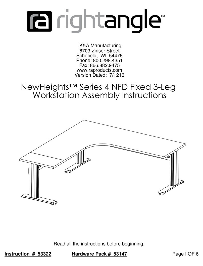
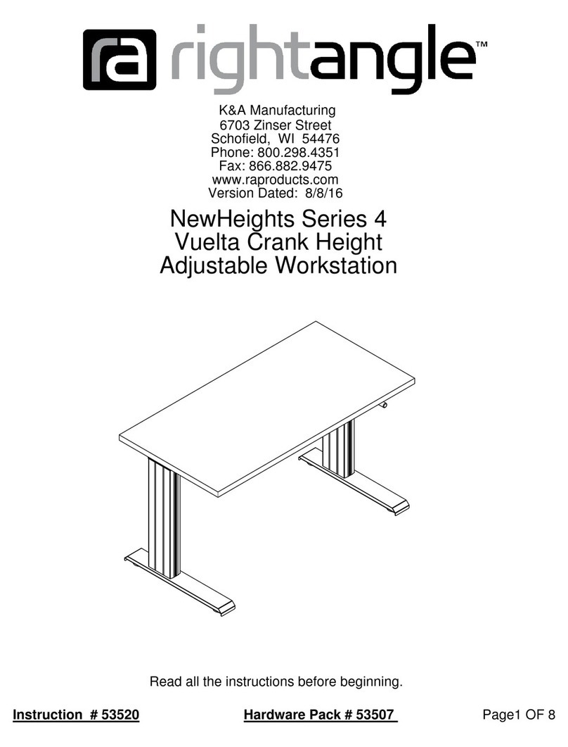
RIGHT ANGLE NewHeights 4 NZP Series User manual

Page1 OF 9Instruction # 53244 Hardware Pack # 53243
K&A Manufacturing
6703 Zinser Street
Schofield, WI 54476
Phone: 800.298.4351
Fax: 866.882.9475
www.raproducts.com
Version Dated: 7/11/16
Read all the instructions before beginning.
NewHeights™ Series 4 NZP
Levante Crank Height
Adjustable Workstation
Page 2 OF 9
K&A Manufacturing
6703 Zinser Street Schofield, WI 54476
Phone: 800.298.4351
Fax: 866.882.9475
www.raproducts.com
Tools Required for Assembly:
Power Driver W/Adjustable Torque
#2 Phillips Head Driver Bit
#2 Square Head Driver Bit
3/16" Hex Head Driver Bit or
Allen Wrench
Tape Measure
Level
Hardware Pack 53243 Drawn Actual Size
Instruction # 53244
ITEM # PART # DESCRIPTION QTY.
1 Varies NewHeights Leva te Worksurface 2
2 Varies Leva te Left Leg Assembly A 1
3 Varies Leva te Right Leg Assembly B 1
4 801347 S 4 Cra k Bracket Assembly 1
5 51708 M5 x 18mm (7/8") Sq/Ph/Wshr Head Wood Screw Varies
6 801235 Tube Leg To Diff. Drive Tube 2.04" 1
7 801247 Series 4 Leva te Deflectio Gear/Brake/Bracket Assembly 1
8 53013 Split Lock Washer 1/4" 2
9 53055 Socket Head Cap Screw 1/4-20 x 7/16 2
10 53126 Series 4 Cra k Ha dle 1
11 53141 S 4 Cra k Ha dle Clamp 1
12 Varies Series 4 Leva te Extruded I ter al Tooth Profiled Tube 1
13 53638 5/16-18 x 3/8 Butto Head Socket Screw 4
14 Not Used
15 Varies Series 4 Cross Support 1
16 800934 Cross Support E d Cap 2
17 Varies LT U-Cha el 1
51708 53013 53055 53638
52678
13
6
B
16
9
D
58
c
801235
1/2 Size 800934
1/2 Size 52336
The holes for the
tube drives must
face the inside of
the table
3
The holes for the
tube drives must
face the inside of
the table
2
Page 3 OF 9
K&A Manufacturing
6703 Zinser Street Schofield, WI 54476
Phone: 800.298.4351
Fax: 866.882.9475
www.raproducts.com
Instruction # 53244
The drawing below shows how to distinguish the left leg A from the right leg B.
Leg A Left Leg Leg B Right Leg
WARNING! Cylinders inside the leg assemblies are under pressure
Stand clear of the leg assemblies when removing the screws in Step 11.
Read the instructions thoroughly and complete the assembly before
removing the screws.
Warranty Information: NewHeights™ products are warranted to be free of defects due
to manufacturing or materials as follows: Two years on the gears. Five years on the
support brackets, aluminum columns, and feet. We will replace any defective part after
inspection by an authorized agent. Costs incurred due to product replacement such as
installation labor and transportation are not covered under this warranty. When
corresponding with RightAngle™ products, provide the model and serial numbers
located on one of the leg assemblies.
Page 4 OF 9
K&A Manufacturing
6703 Zinser Street Schofield, WI 54476
Phone: 800.298.4351
Fax: 866.882.9475
www.raproducts.com
Instruction # 53244
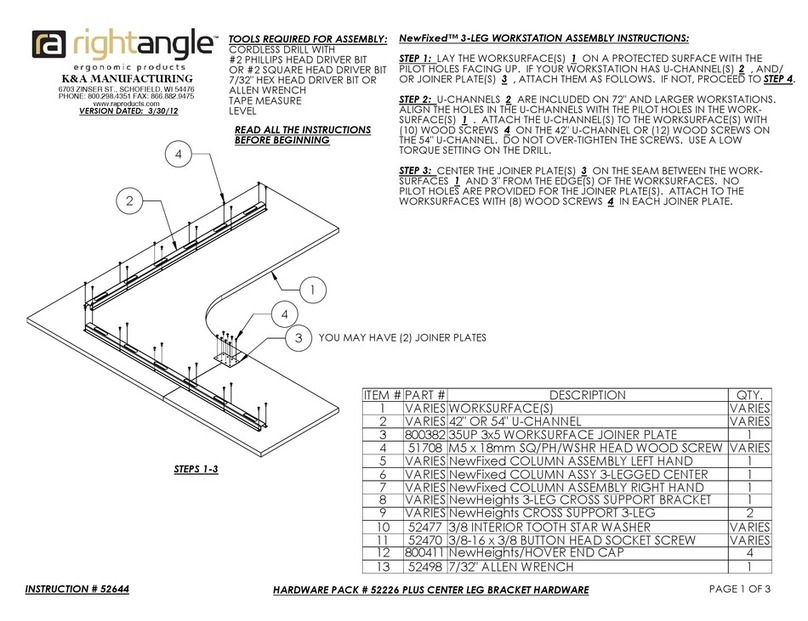
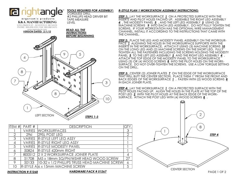
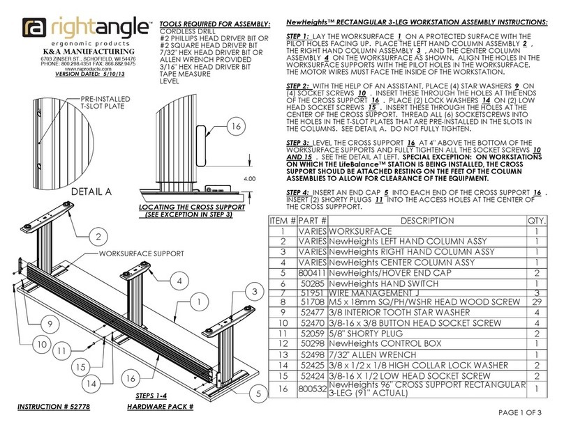
Step 1: Lay the worksurface 1on a protected surface
with the pilot holes facing up. Place the right leg
assembly 3on the worksurface aligning the holes in
the worksurface support with the pilot holes in the
worksurface. Attach the leg assembly to the work-
surface with (4) wood screws 5in the outside corners
of the worksurface support. Leave the screws loose by
about 1/8" until the cross support 15 is installed later.
Step 2: Insert the short drive tube 6into the gear
drive near the top of the right leg assembly 3. See
Detail A. Place the gear assembly 7onto the other
end of the short drive tube. Place (2) lock washers 8
on (2) cap screws 9. Insert these through the holes
in the gear assembly and thread them into the cage
nuts pre-installed in the worksurface support. See
Detail A. Hand tighten.
7
9
8
5
3
6
Worksurface
Support
Steps 1 & 2
1
A
Detail A
Cage Nuts
Gear Drive
10
4
11
1/8"-1/4"
3.706
3
10
4
11
5
C
Page 5 OF 9
K&A Manufacturing
6703 Zinser Street Schofield, WI 54476
Phone: 800.298.4351
Fax: 866.882.9475
www.raproducts.com
Instruction # 53244
Detail B
Step 3: Slide the clamp 11 onto the hex rod protruding
from the deflection gear 7. Slide the bracket
assembly 4onto the hex rod aligning the holes in the
bracket with the pilot holes in the worksurface 1.
Attach it with (4) wood screws 5. Fully tighten.
Attach the two tabs on the differential bracket
assembly 7to the worksurface with (2) wood screws 5.
Fully tighten.
Step 4: Insert the crank handle 10 through the
bracket 4and onto the hex rod. Set the crank handle
1/8" to 1/4" from the front edge of the worksurface 1.
See Detail B. Slide the clamp 11 against the back of
the bracket and tighten the screw.
Step 3
Step 4
Detail C
5
7
3
1
12
2
5
Step 5
7
Page 6 OF 9
K&A Manufacturing
6703 Zinser Street Schofield, WI 54476
Phone: 800.298.4351
Fax: 866.882.9475
www.raproducts.com
Instruction # 53244
Step 5: Slide one end of the main drive tube 12
onto the gear drive on the deflection gear 7. Place
the left leg assembly 2on the worksurface 1guiding
the other end of the drive tube into the gear drive
near the top of the left leg assembly. Align the holes
in the worksurface support with the pilot holes in the
worksurface. Attach the leg assembly to the work-
surface with (4) wood screws 5in the outside corners
of the worksurface support. Leave the screws loose
by about 1/8" as you did with the right leg assembly.
16
Step 7
15
13
Page 7 OF 9
Instruction # 53244
Step 6: With the help of an assistant align the
cross support 15 with the stickers on both leg
assemblies. See below. Insert (4) socket
screws 13 through the holes in the ends of the
cross support and thread them into the weld
nuts that are held in place by the stickers. Do not
fully tighten. Check that the cross support is level
and parallel to the worksurface. Fully tighten the
socket screws.
Step 7; Insert (2) end caps 16 into the ends of
the cross support.
Both legs
Step 6
Page 8 OF 9
K&A Manufacturing
6703 Zinser Street Schofield, WI 54476
Phone: 800.298.4351
Fax: 866.882.9475
www.raproducts.com
Instruction # 53244
Step 8: Fully tighten the (8) screws 5holding the
leg assemblies 2& 3to the worksurface 1. Drive
(8) more wood screws through the worksurface
support and into the worksurface. Fully tighten.
Step 9: Align the holes in the u-channel 17 with
the pilot holes in the worksurface 1. Attach it with
(6) to (12) wood screws 5. Fully tighten.
Step 10: Carefully remove the black socket screw
from each leg assembly 2& 3. See Detail F. Stand
aside in case the components are not properly
assembled and attached. This releases the gas
assist components inside the leg assemblies. At this
point, fully tighten the cap screws 9holding the gear
drive assembly 7to the right leg assembly 3. With
the help of an assistant, set the workstation upright
in its final location. Level the workstation if required
by turning the leveling glides clockwise (from the top)
on the low corners of the unit. If your workstation
has casters, level it by turning the bolts at the top of
the casters.
Black
Socket
Screw
Detail F
WARNING ! Cylinders inside the
leg assemblies are under pressure.
Stand clear of the leg assemblies
when removing the black socket
screws in Step 11. Read the
instructions thoroughly and
complete the assembly before
removing the screws.
Steps 8-10
5
17
5
Leveling Glide
F
A
B
C
D
E
Your worksurface may
be different than the
one shown here.
Side View
(Track wil be at
an angle when
installation is finished.)
EA
ITEM # PART # DESCRIPTION QTY.
A Varies Track Assembly 1
B 52336 3/16" Alumi um Rivet Washer .198 x .510 x .067 2
C 52678 8-18X1/2 Phillips Pa Self Drill Screw 2
D 51708 M5 x 18mm (7/8") Sq/Ph/Wshr Head Wood Screw 2
E Varies LT U-cha el 1
Page 9 OF 9
K&A Manufacturing
6703 Zinser Street Schofield, WI 54476
Phone: 800.298.4351
Fax: 866.882.9475
www.raproducts.com
Instructions To Install a Track on a Series 4
Workstation:
Step 1: Place the front of the track Aagainst the
bottom of the worksurface and the back of the track
on the angled part of the u-channel.
Instruction # 53244
Step 2: Align the holes in the track Awith one set of pilot holes in the u-channel E
keeping the front of the track 1/8"-5/8" from the front of the worksurface. Place (2) washers
Bon (2) self drilling screws C. Drive them through the track and into the u-channel.
Step 3: Attach the front of the track Ato the worksurface using (2) wood screws D. Do
not over-tighten the wood screws. Use a low torque setting on the power driver.
Step 4: Complete the installation using the instructions that came with the product you
are installing.

Other manuals for NewHeights 4 NZP Series

1

Other RIGHT ANGLE Desktop manuals

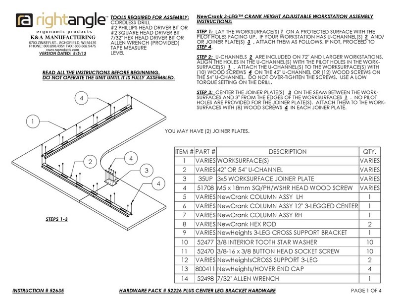
RIGHT ANGLE NewCrank 3-LEG CRANK HEIGHT ADJUSTABLE... User manual

RIGHT ANGLE

RIGHT ANGLE NewCrank 3-LEG CRANK HEIGHT ADJUSTABLE... User manual

RIGHT ANGLE NewHeights Elegante XT Series User manual

RIGHT ANGLE

RIGHT ANGLE NewHeights Elegante XT Series User manual

RIGHT ANGLE NewCrank SPLIT WORKSURFACE CRANK HEIGHT ADJUSTABLE... User manual

RIGHT ANGLE

RIGHT ANGLE NewCrank SPLIT WORKSURFACE CRANK HEIGHT ADJUSTABLE... User manual

RIGHT ANGLE NewHeights SPLIT WORKSURFACE ELECTRIC HEIGHT ADJUSTABLE... User manual

RIGHT ANGLE

RIGHT ANGLE NewHeights SPLIT WORKSURFACE ELECTRIC HEIGHT ADJUSTABLE... User manual

RIGHT ANGLE NewHeights Series User manual

RIGHT ANGLE

RIGHT ANGLE NewHeights Series User manual

RIGHT ANGLE R-STYLE PLAN 1 WORKSTATION User manual

RIGHT ANGLE

RIGHT ANGLE R-STYLE PLAN 1 WORKSTATION User manual

RIGHT ANGLE NewHeights 4 Series User manual

RIGHT ANGLE

RIGHT ANGLE NewHeights 4 Series User manual

RIGHT ANGLE NewHeights 4 NFD Series User manual

RIGHT ANGLE

RIGHT ANGLE NewHeights 4 NFD Series User manual

RIGHT ANGLE NewHeights 4 FD Series User manual

RIGHT ANGLE

RIGHT ANGLE NewHeights 4 FD Series User manual

RIGHT ANGLE NewHeights ELECTRIC HEIGHT ADJUSTABLE... User manual

RIGHT ANGLE

RIGHT ANGLE NewHeights ELECTRIC HEIGHT ADJUSTABLE... User manual

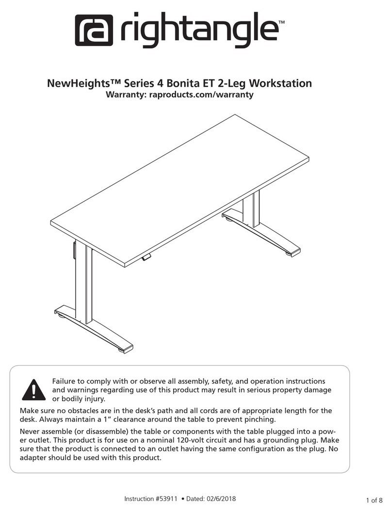
RIGHT ANGLE NewFixed 3-LEG WORKSTATION User manual
RIGHT ANGLE

RIGHT ANGLE NewFixed 3-LEG WORKSTATION User manual

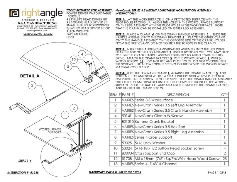
RIGHT ANGLE NewCrank 3.5 Series User manual

RIGHT ANGLE

RIGHT ANGLE NewCrank 3.5 Series User manual

RIGHT ANGLE NewHeights RECTANGULAR 3-LEG WORKSTATION User manual

RIGHT ANGLE

RIGHT ANGLE NewHeights RECTANGULAR 3-LEG WORKSTATION User manual

RIGHT ANGLE NewHeights Series User manual
RIGHT ANGLE

RIGHT ANGLE NewHeights Series User manual

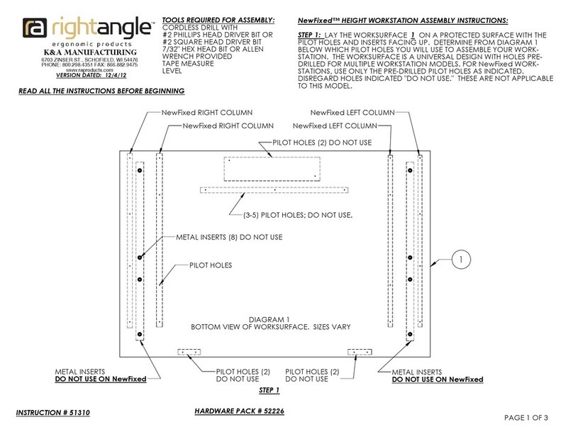
RIGHT ANGLE NewHeights 4 Bonita ET User manual

RIGHT ANGLE

RIGHT ANGLE NewHeights 4 Bonita ET User manual

RIGHT ANGLE R-STYLE PLAN 110 User manual

RIGHT ANGLE

RIGHT ANGLE R-STYLE PLAN 110 User manual

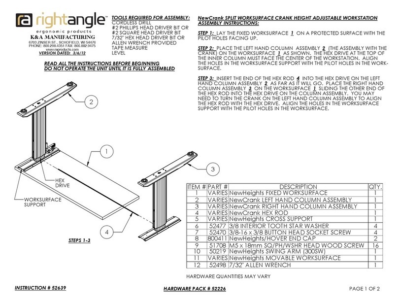
RIGHT ANGLE NewFixed HEIGHT WORKSTATION User manual
RIGHT ANGLE

RIGHT ANGLE NewFixed HEIGHT WORKSTATION User manual

Popular Desktop manuals by other brands

Acer Predator Orion 5000 user guide

Acer

Acer Predator Orion 5000 user guide

Asus T3-PH1 installation manual

Asus

Asus T3-PH1 installation manual

Acer Veriton 5100 Service guide

Acer

Acer Veriton 5100 Service guide

Lenovo ThinkCentre Edge 91 Handboek voor de gebruiker

Lenovo

Lenovo ThinkCentre Edge 91 Handboek voor de gebruiker

Fujitsu ESPRIMO P5010P VFY operating manual

Fujitsu

Fujitsu ESPRIMO P5010P VFY operating manual

Noctua NH-U12P SE1366 installation guide

Noctua

Noctua NH-U12P SE1366 installation guide

Shuttle XPC SG41J1 PLUS user guide

Shuttle

Shuttle XPC SG41J1 PLUS user guide

OCEE DESIGN DEN.Cube Assembly instructions

OCEE DESIGN

OCEE DESIGN DEN.Cube Assembly instructions

Panasonic UT-MA6 series operating instructions

Panasonic

Panasonic UT-MA6 series operating instructions

Panasonic CF-M34 Series Reference manual

Panasonic

Panasonic CF-M34 Series Reference manual

CAGSAN MERDIVEN TeleSafe S008 Instructions & user's manual

CAGSAN MERDIVEN

CAGSAN MERDIVEN TeleSafe S008 Instructions & user's manual

HP Compaq d338 MT Hardware reference guide

HP

HP Compaq d338 MT Hardware reference guide

Intel NUC 8 Enthusiast user guide

Intel

Intel NUC 8 Enthusiast user guide

Inspur NF5288M5 user manual

Inspur

Inspur NF5288M5 user manual

HP Rp3000 - Point of Sale System Hardware reference guide

HP

HP Rp3000 - Point of Sale System Hardware reference guide

Lenovo ThinkCentre M79 Hardware Maintenance Manual

Lenovo

Lenovo ThinkCentre M79 Hardware Maintenance Manual

Lenovo ThinkCentre M55 user guide

Lenovo

Lenovo ThinkCentre M55 user guide

Electronic M101H operating instructions

Electronic

Electronic M101H operating instructions

manuals.online logo
manuals.online logoBrands
  • About & Mission
  • Contact us
  • Privacy Policy
  • Terms and Conditions

Copyright 2025 Manuals.Online. All Rights Reserved.