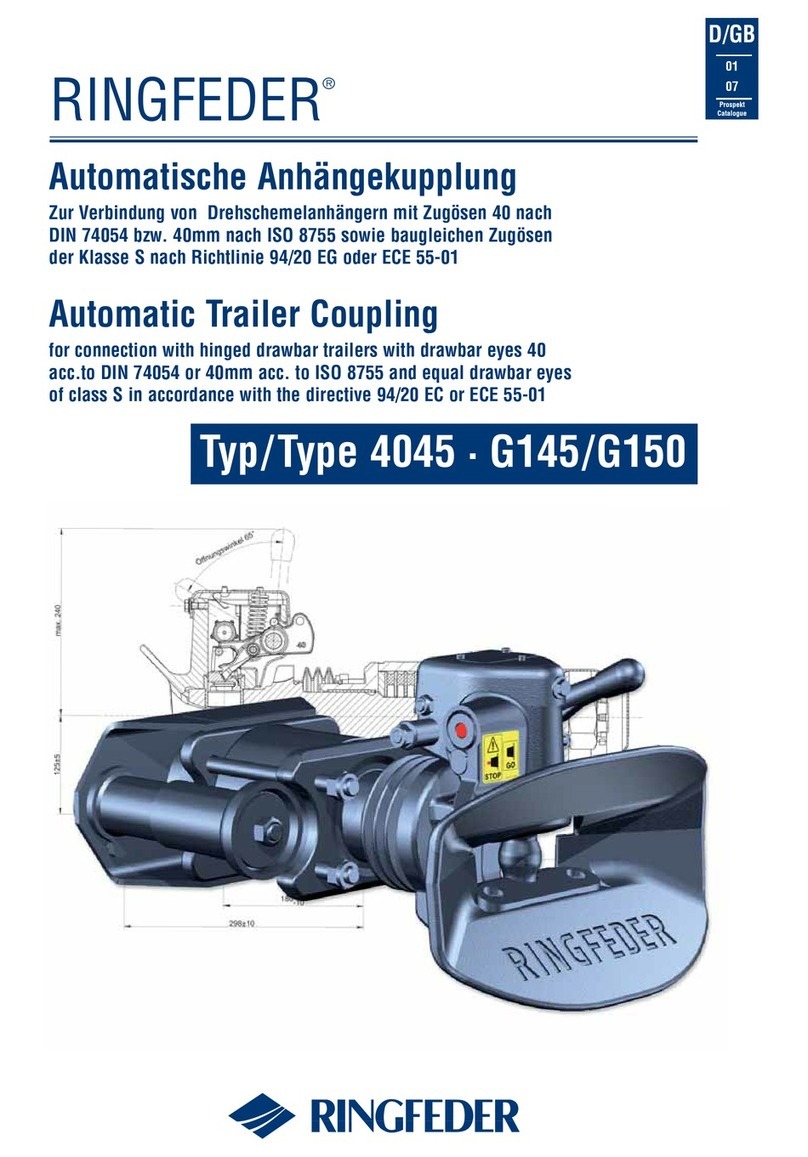
RINGFEDER 5055 User manual

Automatische Anhängekupplung
auch mit Fernbetätigung und Fernanzeige für schwere Zentralachsanhänger
mit Zugösen 50 EWG typgenehmigt nach Klasse C 50-X gemäß Richtlinie 94/20 EG
Automatic Trailer Coupling
also with distance control and remote indicator for heavy duty centre axle trailers
using 50 mm drawbar eyes EC type approval according to class C 50-X in compliance
with EC regulation 94/20
D/GB
08
06
Prospekt
Catalogue
RINGFEDER®
Typ/Type 5055

Technische Daten Technical data
Ersatzteile Spare parts
Typ 5055 Ausführung A · Type 5055 design A
Pos. No. Bezeichnung Designation
2 14 995 463 obere Führungsbuchse Top guide bush
3 14 991 247 Kuppelkörper Coupling body
4 14 994 478 Sicherung Safety device
6 14 991 239 untere Führungsbuchse Bottom guide bush
7 14 991 255 Verschleißplatte Guss Wearing plate (cast iron)
11 14 991 263 Kuppelmechanismus Ausf. A - ohne Sensor
Coupling mechanism design A - without sensor
14 14 994 529 Rückstellfeder Return spring
15 14 991 391 Hand-/Sperrhebel Kombination Ausf. A
Hand-/locking lever combination design A
15 a 14 991 312 Handhebel Ausf. A Hand lever design A
18 7 998 341 Federschwinge Spring arm
23 14 991 279 Kuppelbolzen Coupling bolt
25 14 991 273 Schließfeder Locking spring
26 14 991 367 Abschlussdeckel End cap
32 14 991 359 Sechskantschraube M10 x 115, 10.9
Hexagon screw M10 x 115, 10.9
Pos. No. Bezeichnung Designation
35 14 991 287 Plastikkappen für Mechanismus
Plastic covers for mechanism
36 13 997 942 Gummifeder Rubber spring
37 13 997 632 Druckscheibe Thrust washer
38 14 994 916 Stangenführung Bar guide
39 14 994 876 Lagerbuchse Bearing bush
40 7 995 555 Zugscheibe Tension washer
42 6 997 732 Kronenmutter M45 x 3 Castellated nut M45 x 3
43 12 991 533 Splint 8 x 80 Cotter pin 8 X 80
44 10 991 323 Schutzkappe Protecting cap
48 9 122 900 Stopfen für Sensorbohrung (10er Pack)
Plugg for sensor hole (10 pieces)
52 14 991 383 Welle mit Sperrhebel Axle with locking lever
80 14 991 406 Sensor mit Keil Sensor
14 991 341 Aufrüstsatz für Ausf. AP
Conversion kit for model AP
14 991 237 Reparatursatz Repair kit
(Pos. 2 + 6 + 7 + 23 + 43)
Typ / Type 5055 A Typ / Type 5055 A
Reparatursatz
Repair kit
2
6
7
36
3
4
11
14
15
15 a
18
25
23
26 32
35
43
37 38
39
40
42
44
48
52
80
A - C 50-X e11 00-5997 200 135 75/63 1000/2000 50 14 991 058
A + C 50-X e11 00-5997 200 135 75/63 1000/2000 50 14 991 234
ohne-/mit+ Sensor Klasse EG-Typgenehmigung D-Wert Dc-Wert V-Wert Zul. statische Stützlast Gewicht Bestellnummer
without-/with+ sensor Class EEC type approval D-Value Dc-Value V-Value Admiss. supporting load Weight Order number
94/20 EG kN kN kN kg kg

Bedienung:
Typ 5055 ohne Fernbetätigung , Ausführung A
Die Anhängekupplung ist geschlossen und gesichert, bzw. gekuppelt, d.h: die
Zugöse ist eingefahren, der Kuppelbolzen unten, die Sicherung eingerastet,
der Anzeigestift liegt in Geschlossenstellung der Sicherung bündig am
Sicherungsdeckel des Kuppelmechanismus an.
Entsichern und Öffnen der Anhängekupplung:
Zum Öffnen wird der Handhebel bis zur oberen Endstellung betätigt und
anschließend losgelassen. Hierdurch ist der Kuppelbolzen angehoben und die
Zugöse kann ausgefahren werden. Durch das Ausfahren der Zugöse wird der
Kuppelmechanismus erneut ausgelöst und die Kupplung ist wieder geschlos-
sen und gesichert.
Öffnen der Anhängekupplung zum Kuppeln der Zugöse:
Das Öffnen der Kupplung geschieht wie oben beschrieben. Der Handhebel
befindet sich in seiner oberen Endstellung, die Kupplung ist kuppelbereit.
Durch Einfahren der Zugöse in die Anhängekupplung wird der Kuppelbolzen
angehoben und dadurch der Kuppelmechanismus ausgelöst. Die Kupplung
schließt automatisch, was bedeutet, daß der Kuppelbolzen durch die
Zugösenbuchse in seine untere Stellung in die untere Führungsbuchse einge-
fahren ist. Nach jedem Kuppelvorgang ist die Geschlossenstellung der
Sicherung zu überprüfen. Sollte der Anzeigestift nicht bündig am
Sicherungsdeckel anliegen, ist die Anhängekupplung nicht gesichert und der
Kuppelvorgang muss wiederholt werden. Die Anhängekupplung Typ 5055
kann auch mit einer Fernanzeige ausgerüstet sein. Hierbei wird über einen
Sensor an der Sicherung, der mit der grünen Kontrolleuchte im Führerhaus
verbunden ist, dem Fahrer am Aufleuchen dieser grünen Kontrolleuchte
angezeigt, daß die Anhängekupplung geschlossen und gesichert ist. Sollte
diese grüne Kontrollleuchte für die Anhängekupplung nicht aufleuchten, ist
der Kuppelvorgang zu wiederholen. Dies ist nach jedem Kuppelvorgang zu
überprüfen!
Operation:
Type 5055 without distance control, Model A
The trailer coupling is closed and secured, resp. coupled, that is to say the
towing eye is inserted, the coupling bolt in its lower position, the safety devi-
ce is engaged, the indicator pin in this secured position of the safety device
is fitting flush to the safety cap in the coupling mechanism.
Releasing and opening of the trailer coupling:
To open the coupling the handle is moved to its upper end position and then
released. This will cause the coupling bolt to lift up and the towing eye may
be extended. Due to the extension of the towing eye the coupling mechanism
is again released and thus, the coupling repeatedly closed and secured.
Opening of the trailer coupling and engaging the towing eye:
To open the trailer coupling proceed as described above. The coupling lever
is in its upper end position, the coupling is set ready for its next engagement.
When inserting the towing eye, the coupling mechanism is released by lifting
the coupling bolt. The coupling closes automatically, which means that the
coupling bolt is inserted through the towing eye bush in its lower position in
the bottom guide bush.
Check that after each coupling process the safety device is fully engaged. If
the indicator pin is not fitting closely to the safety cap the trailer coupling is
unsecured and the whole procedure must be repeated.
The trailer coupling type 5055 may also be equipped with a remote indicator.
In such a case a sensor on the safety device which is connected with the
green indicator lamp in the cab indicates to the driver by lighting up that the
trailer coupling is closed and secured. If this green indicator lamp does not
light up the whole procedure must be repeated. Check after each coupling
process!
~ 67º
104 ±5 226 ±5
35 30
175 210
310
max. 285
max. ø 94
ø 21
100
211+9
-0
360+20
140
160
200

Technische Daten Technical data
Ersatzteile Spare parts
Pos. No. Bezeichnung Designation
2 14 995 463 obere Führungsbuchse Top guide bush
3 14 991 247 Kuppelkörper Coupling bodye
4 14 994 478 Sicherung Safety device
6 14 991 239 untere Führungsbuchse Bottom guide bushr
7 14 991 255 Verschleißplatte Guss Wearing plate (cast iron)
11 14 991 315 Kuppelmechanismus Handhebel links kompl.
ohne Sensor Coupling mechanism hand lever left
cpl. without sensor
14 14 994 529 Rückstellfeder Return spring
15 14 991 253 Hand-/Sperrhebel Kombination Ausf. AW, AP
Hand-/locking lever combination design AW, AP
15 c 14 991 236 Handhebel Ausf. AW, AP, links Hand lever design
AW, AP, left
18 7 998 341 Federschwinge Spring arm
23 14 991 279 Kuppelbolzen Coupling bolt
25 14 991 273 Schließfeder Locking spring
26 14 991 367 Abschlussdeckel End cap
32 14 991 359 Sechskantschraube M10 x 115, 10.9
Hexagon screw M10 x 115, 10.9
35 14 991 287 Plastikkappen für Mechanismus
Plastic covers for mechanism
36 13 997 942 Gummifeder Rubber spring
Pos. No. Bezeichnung Designation
37 13 997 632 Druckscheibe Thrust washer
38 14 994 916 Stangenführung Bar guide
39 14 994 876 Lagerbuchse Bearing bush
40 7 995 555 Zugscheibe Tension washer
42 6 997 732 Kronenmutter M45 x 3 Castellated nut M45 x 3
43 12 991 533 Splint 8 x 80 Cotter pin 8 X 80
44 10 991 323 Schutzkappe Protecting cap
48 9 122 900 Stopfen für Sensorbohrung (10er Pack)
Plugg for sensor hole (10 pieces)
52 c 14 991 261 Welle mit Sperrhebel Axle with locking lever
70 14 991 326 Seilzug mit Federspeicher, Anbausatz
Cable pull with spring accumulator, compl. kit
70 a 14 999 697 Seilzug Cable pull
70 b 14 994 505 Gasfeder Gas spring
70 c 14 991 294 Gegenlagersatz Bracket kit
70 e 14 994 492 Hebelsatz kompl. Lever kit
70 h 14 991 319 Adaptersatz Adapter kit
80 14 991 406 Sensor mit Keil Sensor
14 991 237 Reparatursatz Repair kit
(Pos. 2 + 6 + 7 + 23 + 43)
Typ / Type 5055 AW Typ / Type 5055 AW
Reparatursatz
Repair kit
2
6
7
36
3
4
11
14
70 a
18
25
23
26 32
35
43
37
40
42
44
70
52 c 70 b
70 h
80
15 c
48
38
39
70 c
70 e
15
AW C 50-X e11 00-5997 200 135 75/63 1000/2000 57 14 991 059
Ausführung Klasse EG-Typgenehmigung D-Wert Dc-Wert V-Wert Zul. statische Stützlast Gewicht Bestellnummer
Design Class EEC type approval D-Value Dc-Value V-Value Admiss. supporting load Weight Order number
94/20 EG kN kN kN kg kg
mit Fernbetätigung und Fernanzeige
including distance control and remote indicator
Typ 5055 Ausführung AW · Type 5055 design AW

BB
Bedienung:
Typ 5055 Ausführung AW mit Fernbetätigung über Bowdenzug mit Feder-
speicher und mit Fernanzeige
Öffnen der Anhängekupplung:
Betätigungshebel durch Öffnen des Schlosses entriegeln. Betätigungshebel
am Betätigungsgerät drehen bis der Hebel über das Gelenk in “Totlage” liegt.
Dadurch ist der Hebel arretiert. Wenn der Kuppelbolzen nicht durch die Zug-
öse verspannt war, wird er durch das Umlegen des Hebels hochgezogen und
die Anhängekupplung ist geöffnet. Nun kann die Zugöse ausgefahren werden.
Anschließend ist der Hebel wieder aus seiner “Totlage” zu lösen und durch
Umlegen in seine “Nullage” zu bringen und durch Abschließen zu sichern.
Öffnet die Kupplung nach Drehen des Hebels in seine “Totlage” nicht, so ist
der Kuppelbolzen durch die Zugöse verspannt. In diesem Fall kann der Fahrer
durch leichtes Rucken mit dem Zugfahrzeug versuchen, den Kuppelbolzen
frei zu bekommen. Über den im Betätigungsgerät eingebauten Federspeicher
wird der Kuppelbolzen weiterhin mit einer Zugkraft beaufschlagt, die ihn,
sobald er frei wird, nach oben zieht und so die Kupplung öffnet und die Zug-
öse ausgefahren werden kann. Nach erfolgtem Abkuppeln ist der Hebel wie-
der aus seiner “Totlage” zu lösen und durch Umlegen in seine “Nullage” zu
bringen und durch Abschließen zu sichern.
Öffnen der Anhängekupplung und Kuppeln der Zugöse:
Die Anhängekupplung wird wie oben beschrieben geöffnet. Wenn der
Kuppelbolzen oben eingerastet ist, wird der Betätigungshebel wieder umge-
legt in seine Nullage. Die Anhängekupplung ist nun kuppelbereit und die
Zugöse kann eingefahren werden. Durch das Einfahren der Zugöse wird der
Kuppelbolzen angehoben und der Kuppelmechanismus ausgelöst. Nach dem
Ankuppeln muss der Fahrer am Aufleuchten der grünen Kontrolleuchte für
die Anhängekupplung im Führerhaus oder an der Stellung des Anzeigestiftes
kontrollieren, ob die Kupplung geschlossen und gesichert ist. Sollte dies
nicht der Fall sein, ist der Kuppelvorgang zu wiederholen. Anschließend ist
der Betätigungshebel unbedingt abzuschließen, um ihn gegen unbeabsichtig-
tes Öffnen (auch während der Fahrt) zu sichern.
Operation:
Type 5055 Model AW including distance control via Bowden cable with
spring accumulator and remote indicator
Opening of the trailer coupling:
Release opening lever by unlocking the padlock. Turn operating lever on the
operating mechanism until the lever over the joint is situated in its dead-cen-
ter position. By this the lever is locked. If the coupling bolt was not jammed
with the towing eye it is lifted up by moving the lever, and thus, the trailer
coupling opens. Now the towing eye can be extended. Upon that the lever has
to be released from its dead-center position and be moved to its “zero” posi-
tion. Secure by locking it up.
If the coupling does not open after turning the lever in its dead-center positi-
on, the coupling bolt is jammed with the towing eye. In such a case the driver
can try to release the coupling bolt by slightly jerking on the towing vehicle.
By the spring accumulator incorporated in the operating mechanism the coup-
ling bolt is further admitted with a tensile force allowing it, once being
released, to lift and thus the coupling to open so that the towing eye can be
extended. After disengaging, the lever has to be released again from its dead-
center position and be moved in its “zero” position. Attend to locking it up
again.
Opening of the coupling and engaging the towing eye:
The trailer coupling is opened as described above. When the coupling bolt is
engaged in its upper end position the operating lever is again moved in its
“zero” position. The trailer coupling is now ready for engagement and the
towing eye can be inserted. By inserting the towing eye the coupling mecha-
nism is released by lifting the coupling bolt. After engaging the coupling the
driver has to check by lighting up of the green indicator lamp for the trailer
coupling in the cab or by the position of the indicator pin whether the coup-
ling is closed and secured. If this is not the case the whole procedure must
be repeated. Upon that attend to locking up the operating lever to protect
against unintended opening (also during driving). In case of failure of the
Bowden cable the coupling can be opened by means of a pertaining emer-
gency opening lever which always has to be available in the tool kit, by put-
ting it against the hexagon shaft.
ø 21
100
140
160
200

Technische Daten Technical data
Ersatzteile Spare parts
Typ 5055 Ausführung AP · Type 5055 design AP
Pos. No. Bezeichnung Designation
2 14 995 463 obere Führungsbuchse Top guide bush
3 14 991 247 Kuppelkörper Coupling body
4 14 994 478 Sicherung Safety device
6 14 991 239 untere Führungsbuchse Bottom guide bush
7 14 991 255 Verschleißplatte Guss Wearing plate (cast iron)
11 14 991 315 Kuppelmechanismus Handhebel links kompl.
ohne Sensor Coupling mechanism hand lever left
cpl. without sensor
14 14 994 529 Rückstellfeder Return spring
15 14 991 253 Hand-/Sperrhebel Kombination Ausf. AW, AP
Hand-/locking lever combination design AW, AP
15 c 14 991 236 Handhebel, Ausf AW, AP, links Hand lever design
AW, AP, left
18 7 998 341 Federschwinge Spring arm
23 14 991 279 Kuppelbolzen Coupling bolt
25 14 991 273 Schließfeder Locking spring
26 14 991 367 Abschlussdeckel End cap l
32 14 991 359 Sechskantschraube M10 x 115, 10.9
Hexagon screw M10 x 115, 10.9
35 14 991 287 Plastikkappen für Mechanismus
Plastic covers for mechanism
Pos. No. Bezeichnung Designation
36 13 997 942 Gummifeder Rubber spring
37 13 997 632 Druckscheibe Thrust washer
38 14 994 916 Stangenführung Bar guide
39 14 994 876 Lagerbuchse Bearing bush
40 7 995 555 Zugscheibe Tension washer
42 6 997 732 Kronenmutter M45 x 3 Castellated nut M45 x 3
43 12 991 533 Splint 8 x 80 Cotter pin 8 X 80
44 10 991 323 Schutzkappe Protecting cap
48 9 122 900 Stopfen für Sensorbohrung (10er Pack)
Plugg for sensor hole (10 pieces)
52 c 14 991 261 Welle mit Sperrhebel Axle with locking lever
53 14 996 031 Ventilkasten kompl. Valve box cpl.
53 a 14 996 047 Ventilkasten ohne Ventile Valve box without velves
80 14 991 406 Sensor mit Keil Sensor
81 14 994 516 Power Actuator Power Actuator
82 14 994 474 Luftanschlussteile für Power Actuator
Air nipples für Power Actuator
84 14 991 292 Konsolsatz Bracket kit
92 14 991 316 Adaptersatz Adapter kit
14 991 237 Reparatursatz Repair kit
(Pos. 2 + 6 + 7 + 23 + 43)
Typ / Type 5055 AP Typ / Type 5055 AP
Reparatursatz
Repair kit
2
6
7
36
3
4
11
14
18
25
23
26 32
35
43
37
40
42
44
80
92
84
38
39
82
81
48
52 c
15 c
15
AP C 50-X e11 00-5997 200 135 75/63 1000/2000 60 14 991 081
Ausführung Klasse EG-Typgenehmigung D-Wert Dc-Wert V-Wert Zul. statische Stützlast Gewicht Bestellnummer
Design Class EEC type approval D-Value Dc-Value V-Value Admiss. supporting load Weight Order number
94/20 EG kN kN kN kg kg
mit Fernbetätigung und Fernanzeige
including distance control and remote indicator

Operation:
Type 5055 Model AP including distance control via power actuator and
remote indicator
The trailer coupling is closed and secured, resp. coupled that is to say the
towing eye is inserted, the coupling bolt in its lower position, the safety device
is engaged, the indicator pin in this secured position of the safety device is fit-
ting flush to the safety cap, the green indicator lamp for the trailer coupling in
the cab lights up.
Opening of the trailer coupling and uncoupling:
Unlock and open the valve box door. Turn the red handle clockwise to “ON”
and fold out the yellow handle. Simultaneously press on the yellow handle
where it says “Press” and turn the yellow handle anti-clockwise to “OPEN”.
The mechanism is hereby admitted with compressed air and the coupling
bolt lifted up via shaft and locking lever. (In case the coupling bolt gets jam-
med with the towing eye, the driver can attend to releasing the coupling bolt
by slightly jerking on the towing vehicle and thus, causing the trailer coup-
ling to open.) Then turn the yellow handle back to “CLOSE” and fold them in.
Uncouple the trailer. The coupling closes, when the trailer is disconnected.
Turn the red handle anti-clockwise to “OFF”.Close and lock up the valve box
door.
(The valve box door can only be closed when both handles are in the closed
position.)
Opening of the trailer coupling and coupling:
Unlock and open the valve box door. Turn the red handle clockwise to “ON”
and fold out the yellow handle. Simultaneously press on the yellow handle
where it says “Press” and turn the yellow handle anti-clockwise to “OPEN”.
The mechanism is hereby admitted with compressed air and the coupling
bolt lifted up via shaft and locking lever. Then turn the yellow handle back to
“CLOSE” and fold them in. Couple to the trailer. The coupling will close when
the towing eye pushes up the coupling bolt and this releases the mechanism.
Check, that the green light in the cabin for the coupling lights up. Check, that
the indicator pin is completely in. (Indicator pin flush with the safety cap) If
the indicator pin is not completely in and the green light in the cabin for the
coupling does not light up, the coupling procedure must be repeated. Only
when the indicator pin is completely in and the green light in the cabin for the
coupling lights up the coupling is closed and secured correctly. When the
trailer is coupled correctly turn back the red handle anti-clockwise into “OFF”
then close and lock up the valve box door. (The valve box door can only be
closed when both handles are in the closed position.) Now the trailer is secu-
red and driving may begin. In case of failure of the compressed air supply the
coupling can be opened by the hand-lever.
100
140
160
200
104 ±5
max. ø 94
175 210
35 30
310
max. 272
~ 67º
211+9
-0
360+20
Bedienung:
Typ 5055 Ausführung AP mit Fernbetätigung über Power Actuator und mit
Fernanzeige
Die Anhängekupplung ist geschlossen und gesichert, bzw. gekuppelt, d.h: die
Zugöse ist eingefahren, der Kuppelbolzen unten, die Sicherung eingerastet,
der Anzeigestift liegt in Geschlossenstellung der Sicherung bündig am Siche-
rungsdeckel im Kuppelmechanismus an, die grüne Kontrollleuchte für die
Anhängekupplung im Führerhaus leuchtet auf.
Öffnen der Anhängekupplung und Entkuppeln:
Schließen Sie den Ventilkasten auf und öffnen Sie die Ventilkastentür. Drehen
Sie den roten Handhebel im Uhrzeigersinn in die Stellung “ON” und klappen
Sie den gelben Handhebel aus. Drücken Sie auf “PRESS” und drehen Sie den
gelben Handhebel in die Stellung “OPEN”. Hierdurch wird der Mechanismus
mit Druckluft beaufschlagt und der Kuppelbolzen nach oben gezogen. (Bei
eventuellem Verklemmen des Kuppelbolzens mit der Zugöse kann der Fahrer
durch leichtes Rucken mit dem Zugfahrzeug dafür sorgen, daß der
Kuppelbolzen frei wird und die Anhängekupplung öffnet.) Danach drehen Sie
den gelben Handhebel zurück in die Stellung “CLOSE” und klappen ihn wieder
ein. Entkuppeln Sie den Anhänger. Die Kupplung schließt selbsttätig, wenn
die Zugöse des Anhängers ausgefahren ist. Drehen Sie den roten Handhebel
entgegen dem Uhrzeigersinn in Stellung “OFF”. Schließen Sie die Ventil-
kastentür und schließen Sie den Ventilkasten ab.
(Die Ventilkastentür kann nur dann geschlossen werden, wenn beide Hand-
hebel in ihrer geschlossenen Stellung stehen.)
Öffnen der Anhängekupplung und Kuppeln der Zugöse:
Schließen Sie den Ventilkasten auf und öffnen Sie die Ventilkastentür. Drehen
Sie den roten Handhebel im Uhrzeigersinn in die Stellung “ON” und klappen
Sie den gelben Handhebel aus. Drücken Sie auf “PRESS” und drehen Sie den
gelben Handhebel in die Stellung “OPEN” Hierdurch wird der Mechanismus
mit Druckluft beaufschlagt und der Kuppelbolzen nach oben gezogen.
Danach drehen Sie ihn zurück in die Stellung “CLOSE” und klappen ihn wie-
der ein. Kuppeln Sie den Anhänger an. Die Kupplung schließt, wenn die
Zugöse den Kuppelbolzen angehoben hat und dadurch der Mechanismus
ausgelöst wird. Überprüfen Sie, daß die grüne Kontrolleuchte für die
Anhängekupplung im Führerhaus aufleuchtet. Überprüfen Sie, ob der
Anzeigestift bündig mit dem Sicherungsdeckel abschließt. Wenn der
Anzeigestift nicht bündig mit dem Sicherungsdeckel abschließt und die grüne
Kontrolleuchte für die Anhängekupplung im Führerhaus nicht aufleuchtet,
muss der Kuppelvorgang wiederholt werden. Nur wenn der Anzeigestift bün-
dig mit dem Sicherungs-deckel abschließt und die grüne Kontrolleuchte für
die Anhängekupplung im Führerhaus aufleuchtet ist die Kupplung vor-
schriftsmäßig geschlossen und gesichert. Wenn der Anhänger vorschrifts-
mäßig angekuppelt ist, drehen Sie den roten Handhebel entgegen dem
Uhrzeigersinn in Stellung “OFF”. Danach schließen Sie die Ventilkastentür
und schließen den Ventilkasten ab.
(Die Ventilkastentür kann nur dann geschlossen werden, wenn beide
Handhebel in ihrer geschlossenen Stellung stehen.)
Nun ist der Anhänger sicher gekuppelt und es kann losgefahren werden. Bei
Ausfall der Druckluft kann die Kupplung auch über den Handhebel geöffnet
werden.
53, 53 a
ø 21

Technische Daten Technical data
Ersatzteile Spare parts
Typ 5055 Ausführung AM · Type 5055 design AM
Pos. No. Bezeichnung Designation
2 14 995 463 obere Führungsbuchse Top guide bush
3 14 991 247 Kuppelkörper Coupling body
4 14 994 478 Sicherung Safety device
6 14 991 239 untere Führungsbuchse Bottom guide bush
7 14 991 255 Verschleißplatte Guss Wearing plate (cast iron)
11 14 991 286 Kuppelmechanismus AM kompl. ohne Sensor
Coupling mechanism AM cpl. without sensor
14 14 994 529 Rückstellfeder Return spring
15 14 991 391 Hand-/Sperrhebel Kombination Ausf. A
Hand-/locking lever combination design A
15 a 14 991 312 Handhebel Ausf. A Hand lever design A
18 7 998 341 Federschwinge Spring arm
23 14 991 279 Kuppelbolzen Coupling bolt
25 14 991 273 Schließfeder Locking spring
26 14 991 390 Abschlussdeckel AM, kompl. AM-Einheit
End cap AM, compl. AM-unit
26 d 9 122 400 Stopfen (10er Pack als ET)
Plug (10er Pack als ET)
26 i 14 991 269 Knebelkerbstift Shaft
14 991 245 Membransatz für AM-Einheit
Membrane kit for AM-unit
Pos. No. Bezeichnung Designation
32 14 991 359 Sechskantschraube M10 x 115, 10.9
Hexagon screw M10 x 115, 10.9
35 14 991 287 Plastikkappen für Mechanismus
Plastic covers for mechanism
36 13 997 942 Gummifeder Rubber spring
37 13 997 632 Druckscheibe Thrust washer
38 14 994 916 Stangenführung Bar guide
39 14 994 876 Lagerbuchse Bearing bush
40 7 995 555 Zugscheibe Tension washer
42 6 997 732 Kronenmutter M45 x 3 Castellated nut M45 x 3
43 12 991 533 Splint 8 x 80 Cotter pin 8 X 80
44 10 991 323 Schutzkappe Protecting cap
48 9 122 900 Stopfen für Sensorbohrung (10er Pack)
Plugg for sensor hole (10 pieces)
52 14 991 383 Welle mit Sperrhebel Axle with locking lever
53 14 996 031 Ventilkasten kompl. Valve box cpl.
53 a 14 996 047 Ventilkasten ohne Ventile Valve box without velves
80 14 991 406 Sensor mit Keil Sensor
14 991 237 Reparatursatz Repair kit
(Pos. 2 + 6 + 7 + 23 + 43)
Typ / Type 5055 AM Typ / Type 5055 AM
Reparatursatz
Repair kit
2
6
7
36
3
4
11
14
18
25
23
26
32
35
43
37
40
42
44
80
38
39
48
15
15 a
52
26 d
AM C 50-X e11 00-5997 200 135 75/63 1000/2000 55 14 991 060
Ausführung Klasse EG-Typgenehmigung D-Wert Dc-Wert V-Wert Zul. statische Stützlast Gewicht Bestellnummer
Design Class EEC type approval D-Value Dc-Value V-Value Admiss. supporting load Weight Order number
94/20 EG kN kN kN kg kg
mit Fernbetätigung und Fernanzeige
including distance control and remote indicator
Membransatz
Membrane kit

Bedienung:
Typ 5055 Ausführung AM mit Fernbetätigung über Air Mechanism und mit
Fernanzeige
Die Anhängekupplung ist geschlossen und gesichert, bzw. gekuppelt, d.h. die
Zugöse ist eingefahren, der Kuppelbolzen unten, die Sicherung eingerastet,
der Anzeigestift liegt in Geschlossenstellung der Sicherung bündig am Siche-
rungsdeckel im Kuppelmechanismus an, die grüne Kontrolleuchte für die
Anhängekupplung im Führerhaus leuchtet auf.
Öffnen der Anhängekupplung und Entkuppeln:
Schließen Sie den Ventilkasten auf und öffnen Sie die Ventilkastentür. Drehen
Sie den roten Handhebel im Uhrzeigersinn in die Stellung “ON“ und klappen
Sie den gelben Handhebel aus. Drücken Sie auf “PRESS” und drehen Sie den
gelben Handhebel in die Stellung “OPEN”.
Hierdurch wird der Mechanismus mit Druckluft beaufschlagt und der
Kuppelbolzen nach oben gezogen. (Bei eventuellem Verklemmen des
Kuppelbolzens mit der Zugöse kann der Fahrer durch leichtes Rucken mit
dem Zugfahrzeug dafür sorgen, daß der Kuppelbolzen frei wird und die
Anhängekupplung öffnet.) Danach drehen Sie den gelben Handhebel zurück
in die Stellung “CLOSE” und klappen ihn wieder ein.
Entkuppeln Sie den Anhänger. Die Kupplung schließt selbsttätig, wenn die
Zugöse des Anhängers ausgefahren ist. Drehen Sie den roten Handhebel ent-
gegen dem Uhrzeigersinn in Stellung “OFF”. Schließen Sie die Ventilkastentür
und schließen Sie den Ventilkasten ab.
(Die Ventilkastentür kann nur dann geschlossen werden, wenn beide
Handhebel in ihrer geschlossenen Stellung stehen.)
Öffnen der Anhängekupplung und Kuppeln der Zugöse:
Schließen Sie den Ventilkasten auf und öffnen Sie die Ventilkastentür. Drehen
Sie den roten Handhebel im Uhrzeigersinn in die Stellung “ON” und klappen
Sie den gelben Handhebel aus. Drücken Sie auf “PRESS” und drehen Sie den
gelben Handhebel in die Stellung “OPEN”.
Hierdurch wird der Mechanismus mit Druckluft beaufschlagt und der
Kuppelbolzen nach oben gezogen. Danach drehen Sie ihn zurück in die
Stellung “CLOSE” und klappen ihn wieder ein. Kuppeln Sie den Anhänger an.
Die Kupplung schließt, wenn die Zugöse den Kuppelbolzen angehoben hat
und dadurch der Mechanismus ausgelöst wird. Überprüfen Sie, daß die
grüne Kontrolleuchte für die Anhängekupplung im Führerhaus aufleuchtet.
Überprüfen Sie, ob der Anzeigestift bündig mit dem Sicherungsdeckel
abschließt. Wenn der Anzeigestift nicht bündig mit dem Sicherungsdeckel
abschließt und die grüne Kontrolleuchte für die Anhängekupplung im
Führerhaus nicht aufleuchtet, s der Kuppelvorgang wiederholt werden. Nur
wenn der Anzeigestift bündig mit dem Sicherungsdeckel abschließt und die
grüne Kontrolleuchte für die Anhängekupplung im Führerhaus aufleuchtet ist
die Kupplung vorschriftsmäßig geschlossen und gesichert. Wenn der
Anhänger vorschriftsmäßig angekuppelt ist, drehen Sie den roten Handhebel
entgegen dem Uhrzeigersinn in Stellung “OFF”. Danach schließen Sie die
Ventilkastentür und schließen den Ventilkasten ab.
(Die Ventilkastentür kann nur dann geschlossen werden, wenn beide
Handhebel in ihrer geschlossenen Stellung stehen.) Nun ist der Anhänger
sicher gekuppelt und es kann losgefahren werden. Bei Ausfall der Druckluft
kann die Kupplung auch über den Handhebel geöffnet werden.
Operation:
Type 5055 Model AM, with distance control via Air Mechanism, including
remote indicator
The trailer coupling is closed and secured, resp. coupled, that is to say the
towing eye is inserted, the coupling bolt in its lower position, the safety devi-
ce is engaged, the indicator pin in this closed position of the safety device is
fitting flush to the safety cap in the coupling mechanism, the green indicator
lamp for the trailer coupling in the cab lights up.
Opening of the trailer coupling and uncoupling:
Unlock and open the valve box door. Turn the red handle clockwise to “ON”
and fold out the yellow handle. Simultaneously press on the yellow handle
where it says “Press” and turn the yellow handle anti-clockwise to “OPEN”.
The mechanism is hereby admitted with compressed air and the coupling
bolt lifted up via shaft and locking lever. (In case the coupling bolt gets jam-
med with the towing eye, the driver can attend to releasing the coupling bolt
by slightly jerking on the towing vehicle and thus, causing the trailer coup-
ling to open.) Then turn the yellow handle back to “CLOSE” and fold them in.
Uncouple the trailer. The coupling closes, when the trailer is disconnected.
Turn the red handle anti-clockwise to “OFF”.Close and lock up the valve box
door.
(The valve box door can only be closed when both handles are in the closed
position.)
Opening of the trailer coupling and coupling:
Unlock and open the valve box door. Turn the red handle clockwise to “ON”
and fold out the yellow handle. Simultaneously press on the yellow handle
where it says “Press” and turn the yellow handle anti-clockwise to “OPEN”.
The mechanism is hereby admitted with compressed air and the coupling
bolt lifted up via shaft and locking lever. Then turn the yellow handle back to
“CLOSE” and fold them in. Couple to the trailer. The coupling will close when
the towing eye pushes up the coupling bolt and this releases the mechanism.
Check, that the green light in the cabin for the coupling lights up. Check, that
the indicator pin is completely in. (Indicator pin flush with the safety cap) If
the indicator pin is not completely in and the green light in the cabin for the
coupling does not light up, the coupling procedure must be repeated. Only
when the indicator pin is completely in and the green light in the cabin for the
coupling lights up the coupling is closed and secured correctly. When the
trailer is coupled correctly turn back the red handle anti-clockwise into “OFF”
then close and lock up the valve box door.
(The valve box door can only be closed when both handles are in the closed
position.) Now the trailer is secured and driving may begin. In case of failu-
re of the compressed air supply the coupling can be opened by the hand-
lever.
100
140
160
200
~ 67º
35 30
175 210
310
104 ±5 286 ±5
max. ø 94
53, 53 a
ø 21

Die Anhängekupplungen Typ 5055 sind bis zu
einem D-Wert von 200 kN zugelassen. Bei
Fahrzeugkombinationen bis zu einem D-Wert
von 120 kN (130 kN) dürfen diese Anhänge-
kupplungen in Verbindung mit Zugösen 50
Form A oder B nach DIN 74053 bzw. D 50-A
oder B gemäß Richtlinie 94/20 EG betrieben
werden. Darüber hinaus ist der Einsatz bis zu
einem D-Wert von 200 kN nur in Verbindung
mit einer 50 mm Schwertransportzugöse
oder mit Zugösen nach Klasse D 50 gemäß
Richtlinie 94/20 EG mit entsprechend hohem
D-Wert zulässig (z.B. Ringfeder Typ 480).
Zugöse Ringfeder Typ 480
nach Klasse D 50-X gemäß 94/20 EG
EWG-Typgenehmigung e1 00-0166
D 50-X D 260 kN
Dc135 kN
e1 S 1000 kg
00-0166 V 75 kN
Anhängekupplung Typ 5055 zur Verbindung mit Zugösen der Klasse D50
gemäß Richtlinie 94/20 EG oder nach ISO 1102 oder Zugösen 50 DIN 74053
sowie 50 mm Schwerlastzugösen (Ringfeder Best-Nr. 6 991 394 oder baugleich).
Ringfeder Zugöse Typ 480 · Bestell-Nr. 9994 939
Ringfeder drawbar eye type 480 · Order No. 9994 939
Ringfeder Schwerlastzugöse · Bestell-Nr. 6991 394
Ringfeder heavy duty drawbar eye · Order No. 6991 394
165
165
Type 5055 trailer couplings are approved up
to a D-value of 200 kN. In vehicle combinati-
ons up to a D-value of 120 kN (130 kN) these
trailer couplings may be operated in combina-
tion with 50 mm drawbar eyes, design A or B
in accordance with DIN 74053 and D 50-A or
B in compliance with EC regulation 94/20. In
addition, they may exclusively be employed
up to a D-value of 200 kN in combination with
a 50 mm heavy duty drawbar eye as shown
on the representation, or with drawbar eyes
according to class D 50 in compliance with
EC regulation 94/20 having a correspondingly
high D-value (e.g. type 480 Ringfeder).
Type 480 Ringfeder Drawbar Eye
according to class D 50-X in compliance
with EC 94/20 EEC type approval
e1 00-0166
D 50-X D 260 kN
Dc135 kN
e1 S 1000 kg
00-0166 V 75 kN
Type 5055 trailer coupling to combine with class D50 drawbar eyes in accordance with EC
regulation 94/20 or ISO 1102 or to combine with 50 mm DIN 74053 drawbar eyes and 50
mm heavy duty drawbar eyes (Ringfeder Order No. 6 991 394 or equal).

Technical Data
D-value for towing vehicle and
semi-trailer:
The calculated D-Value may be
less or equal to the D-value of the coupling
T: max. mass in tonnes of the towing vehicle
R: max. mass in tonnes of the semi-trailer
g: acceleration due to gravity 9.81 m/s2
Important Instruction: When fitting (or repla-
cing) the trailer coupling the relevant legal regu-
lations and the instructions from the car manu-
facturers have to be observed.
Dc-value for towing vehicle and centre
axle trailer:
(only applicable in connection with the V-value)
The calculated Dc-value may be less or equal to
the Dc-value of the coupling.
T: max. mass in tonnes of the towing vehicle
C: sum of the axle loads of the centre axle trailer
carrying maximum permissible load, in ton-
nes
g: acceleration due to gravity 9.81 m/s2
V-value for the centre axle trailer
(only applicable in connection with the
Dc-value)
The calculated V-value may be less or equal to
the V-value of the coupling.
a: equivalent vertical acceleration in the coup-
ling point in m/s2
a = 1.8 for vehicles with air suspension
a = 2,4 for vehicles with other suspension
l: theoretical drawbar length in metres
X: length of the loading area of the
trailer in metres
X2/l2at least 1.0 (for the calculation)
C: sum of the axle loads of the centre axletrailer
carrying maximum permissible load, in ton-
nes
EEC Type Approval: The mounting of the trailer
coupling has to be checked in accordance with
the regulations contained in appendix I, no. 5.10
and in compliance with the requirements laid
down in appendix VII of the EC regulation 94/20.
D (kN) = g · T · R
T + R Dc (kN) = g · T · C
T + C
V (kN) = a · · C
X2
l2
l
V, S C
X
D-Wert für Zugfahrzeug und
Drehschemelanhänger
Der errechnete D-Wert darf
gleich oder kleiner
dem D-Wert der Kupplung sein.
T: Gesamtgewicht des Zugfahrzeuges in t
R: Gesamtgewicht des Drehschemelanhängers
in t
g: Erdbeschleunigung 9,81 m/s2
Wichtiger Hinweis:
Beim Anbau (bzw. Austausch der Anhänge-
kupplung sind die einschlägigen gesetzlichen
Bestimmungen und die Angaben der Fahrzeug-
hersteller zu beachten.
Dc-Wert für Zugfahrzeug und
Zentralachsanhänger
(gilt nur im Zusammenhang mit dem V-Wert)
Der errechnete Dc-Wert darf
gleich oder kleiner
dem Dc-Wert der Kupplung sein.
T: Gesamtgewicht des Zugfahrzeuges in t
C: Summe der Achslasten des Zentral-
achsanhängers in t
g: Erdbeschleunigung 9,81 m/s2
V-Wert für den Zentralachsanhänger
(gilt nur im Zusammenhang mit dem Dc-Wert)
Der errechnete V-Wert darf gleich oder kleiner
dem V-Wert der Kupplung sein.
a: Vergleichsbeschleunigung
im Kuppelpunkt in m/s2
a = 1,8 bei Zugfahrzeug
mit Luft-Hinterachsfederung
a = 2,4 bei Zugfahrzeug
mit anderer Hinterachsfederung
l: theoretische Zugdeichsellänge in m
X: Länge der Ladefläche in m
X2/l2mindestens 1,0 (für die Rechnung)
C: Summe der Achslasten des Zentral-
achsanhängers in t
EWG Typgenehmigung:
Der Anbau der Anhängekupplung ist entspre-
chend den Festlegungen im Anhang I, NR. 5.10
nach den Anforderungen des Anhanges VII der
Richtlinie 94/20 zu prüfen.
D (kN) = g · T · R
T + R
V (kN) = a · · C
X2
l2
Dc (kN) = g · T · C
T + C
l
V, S C
X
Technische Hinweise

RINGFEDER VBG GMBH · Oberschlesienstr. 15 · D-47807 Krefeld · Postfach 130655 · D-47758 Krefeld
Telefon +49 (0) 2151 835-0 · Fax +49 (0) 2151 835-200/207 · http://www.ringfeder.de
e-mail: info@ringfeder.de
Ein zertifiziertes Unternehmen nach DIN EN ISO 9001:2000 und ISO TS 16949:2002 und DIN EN ISO 14001:1996
A certified company in accordance with DIN EN ISO 9001:2000 and ISO TS 16949:2002 and DIN EN ISO 14001:1996
IModulares System
IServoprinzip bei Fernbetätigung
IDrehbarer Kuppelbolzen
IGeringes Gewicht
IVerschleißminimierung
IBedienungsfreundlich
IServicefreundlich
IModular system
IServo assisted distance control
IRotating coupling bolt
ILow weight
IMinimized wear
ICompatible and safe handling
IEasy to service
Typ / Type 5055
Ausf. / Design AP
Typ / Type 5055
Ausf. / Design AM
Typ / Type 5055
Ausf. / Design AW
Typ / Type 5055
Ausf. / Design A
Table of contents
Other RINGFEDER Industrial Equipment manuals

RINGFEDER
RINGFEDER GWB EKN User manual

RINGFEDER
RINGFEDER TNS SX User manual

RINGFEDER
RINGFEDER TNM H User manual

RINGFEDER
RINGFEDER 4045 User manual

RINGFEDER
RINGFEDER TNZ ZCA User manual

RINGFEDER
RINGFEDER 4045/G145 User manual

RINGFEDER
RINGFEDER TNM LG User manual

RINGFEDER
RINGFEDER TNM E User manual

RINGFEDER
RINGFEDER TNM GBT Series User manual

RINGFEDER
RINGFEDER TNM G User manual