RINGFEDER TNS S-St User manual

Installation and Operation Manual
Partner for Performance www.ringfeder.com
TNS S-St TNS S-LSt
EN
08.2019
Elastomer Jaw Couplings
RINGFEDER® TNS S-St, TNS S-LSt

- 2 -
Table of Contents
Chapter Page
1Safety Instructions............................................................................................................2
2Technical Description .......................................................................................................3
2.1 Intended Application........................................................................................................................3
3Coupling Marking..............................................................................................................4
3.1 Marking of Buffer Rings..................................................................................................................4
4Storage.............................................................................................................................4
5Construction .....................................................................................................................5
6Technical Data..................................................................................................................6
7Installation ........................................................................................................................8
7.1 To be observed prior to installation.............................................................................................8
7.2 Finish Bores .......................................................................................................................................8
7.3 Coupling Installation........................................................................................................................9
8Coupling Alignment ........................................................................................................11
8.1 Angular Misalignment ∆Kw...........................................................................................................12
8.2 Radial Misalignment ∆Kr...............................................................................................................12
8.3 Axial Misalignment.........................................................................................................................13
9Operation........................................................................................................................14
10 Maintenance ..................................................................................................................17
10.1 Wear Inspection on the Buffer Ring..........................................................................................17
10.2 Wear Inspection while the equipment is at standstill...........................................................18
10.3 Replacement of the buffer ring...................................................................................................19
11 Disposal .........................................................................................................................19
1 Safety Instructions
This installation and operation manual is an essential component of the coupling
delivery. Always keep this manual in a readily accessible place near the coupling.
Take care that all persons being charged with the installation, operation, maintenance and
repair of the coupling have read and understood this manual and that all instructions con-
tained therein are carefully observed in order to:
-avoid danger to life and limb of the user or third persons,
-ensure the operational safety of the coupling,
-preclude operation failures and environmental damages due to wrong handling and
misuse.
The relevant instructions and regulations regarding safety at work and environmental protec-
tion have to be observed while transporting, mounting and dismounting the coupling.
Make sure that appropriate transportation means and tools are at disposal.
The coupling shall be operated, mounted, maintained and repaired by authorized, trained and
instructed personnel only.
In the interest of further development, we reserve the right to carry out modifications serving
the technical progress.
BAWS 001-GBR-1 RINGFEDER® TNS S-St, TNS S-LSt
- 3 -
We do not assume any liability or warranty for any damages resulting from the use of
accessories and parts that are not originally manufactured by RINGFEDER POWER
TRANSMISSION.
2 Technical Description
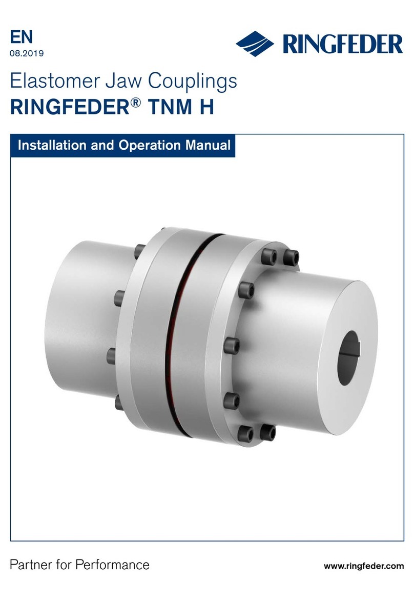
The RINGFEDER® TNS S-St / TNS S-LSt coupling is a torsionally flexible, puncture proof
claw coupling. It compensates for angular, radial and axial shaft misalignments within
defined limits. The coupling transmits torque through elastic buffers loaded in shear. These
buffers come in Perbunan (Pb) or polyurethane (Vk), as standard in Vulkollan red (VkR),
and are connected to each other to form a buffer ring.
This elastic buffer ring dampens shocks and torsional vibrations and is resistant to oil.
Buffer rings made of Perbunan are electrically conductive.
The coupling is suitable for use in every direction of rotation and installation position.
2.1 Intended Application
•The coupling must only be operated in normal industrial atmospheres. Since aggressive
media may attack the coupling components, screws and elastic buffer rings, they repre-
sent a risk for the operational safety of the coupling. Consult RINGFEDER POWER
TRANSMISSION in such cases.
•In order to ensure trouble-free and reliable operation, the coupling has to be sized
according to the design specifications, e.g. according to DIN 740, part 2, (or acc. to
Product Paper & Tech Paper ”Elastomer Jaw Couplings“), with a service factor
appropriate for the service conditions.
•Except for the production of a finish bore with keyway (see 7.2 ‘Finish Bores’), no further
modifications are allowed to be carried out on the coupling.
•The coupling shall only be used and operated within the frame of the conditions as
defined in the performance or delivery contract.
•Any change in the operation conditions or service parameters requires the verification of
the coupling design.
BAWS 001-GBR-1 RINGFEDER® TNS S-St, TNS S-LSt
- 4 -
3 Coupling Marking
3.1 Marking of Buffer Rings
The buffer rings are marked on the face of one buffer element as follows:
- Coupling size and material abbreviation (Vk for Polyurethane or Pb for Perbunan)
- Year of construction
-Pb72 = buffer ring of Perbunan, 72 Shore(A) / black
-Pb82 = buffer ring of Perbunan, 82 Shore(A) / black
-VkB = buffer ring of Polyurethane, 83 Shore(A) / blue
-VkR = buffer ring of Polyurethane, 93 Shore(A) / red
-Vk60D = buffer ring of Polyurethane, 60 Shore(D) white/beige
4 Storage
On receipt of the goods, immediately check that all parts are on hand and are as ordered.
Eventual shipping damages and/or missing parts have to be reported in writing.
The coupling parts can be stored in the delivered state in a dry place under roof at normal
ambient temperatures for a time period of 6 months. Storage for a longer period requires the
application of a long-term preservation. (Please consult RINGFEDER POWER
TRANSMISSION in this respect.) The buffer rings must not be exposed to ozonic media,
direct sun light or intensive light sources with UV light. The air humidity should not exceed
65 %. If the parts are properly stored, the quality characteristics of the elastic buffer rings
remains almost unchanged for up to three years.
Size DA
[mm] h
[mm] z
50 48 12 4
70 70 18 6
85 82 18 6
100 100 20 6
125 121 25 6
145 139 30 6
170 166 30 8
200 194 35 8
230 222 35 10
260 253 45 10
300 294 50 10
360 350 55 12
400 393 55 14
BAWS 001-GBR-1 RINGFEDER® TNS S-St, TNS S-LSt
- 5 -
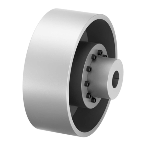
Fig. 1 Construction RINGFEDER® TNS S-St / TNS S-LStt
5 Construction
1 Coupling hub S-St, part 200
1L Long hub S-LSt, part 210
2 Elastic buffer ring, part 020
BAWS 001-GBR-1 RINGFEDER® TNS S-St, TNS S-LSt
This manual suits for next models
1
Table of contents
Other RINGFEDER Industrial Equipment manuals

RINGFEDER
RINGFEDER TNZ ZCA User manual

RINGFEDER
RINGFEDER 4045/G145 User manual

RINGFEDER
RINGFEDER TNM H User manual

RINGFEDER
RINGFEDER TNM GBT Series User manual

RINGFEDER
RINGFEDER GWE 5102 User manual

RINGFEDER
RINGFEDER TNM G User manual

RINGFEDER
RINGFEDER 4045 User manual

RINGFEDER
RINGFEDER 5055 User manual

RINGFEDER
RINGFEDER GWB EKN User manual

RINGFEDER
RINGFEDER TNS SX User manual