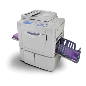
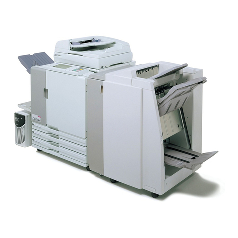
Riso GR 3770 User manual

GR3770
TECHNICAL MANUAL
VERSION1.0
AUGUST, 1997
Copyright : 1997 Riso Kagaku Corporation
All Rights Reserved. This Technical Manual was prepared and
written for the exclusive use of RISO International Group Certi-
fied Dealers. Reproduction and/or transmittal of this material in
any form or by any means, including photocopying or recording of
the information is strictly prohibited without the consent of a mem-
ber of RISO International Group.
RISO INTERNATIONAL GROUP
RISO KAGAKU CORPORATION (JAPAN) RISO DEUTCHLAND GMBH (GERMANY)
RISO, INC. (U.S.A.) RISO FRANCE (FRANCE)
RISO EUROPE LIMITED (U.K.) RISO IBERICA (SPAIN)
RISO HONG KONG (HONG KONG) RISO CANADA (CANADA)
RISO UK (U.K.) RISO CHINA (HONG KONG)
RISO THAILAND LIMITED (THAILAND) RISO AFRICA (SOUTH AFRICA)

GR3770- 1 -
CONTENTS
1. MACHINE SUMMARY
1. Preface ....................................................................................................................................................... 1-1
CAUTION .................................................................................................................................................... 1-2
WARNING ................................................................................................................................................... 1-3
NOTICE ...................................................................................................................................................... 1-4
2. Features of the Risograph GR3770 ........................................................................................................... 1-5
3. Specifications ............................................................................................................................................. 1-6
4. Product Compatibility ................................................................................................................................. 1-7
2. DRUM SECTION
[TheoryofOperation]
1. DrumInsertionErrorPreventiveSystem .................................................................................................... 2-1
2Ink Bottle Detecting System........................................................................................................................ 2-2
3. Ink Supply System ...................................................................................................................................... 2-3
[ Removal ]
1. InkBottleSetSWAssy. ............................................................................................................................... 2-4
3. FLAT BED IMAGE SCANNING SECTION
[TheoryofOperation]
1. Scanner Table Setting System ................................................................................................................... 3-1
2. Stop Position of Image Scanner ................................................................................................................. 3-2
3. Image Scanner Position Detecting System ................................................................................................ 3-3
4. Flat Bed Original Set Confirming System................................................................................................... 3-6
5. Flat Bed Auto Scanning Contrast Adjustment System ............................................................................... 3-7
6. Flat Bed Image Scanning System .............................................................................................................. 3-8
[ Removal ]
1. StageGlass ................................................................................................................................................ 3-10
2. Image Scanner Unit.................................................................................................................................... 3-11
3. Flat Bed Original Detection Sensor and Image Flexible Wire ................................................................... 3-12
4. Flat Bed Read Pulse Motor Unit................................................................................................................. 3-13
5. Original Stopper and Shading Glass ......................................................................................................... 3-14
4. MASTER MAKING SECTION
[ Removal ]
1. Thermal Print Head .................................................................................................................................... 4-1
[ Adjustment ]
1. Thermal Power of Thermal Print Head ....................................................................................................... 4-3
5. MASTER CLAMP & LOADING SECTION
[TheoryofOperation]
1. Clamp Unit Home Positioning System ....................................................................................................... 5-1
2. Clamp Plate Master Release System ........................................................................................................ 5-2
3. Clamp Plate Master Clamp System ........................................................................................................... 5-4

GR3770 - 2 -
[ Removal ]
1. Clamp Unit.................................................................................................................................................. 5-6
2. Disassembling of Clamp Unit..................................................................................................................... 5-7
3. Angle Sensor Ass’y..................................................................................................................................... 5-8
APPENDIX (I)
[TEST MODE]
1. Operation Procedures .................................................................................................................. APX(I)-1
2. Testing Sensor and Switch ........................................................................................................... APX(I)-3
3. Testing Motor and Solenoid ......................................................................................................... APX(I)-4
4. Memory Switch ............................................................................................................................. APX(I)-5
5. Memory Clear and Counter Stop, etc........................................................................................... APX(I)-7
6. Sequential Operation Test ............................................................................................................ APX(I)-8
7. PanelTest ..................................................................................................................................... APX(I)-10
[ ADVICE DISPLAYS ]
1. Trouble Messages (T Display) ..................................................................................................... APX(I)-11
2. Trouble Messages (Others) .......................................................................................................... APX(I)-15
3. Setting Confirmation Messages ................................................................................................... APX(I)-18
4. Change-of-Consumables Messages ........................................................................................... APX(I)-19
APPENDIX (II) DESCRIPTION OF PCB’S
1. Blockchart .................................................................................................................................... APX(II)-1
2. Location of PCBs .......................................................................................................................... APX(II)-2
3. SYSTEM PCB2 ............................................................................................................................. APX(II)-3
4. Image Processing PCB (IPIF) ....................................................................................................... APX(II)-10
5. Motor Control PCB MK2 ............................................................................................................... APX(II)-13
6. Drum Control PCB3...................................................................................................................... APX(II)-15
7. ADF PCB ...................................................................................................................................... APX(II)-17
8. FBIPCB ........................................................................................................................................ APX(II)-19
9. Option PCB AIII ............................................................................................................................. APX(II)-22
10.LCD Control PCB ......................................................................................................................... APX(II)-24
11.Power Supply PCB 100-120V ...................................................................................................... APX(II)-26
12.Power Supply PCB 200-240V ...................................................................................................... APX(II)-28
13.TPH Sub PCB ............................................................................................................................... APX(II)-31

GR3770
1. MACHINE SUMMARY
CONTENTS
1. Preface .............................................................................................................................. 1-1
CAUTION ........................................................................................................................... 1-2
WARNING .......................................................................................................................... 1-3
NOTICE.............................................................................................................................. 1-4
2. Features of the Risograph GR 3770 ................................................................................. 1-5
3. Specifications .................................................................................................................... 1-6
4. Product Compatibility ........................................................................................................ 1-7

MACHINESUMMARY
PREFACE
GR37701 - 1
1. PREFACE
This manual provides Technical Service Information for the RISOGRAPH GR 3770 duplicator. Youareadvised to
use this together with “RA Series” “GR Series” Technical Manual as this “GR 3770” Technical Manual includes
only the items different from the other GR Series machines.
This manual is published as a reference guide for use by RISO Group (RISO Kagaku Corp./RISO, INC./RISO
EUROPE Ltd.) Certified Technical Representatives experienced in duplicator repair and service.
This manual also provides procedures for removing and installing major components. Following these proce-
dures will minimize machine malfunctions. This information and format will also increase technical representa-
tives’ awareness and experience regarding repairs necessary to insure end-user satisfacion.
Ifassistance isrequired, pleasecontact oneof thefollowing:
[ RISO Kagaku Corp. ]
OverseasTechnicalSection,OverseasTechnicalDept.
2-5-1, Akanehama, Narashino-shi, Chiba 275, JAPAN
TEL: (0474) 52-4111 FAX: (0474) 52-3106 TELEX: 252-2298RISO J
[ RISO EUROPE LTD. ]
1230 High Road, Whetstone, London N20 0LH, United Kingdom
TEL: (81) 446-1188 FAX: (81) 446-9547
[ RISO, INC. ]
NOTE: Before attempting to correct machine malfunctions, study the Technical Manual and make sure all
questions and/or concerns have been satisfied. If necessary, please use the Technical Hotline:
TECHNICALHOTLINE
800-578-7476
(EmergencyTechnicalAssistanceOnly!!!)
REFERENCE ADDRESSES FOR
ARISO,INC.
Tech. Support Center
310 Andover Street
Danvers, MA 01923
BRISO,INC. REPAIR DEPT.
310 Andover Street
Danvers, MA 01923
Technical Support Operations Corre-
spondence and Technical Training
Repairs and Warranty Claims

MACHINESUMMARY
CAUTION
GR3770 1 - 2
CAUTION
[ Handling of Lithium Battery ]
• Neverfailtofollowthefollowinginstructionswhenyoudiscardtheusedlithiumbattery.
1. Never let the battery short-circuited.
If the (+) and (−) terminals contact each other or metal materials, the battery will be short-circuited. If the
batteries are collected and stored inorderly or one upon another, the above-mentioned case will occur.
-DANGER-
If the battery is short-circuited, it will heat up and may in some cases explode into fire.
2. Never heat up the battery.
-DANGER-
If you heat the battery up to more than 100°C or put it into the fire, it may burn dangerously or explode.
3. Never disassemble the battery or press it into deformation.
-DANGER-
Ifyoudisassemblethebattery,thegaspouring out of the inside may hurt your throat or the negative lithium
may heat up into fire.
Ifthebatteryispressedintodeformation,theliquidinsidemayleakoutofthesealedpartorthebatterymay
be short-circuited inside an explode.
4. Never fail to keep the battery out of reach of children.
If you put the battery within reach of children, they may swallow it down.
Should they swallow the battery, immediately consult the doctor.
[ Replacement of the Lithium Battery ]
1. The lithium battery must be replaced by a trained and authorized service technician.
2. The battery must be replaced only with the same or equivalent type recommended by the manu-
facturer.
3. Discardusedbatteries according to themanufacturer’sinstructions.

MACHINESUMMARY
WARNING
GR37701 - 3
!! WARNING !!
Important Safety Precautions
1. Always disconnect electrical supply before placing hands in the machine.
1. Toavoid injuries:
Be sure to disconnect the electrical power before disassembling, assembling, or when making adjustments on
the machine.
2. Protection of the machine:
Make sure to turn OFF the power to the machine before plugging or unplugging the electrical connectors, or
when connecting a Meter.
2. Always connect electrical connectors firmly.
1. To avoid electrical failure:
The connectors must be connected firmly together and onto the PCBs.
Press on the ends of the connectors and then on the middle to ensure a firm fit.
2. Protection of the electrical components:
The electrical components may be damaged due to short circuits caused by a loose connector.
FIRST
THEN
Wire harness connector
Press the ends.
Pressthe center, firmly.

MACHINESUMMARY
NOTICE
GR3770 1 - 4
Please be sure to follow the procedures as below in installation :
NOTICE 1 Remove the parts in 5 places as shown in the figures below.
2 Activate the Test mode.
3 Enter No.133 to release the electrical lock.
Caution
Do not turn the power ON with Scanner Unit Securing Plate left unremoved, which may damage the machine.
Press Plate
Securing Block
Securing Plate
Shock Absorbing sheet Styrofoam
Scanner unit securing plate
(1) Remove the securing screw on the Scanner
Unit Securing Plate to release the lock. (2) Place the Scanner Unit Securing Plate into the
left end of the hole, then secure it again.

MACHINESUMMARY
FEATURES
GR37701 - 5
2. FEATURESOFTHERISOGRAPHGR3770
This chapter mainly describes technical features. As for advantages concerning business operation, see the
documents issued by Sales Dept.
The GR3770 is a new type of the GR3750 for which 600dpi has been realized.
Special features of the GR3770 are as follows:
•HIGH-PRECISIONIMAGEACHIEVED BY RESOLUTION OF 600dpi
• Adoption of Optical Image Scanner
•Due to increased size of the image scanner, it is fixed for shipment.
⇒Forrelease,shiftthefixingmetal and execute Tst Mode No.133. (Theinstructionsheetisattachedtothe
machine.)
•Due to increased size of the image scanner, the FB original detection sensor is hidden in FB/HP sensor
position. Therefore, the image scanner is shifted for detection of an original copy.
•ADOPTION OF HIGH-DENSITY INK/DEDICATED MASTER
• Use of High-Density Ink (HD ink) Developed to Achieve 600dpi Performance.
•A special drum dedicated to the GR3770 is mounted which is applicable to the HD ink bottle. (The ink bottle
set SW is added.)
•The Clamp gear has been increased in strength to meet the change in the clamp unit.
•Although the present color drum is useable, the clamp plate base needs to be changed because of the
abovementioned grounds.
•Use of Dedicated Master (77W) Developed to Achieve 600dpi Performance.
•Master roll diameter has been increased due to looser winding in comparison with the present master
(76W).
•Master flange size has been increased (due to the above ground.)
•INCREASE IN PHOTO IMAGE REPRODUCIBILITY THROUGH USE OF CONTRAST ENHANCE MODE
•As against the adjustment in γcompensation which was available with the image processing PCB,
adjustment in two stages (three stages if including “Normal”) has been made available at the users’ level.
•REDUCTIONIN MASTER-MAKINGTIME THROUGHUSE OFBOOK MODE
•Pre-scanning has been eliminated through use of realtime trimming.
(However, the overall master-making time was increased due to adoption of 600dpi.)
•CLAMPINGWORKSTABILIZED AS CLAMPUNITHAS BEEN CHANGED
•The clamp unit UP & Down movement can be also drived by rotation of the clamp motor as well as
opening/closing movement of clamp plate.
•“T14” is not displayed even if the clamp unit is lowered manually.
•Mounting on the present models has not been enabled as yet.
•OTHERS
•The original stage glass and the original stopper are each independently provided.
•The write pulse motor is adjustable in speed.
•Applicable to New Computer I/F Rev.5.xx. (Not applicable to Rev.4xx.)
•Applicable to New Sorter I/F specification. (Not applicable to the former Sorter specification.)

MACHINESUMMARY
SPECIFICATIONS
GR3770 1 - 6
3. Specifications
GR3770
•Processing
•Timeto FirstCopy
•Print Speed
•Scanning Resolution
•OriginalType
•Original Size
•Paper Size
•OriginalWeight
•PaperWeight
•Image Area
•Paper Capacity
•OptionalADF Capacity
•MachineWeight
•Dimensions
[ W ×D ×H ]
•Power Source
<Requirements>
•Reduction Parameters
•Enlargement Parameters
•Zooming Parameters
•Features
•Print Colors
•Optional Accessories
High-speed automatic digital scanning
Fully automatic, thermal screening duplicating system
Ledger or A3 original / Approx. 29 seconds
Letter or A4 original / Approx. 22 seconds
5 selectable print speeds (60, 80, 100, 110, 120 sheets/min.)
600 dpi
Bound documents or sheets
-For the Stage Glass:
Max./A3 (297 ×420mm) or Ledger (11 ×17 inch)
Min./Business card (50 ×90mm) or 2 ×3 1/2 inch
-In the optional ADF Unit:
Max./A3 (297 ×420mm) or Ledger (11 ×17 inch)
Min./A6 (100 ×148mm) or 4 x 6 inch
Max./A3 (297 ×420mm) or Ledger (11 ×17 inc)
Min./A6 (100 ×148mm) or 4 ×6 inch
-For the Stage Glass:
10 kg or less
-In the optional ADF Unit:
Max./110 g/m2
Min./50 g/m2
Max./210 g/m2
Min./46 g/m2
A3 Drum/290 ×412mm
Ledger Drum/10.7 ×16.5 inch
1000 sheets in feed and receiving tray
[ Based on 64 g/m2paper ]
50 originals
Approx.116 kg
In use/1316 ×669 ×634mm
In storage/753 ×669 ×634mm
Picture Model :220 to 240 VAC, 50/60 Hz <2.0A>
USA Model :120 VAC, 60 Hz <5.0A>
Metric Models:110 VAC, 60 Hz <5.0A> - 110-V model
220 to 240 VAC, 50/60 Hz <2.0A> - 220-V model
4 selectable reductions (94%, 87%, 82% and 71%)
[ 94%, 77%, 75% and 66% in USA models ]
3 selectable enlargements (141%, 122% and 116%)
[ 141%, 127% and 121% in USA models ]
50% to 200%
LCD monitor, Print speed/density control, Confidential mode, Two-up print-
ing, Book document processing, Programmed printing, Memory mode, Con-
trast enhance mode, Dot screen mode, Interface capabilities, Photo mode,
Automatic idle and Automatic scanning contrast adjustment
Black, blue, red, green, brown, yellow and etc.
Color drum unit, A4 drum unit, ADF III(S) unit, Digitizer III(S), TM2500 sorter,
TM5000sorter,SheetfeederSF3000,Key/Cardcounter III(S), Job separator
III and Computer interface


MACHINESUMMARY
PRODUCTCOMPATIBILITY
GR37701 - 7
4. PRODUCT COMPATIBILITY
Accessory Compatibility chart
APPLICABLE MODEL GR3770 GR3750 GR2750 GR2710 GR1750 GR1700
PRODUCT
GR3770 Black Drum
GR Color Drum A3
GR Drum B4/A4
GR3770 Black A4 WIDE Drum
GR Color Drum A4 WIDE
ADFUNITIII(S)
ADFUNITIII
Sheet Feeder SF3000
TM5000 Sorter
TM2400 Sorter
TM2500 Sorter
DIGITIZERIII(S)
DIGITIZERIII
Key/Card Counter III (S)
Key/Card Counter III
Job Separator III
GRPrecisionStackingTray
Interface Board III (S)
Interface Board III
: Fully Compatible
: Color Drum only
: Not Compatible

MACHINESUMMARY
PRODUCTCOMPATIBILITY
GR3770 1 - 8
Consumables Compatibility Chart
APPLICABLE MODEL GR3770 GR3750 GR2750, 2710, 1750, 1700
PRODUCT
RISOGRAPHGR MASTER 77W
RISOGRAPHGR MASTER 76W
RISOGRAPHGR MASTER 75
RISOGRAPHGRINKHD(BLACK)
RISOGRAPHGR INK (BLACK)
RISOGRAPHGR INK (RED)
RISOGRAPH GR INK (BLUE)
RISOGRAPHGR INK (BROWN)
RISOGRAPHGR INK (GREEN)
RISOGRAPHGR INK (YELLOW)
RISOGRAPHGRINK(GRAY)
RISOGRAPHGRINK(LIGHTGRAY)
RISOGRAPHGRINK(MARINERED)
RISOGRAPHGRINK(BRIGHTRED)
RISOGRAPHGRINK(BURGUNDYRED)
RISOGRAPHGRINK(FEDERALBLUE)
RISOGRAPHGRINK(MEDIUMBLUE)
RISOGRAPH GR INK (PURPLE)
RISOGRAPHGRINK(TEAL)
RISOGRAPHGRINK(FLATGOLD)
RISOGRAPHGRINK(ORANGE)
RISOGRAPHGRINK(HUNTERGREEN)
* ORDER COLORS

GR3770
2. DRUM SECTION
CONTENTS
[TheoryofOperation ]
1. DrumInsertionErrorPreventiveSystem ..................................................................... 2-1
2. Ink Bottle Detecting System......................................................................................... 2-2
3. Ink Supply System ....................................................................................................... 2-3
[ Removal ]
1. Ink Bottle Set SW Ass’y................................................................................................ 2-4

DRUMSECTION
THEORYOF OPERATION
GR37702 - 1
1. THEORYOFOPERATION
1. DRUM INSERTION ERROR PREVENTIVE SYSTEM
The drum cover (lower) differs in shape so that the GR3770 dedicated drum is not inserted into the GR3750
machine by mistake. On the other hand, GR3750 drum can be inserted into the GR3770, thus enabling common
use of the color drum.
GR3770 Drum GRDrum
GR 3770 GR Machine

DRUMSECTION
THEORYOF OPERATION
GR3770 2 - 2
2. INK BOTTLE DETECTING SYSTEM
Ink Bottle SWs 1/2/3 as well as Ink Bottle SW-HD detects if an ink bottle appropriate for the drum has been set in
position.
*If Ink Bottle SW has not been pushed, “INSTALL INK CARTRIDGE” message is displayed.
*If Ink Bottle SW has been pushed in wrong combination, “WRONG-TYPE INK CARTRIDGE INSTALLED”
message is displayed.
Ink bottle SW
Ink bottle SW-HD
Normal bottle HD bottle
ON
Test Mode No.55 Bottle set SW1
No.56 Bottle set SW2
No.57 Bottle set SW3
No.17 Bottle set SW-HD

DRUMSECTION
THEORYOF OPERATION
GR37702 - 3
3. INK SUPPLY SYSTEM
As the Main shaft catch rotates, the squeegee roller and the ink driving shaft are turned. There is a slight gap
between the squeegee roller and the doctor roller, through which ink, applied on the squeegee roller, is supplied
inside the drum. A swirl of ink is produced on the driving shaft and is rotated along with the shaft, where the swirl
is maintained in consistent size. As ink is used in printing and the ink swirl gets apart from the ink sensor, the ink
motor is turned ON so that ink is sucked from the ink bottle by the ink pump until ink comes in contact with the ink
sensor. Further, ink is supplied through the ink distributor on to the squeegee roller.
Ink held by the ink distributor is all supplied to the squeegee from the elbows at both ends of the distributor.
Occurrence of overflow of ink in the drum is detected by the overflow sensor.
Linking disc
Piston
Inking motor
Elbow
Main shaft catch
Squeegee pulley
Ink driving shaft axis
Overflow sensor (short)
Ink sensor (long)
Ink driving shaft
Ink distributor
Doctor roller
Squeegee roller
Elbow
Piston Valve
Coil spring
RC Coil spring
Squeegee roller
Ink distributor
Inksensor
Doctor roller

DRUMSECTION
REMOVAL
GR3770 2 - 4
2. REMOVAL
1. INK BOTTLE SET SW ASSY.

GR3770
3. FLAT BED IMAGE SCANNING SECTION
CONTENTS
[Theory of Operation ]
1. Scanner Table Setting System .................................................................................... 3-1
2. Stop Position of Image Scanner .................................................................................. 3-2
3. Image Scanner Position Detecting System................................................................. 3-3
4. Flat Bed Original Set Confirming System.................................................................... 3-6
5. Flat Bed Auto Scanning Contrast Adjustment System................................................ 3-7
6. Flat Bed Image Scanning System ............................................................................... 3-8
[ Removal ]
1. Stage Glass ............................................................................................................... 3-10
2. Image Scanner Unit................................................................................................... 3-11
3. Flat Bed Original Detection Sensor and Image Flexible Wire .................................. 3-12
4. Flat Bed Read Pulse Motor Unit................................................................................ 3-13
5. Original Stopper and Shading Glass ........................................................................ 3-14

FLAT BED IMAGE SCANNING SECTION
THEORY OF OPERATION
GR37703 - 1
1. THEORY OF OPERATION
1. SCANNER TABLE SETTING SYSTEM
Flat Bed Set SW detects if the scanner table has been set in position.
When the scanner table is left open, the interlock switch neither for the thermal print head nor for the main motor
can be pushed, where power supply to the main motor and to the thermal head is cut off.
* If Scanner table Set Switch or Interlock Switch (for main motor) has not been pressed, “CLOSE SCANNER
TABLE” message is displayed.
Scanner table set switch
Interlock switch
(for Main motor)
Interlock switch
(for Thermal print head)
TestMode No.21 : Scanner table set switch
No.39 : Inter lock switch
Scanner table

FLAT BED IMAGE SCANNING SECTION
THEORYOFOPERATION
GR3770 3 - 2
2. STOP POSITION OF IMAGE SCANNER
Positions for the image scanner to stop include the following four:
• Home position (Image scanner home position sensor position)
• Original detecting position
• ADF shading position (ADF shading sensor position)
• ADF read-in position
* The correct Home position sensor position is in the Home position sensor ON →OFF position.
* The correct ADF shading sensor position is 1mm apart from the ADF shading sensor OFF →ON position when
the image scanner has moved toward scanning.
Image scanner ADF shading sensor
Image scanner home
position sensor
Home position
(Home position sensor position) ADF shading position
(ADF shading sensor position)
Home positioning direction
(HP)
Scanning direction
Original detecting position ADF read-in position
60
mm120 mm
474 mm
This manual suits for next models
1
Table of contents
Other Riso Printer manuals

Riso
Riso ComColor FW5230 User manual

Riso
Riso RZ1090 User manual

Riso
Riso CV1200W User manual

Riso
Riso ComColor FT Series User manual

Riso
Riso ComColor 9150 Original instructions

Riso
Riso Comcolor Series Service manual

Riso
Riso HC5500 User manual

Riso
Riso GR2750 User manual

Riso
Riso HC5500 User manual

Riso
Riso Comcolor Series User manual

Riso
Riso GOCCOPRO QS200 User manual

Riso
Riso ComColor GL Series User manual

Riso
Riso SF Series User manual

Riso
Riso CZ180 Series User manual

Riso
Riso 9050 User guide

Riso
Riso HC5500T User manual

Riso
Riso ComColor 9150 User guide

Riso
Riso RN SERIES User manual

Riso
Riso MiScreen Manual

Riso
Riso Comcolor X1 Series User manual