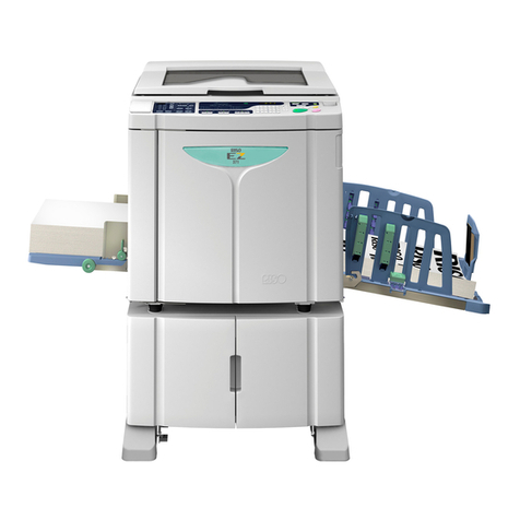
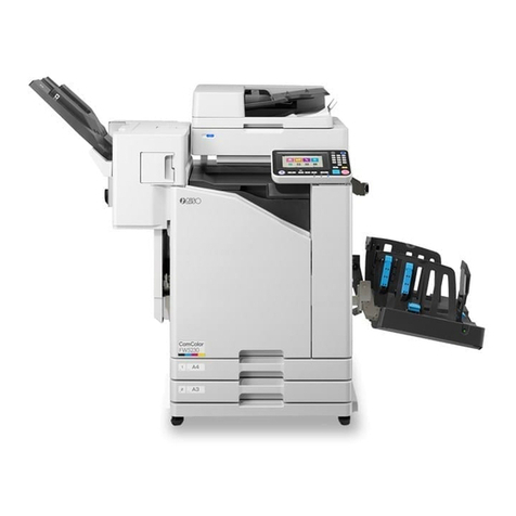
Riso RN SERIES User manual

RISO INTERNATIONAL GROUP
RISO KAGAKU CORPORATION (JAPAN) RISO DEUTSCHLAND GMBH (GERMANY)
RISO, INC. (U.S.A.) RISO FRANCE (FRANCE)
RISO EUROPE LIMITED (U.K.) RISO IBERICA (SPAIN)
RISO HONG KONG (HONG KONG) RISO CANADA (CANADA)
RISO UK (U.K.) RISO ZHUHAI (HONG KONG)
RISO THAILAND LIMITED (THAILAND) RISO AFRICA (SOUTH AFRICA)
Copyright : 2000 Riso Kagaku Corporation
All Rights Reserved. This Technical Manual was prepared
and written for the exclusive use of RISO International Group
Certified Dealers. Reproduction and/or transmittal of this
material in any form or by any means, including photocopying
or recording of the information is strictly prohibited without the
consent of a member of RISO International Group.
VERSION 1.0
JULY, 2000
RN
SERIES
TECHNICAL MANUAL

IndeInde
IndeInde
Indexx
xx
x
Chapter 1 Maintenance
Chapter 2 Machine Summary
Chapter 3 Machine Drive Section
Chapter 4 First Paper Feed Section
Chapter 5 Second Paper Feed Section
Chapter 6 Press Section
Chapter 7 Paper Ejection System
Chapter 8 Print Drum Section
Chapter 9 Master Clamp Section
Chapter 10 Master Removal Section
Chapter 11 F.B. Original Scanning Section
Chapter 12 A.D.F. Original Scanning Section
Chapter 13 Master Making Section
Chapter 14 Timing Charts
Chapter 15 Panel Messages
Chapter 16 Test Modes
Chapter 17 User Mode Settings
Chapter 18 Miscellaneous Precautions
Chapter 19 Description of P.C.B’s

1 – 1
RN (Version 1.0)
CHAPTER 1: MAINTENANCE
Contents
1. Preface ......................................................................................................................1-2
CAUTION...................................................................................................................1-3
WARNING .................................................................................................................1-4
2. Work Precautions .....................................................................................................1-5
3. Exterior Cover Removal ............................................................................................1-8
4. Controller (RISORINC2) and System PCB ........................................................... 1-13

1 – 2
RN (Version 1.0)
CHAPTER 1. MAINTENANCE
1. Preface
This manual provides Technical Service Information for the RISOGRAPH model RN series.
This manual is published as a reference guide for use by RISO Group (RISO Kagaku Corp./
RISO,INC./RISO EUROPE Ltd.) Certified Technical Representatives experienced in duplicator repair
andservice.
This manual also provides procedures for removing and installing major components. Following these
procedures will minimize machine malfunctions. This information and format will also increase
technical representatives' awareness and experience regarding repairs necessary to insure end-user
satisfaction.
PREFACE

1 – 3
RN (Version 1.0)
CHAPTER 1. MAINTENANCE
[Handling of Lithium Battery]
- Never fail to follow the following instructions when you discard the used
lithium battery.
1. Never let the battery short-circuited.
If the (+) and (-) terminals contact each other or metal materials, the battery will
be short-circuited. If the batteries are collected and stored inorderly or one upon
another, the above-mentioned case will occur.
- DANGER -
If the battery is short-circuited, it will heat up and may in some cases explode into
fire.
2. Never heat up the battery.
- DANGER -
If you heat the battery up to more than 100°C or put it into the fire, it may burn
dangerously or explode.
3. Never disassemble the battery or press it into deformation.
- DANGER -
If you disassemble the battery, the gas pouring out of the inside may hurt your
throat or the negative lithium may heat up into fire.
If the battery is pressed into deformation, the liquid inside may leak out of the
sealed part or the battery may be short-circuited inside an explode.
4. Never fail to keep the battery out of reach of children.
If you put the battery within reach of children, they may swallow it down.
Should they swallow the battery, immediately consult the doctor.
[Replacement of the Lithium Battery]
1. The lithium battery must be replaced by a trained and authorized service
technician.
2. The battery must be replaced only with the same or equivalent type
recom- mended by the manufacturer.
3. Discard used batteries according to the manufacturer’s instructions.
CAUTION
CAUTION

1 – 4
RN (Version 1.0)
CHAPTER 1. MAINTENANCE
!! WARNING !!
Important Safety Precautions
1. Always disconnect electrical supply before placing hands in the
machine.
I. To avoid injuries:
Be sure to disconnect the electrical power before disassembling, assembling,or when
making adjustments on the machine.
II. Protection of the machine:
Make sure to turn OFF the power to the machine before plugging or unplugging the
electrical connectors, or when connecting a Meter.
2. Always connect electrical connectors firmly.
I. To avoid electrical failure:
The connectors must be connected firmly together and onto the PCBs.
Press on the ends of the connectors and then on the middle to ensure a firm fit.
II. Protection of the electrical components:
The electrical components may be damaged due to short circuits caused by a loose
connector.
Wire harness connector
FIRST
THEN
Press the ends.
Pressthecenter,firmly.
WARNING

1 – 5
RN (Version 1.0)
CHAPTER 1. MAINTENANCE
WORK PRECAUTIONS
2. Work Precautions
Inspection
If you discover any defects or problems during an inspection, fix the problems or if necessary take
steps such as replacing a part.
Removal
Check the problem area. At the same time, examine the cause of the problem and determine
whether the part needs to be removed or disassembled. Next proceed according to the proce-
dures presented in the Technical Manual. In cases where, for example, it is necessary to disas-
semble areas with large numbers of parts, parts which are similar to each other, or parts which are
the same on the left and right, sort the parts so that you do not mix them up during reassembly.
(1) Carefully sort the removed parts.
(2) Distinguish between parts which are being replaced and those which will be reused.
(3) When replacing screws, etc., be sure to use the
specified sizes.
Assembly and Installation
Unless specified otherwise, perform the removal proce-
dures in reverse during assembly and installation. In
cases where protrusions or holes are provided to assist
in positioning parts, use them for accurate positioning
and securing.
(Protrusions and holes for positioning parts Half
pierce section)
Tools
Using tools other than those specified can lead to injury
or damage screws and parts. Have all the tools neces-
sary for the work available.
<Standard Tool list>
Type Tip size Shaft length, etc.
No. 2 (250mm)
No. 2 (100 mm-150 mm)
No. 2 (stubby type)
No. 1 (75 mm-100 mm)
6 mm (100 mm-150 mm)
3 mm (100 mm-150 mm)
1.8 mm (precision type)
8 mm (100 mm-150 mm)
7 mm (100 mm-150 mm)
2.5 mm
5 mm 5.5 mm 7 mm
8 mm 10 mm 13 mm
Monkey
5.0 mm
4.0 mm
3.0 mm
2.5 mm
2.0 mm
1.5 mm
Phillipsscrewdriver
Standardscrewdriver
Nutdriver
(boxdriver)
Highfrequencydriver
Spanners
(maybedouble-ended)
Hex wrenches
Type Remarks
Steel scale 150 mm
Feelergauge
Radial cutting pliers
Pliers
Nipper
Small flashlight
Multimeter
Solderingiron 20 W-30 W
File Flat, round
- ( 2 pieces required )

1 – 6
RN (Version 1.0)
CHAPTER 1. MAINTENANCE
Electrical system work
• Afterremovingwirebundles,fastenthem
with wire bundle bands (bar lock ties) so
that they will not sag.
• When installing parts, be careful to avoid
pinching or damaging the wire bundles.
• Ifa fuse blows, alwaysreplaceitwith one
with the specified capacity. Using a fuse
with a larger capacity can not only dam-
age parts, but may cause fires.
• Be careful not to drop image scanners,
thermal print heads, and other sensors
as they can be easily damaged.
Switch types
• Microswitchesmaybedividedbetweennor-
mallyopen(NO)typesandnormallyclosed
(NC) types.
With an NO connection, an internal con-
tact is connected when the switch actua-
tor is pressed.
With an NC connection, an internal con-
tact is disconnected when the switch ac-
tuator is pressed.
• Magnetic lead switches are switches in
which an internal contact is connected
in reaction to the magnetic force of a
magnet.
Sensor types
• Photo-electric sensors may be broadly
divided into the following four types: in-
terrupttypes (U-shaped), actuator types,
reflective types, and transmittive types.
• Magneticsensors use Hall ICs, whichre-
act to the magnetic force in magnets.
• Alwaysturnoffthepowerbeforeplugging
or unplugging sensor connectors.
WORK PRECAUTIONS

1 – 7
RN (Version 1.0)
CHAPTER 1. MAINTENANCE
Installation location
• Do not install the machine in any of the following locations.
(1) Those subject to direct sunlight or any bright location such as by a window (If you must
install in such a location, put a curtain or the like over the window.)
(2) Those where the temperature changes drastically
(3) Those that are too hot, cold, humid, or dry
RECOMMENDED:
Temperaturerange:15° centigrade - 30° centigrade
Humidity range: 40% - 70% No condensation allowed
(4) Those with radiant heat sources and any locations in the direct path of air from air condition-
ers, heaters
(5) Any poorly ventilated location
(6) Dusty atmosphere
(7) Any tilted location
(Installation height difference: 10 mm max. front - rear, 10 mm max. left - right)
Electrical connection
• Plug the plug securely into the socket so that there is no problem with the contact in the power
supply plug section.
• Do not use any triplets or extension cords.
• Do not allow any other machine to stand on or crush the power cord.
Ground connection
• Always ground this machine to prevent electrical shock in the unlikely event of electrical
leakage.
WORK PRECAUTIONS

1 – 8
RN (Version 1.0)
CHAPTER 1. MAINTENANCE
3. Exterior Cover Removal
1. Bring the Print Cylinder to Position-A and remove the Print Cylinder from the machine.
2. Turn off the power and remove the power cord from the machine.
FRONTCOVER
Remove mounting screws (M4x8: 2 pcs) from the Hinge, and remove the Hinge.
The Front Cover comes off the machine.
Frontcover Hinge
FRONTFRAMECOVER
Remove mounting screws (M4x8: 7 pcs) and remove the Front Frame Cover.
Frontframecover
EXTERIOR COVER REMOVAL

1 – 9
RN (Version 1.0)
CHAPTER 1. MAINTENANCE
EXTERIOR COVER REMOVAL
REARCOVER
Remove mounting screws (M3x5: 2pcs) of the Connector Lock of the Controller and open the
Connector Locks flat against the Controller.
Remove screws (M4x8: 4 pcs) and remove the Rear Cover.
Rearcover
Connector lock
MASTER REMOVAL LOWER COVER
Remove the Master Disposal Box.
Remove screws (M4x8: 4 pcs) and remove the Master Removal Lower Cover.
Masterremovallowercover

1 – 10
RN (Version 1.0)
CHAPTER 1. MAINTENANCE
EXTERIOR COVER REMOVAL
STAGECOVER
Remove mounting screw (M4x10: 1 pc) from each of the two Hinges of the Stage Cover, and then as
shown on the photograph, attach those screws in the secrew holes behind.
Remove screw (M4x8: 1 pc) on the Scanner Unit Cover (rear) to detach the Ground Wire from the
machine, and then lift the Stage Cover off the machine.
Stagecover
Groundwire
Hinge ScannerUnitCover(rear)

1 – 11
RN (Version 1.0)
CHAPTER 1. MAINTENANCE
SCANNERUNITCOVER(LEFT)
Remove mounting screw (M4x8: 4 pcs) and remove the Scanner Unit Cover (left).
Scanner unit cover (left)
SCANNERUNITCOVER(REAR)
Remove the Stage Cover.
Remove mounting screw (M4x8: 4 pcs) and remove the Scanner Unit Cover (rear).
Scanner unit cover (rear)
EXTERIOR COVER REMOVAL

1 – 12
RN (Version 1.0)
CHAPTER 1. MAINTENANCE
SCANNERUNITCOVER(FRONT)
Remove mounting screw (M4x8: 3 pcs) and remove the Scanner Unit Cover (front).
EXTERIOR COVER REMOVAL
Scanner unit cover (front)
SCANNERUNITCOVER(RIGHT)
Remove Scanner Unit Cover (front) and Scanner Unit Cover (rear).
Remove mounting screw (M4x8: 2 pcs) and remove the Scanner Unit Cover (right).
Scanner unit cover (right)

1 – 13
RN (Version 1.0)
CHAPTER 1. MAINTENANCE
EXTERIOR COVER REMOVAL
4. Controller (RISORINC2) and SYSTEM PCB
CONTROLLER(RISORINC2)
Remove the Rear Cover.
Disconnect three connectors from the Controller (1 on the top and 2 on the bottom of the Controller).
Remove screws (M3x6: 2 pcs), and pull the Controller a little bit to the front, just enough to clear the
half-pierce, and slide the Controller out of the machine.
[Precautions on Reassembly]
Place the Controller on top of the System PCB Support Bracket A, and push it in.
Half-pierce
Controller
(RISORINC2)
System PCB support bracket A

1 – 14
RN (Version 1.0)
CHAPTER 1. MAINTENANCE
EXTERIOR COVER REMOVAL
SYSTEM PCB
Remove the Rear Cover.
Remove screws (M3x5: 1 pc), and remove the Wire Harness Support Plate.
Disconnect all the Connectors from the System PCB, remove screws (M3x5: 6 pcs), and then remove
the System PCB together with the System PCB Support Bracket B.
[Precautions on Reassembly]
Attach the Wire Harness Support Plate while pushing it down against the wire harness (flat cable) to
hold the wire harness firmly in position.
Wire harness support plate
Flat cable (wire harness)

1 – 15
RN (Version 1.0)
CHAPTER 1. MAINTENANCE
SYSTEM PCB SUPPORT BRACKET A
Unplug the connector of the FB Junction Wire Harness from the Junction COnnector, and then detach
the Junction Connector from the System PCB Support Bracket A.
Remove seven Snap Bands from the System PCB Support Bracket A.
Remove screws (M4x6: 5 pcs) and detach the System PCB Support Bracket from the machine.
EXTERIOR COVER REMOVAL
Snapband FB Junction Wire HarnessJunctionConnector
System PCB support bracket A
Snapband
Snapband

1 – 16
RN (Version 1.0)
CHAPTER 1. MAINTENANCE
[Memo]

2 – 1
RN (Version 1.0)
CHAPTER 2: MACHINE SUMMARY
Contents
1. Specifications (Metric Model)....................................................................................1-2
2. Specifications (Inch Model) ......................................................................................1-6

2 – 2
RN (Version 1.0)
CHAPTER 2. MACHINE SUMMARY
1. Specifications (Metric Model)
SPECIFICATIONS (METRIC MODEL)
Reference only
Table of contents
Other Riso Printer manuals

Riso
Riso ComColor FT Series User manual

Riso
Riso GR 3770 User manual

Riso
Riso SF EII Series User guide

Riso
Riso ComColor 9150 Original instructions

Riso
Riso ComColor FW Series User manual

Riso
Riso Comcolor X1 Series User manual
Riso
Riso ComColor GL Series User manual

Riso
Riso 9050 User guide

Riso
Riso CV1200W User manual

Riso
Riso ComColor FW Series Original instructions

Riso
Riso RZ Series User manual

Riso
Riso HC5500 User manual

Riso
Riso GOCCOPRO 100 User manual

Riso
Riso RZ9 Series User manual

Riso
Riso RISOGRAPH RN2000 User manual

Riso
Riso ComColor FW Series User manual
Riso
Riso MZ870 User manual

Riso
Riso 9450 User manual

Riso
Riso ComColor FT Series User manual

Riso
Riso Comcolor Series User manual