Channel Delete
1. In channel mode, press [UP] / [DN] to choose a unwanted channel.
2. Hold [FUN] and [V/M] key for over 1 second, the current channel will be deleted, the radio emit
a prompt and jump to next working channel.
SHORTCUT OPERATION
Squelch Off / Squelch Off Momentary
SQL key programmed as Squelch Off or Squelch Off Momentary to monitor the weak signal.
1. Squelch Off: Press [SQL] key to disable squelch, press [SQL] key again to resume squelch.
2. Squelch Off Momentary: Press [SQL] key to disable squelch, release key to resume squelch.
» The above functions should be set in program software.
Squelch Level Setup
This function use for setting RX signal strength, the calling will be heard only when reach set level,
otherwise the radio will keep mute.
1. In standby, hold [SQL] key, then short press [UP]/[DN] or turn VOL Knob, the LCD displays
current squelch level.
2. Press [UP]/[DN] or turn VOL knob to choose wanted squelch level.
3. Press any key to confirm and exit.
Frequency Scan
In frequency (VFO) mode, this function is designed to monitor signal of all frequency points under
each step size.
1. In VFO mode, short press [SCA] to start frequency scan.
2. Short press [UP] or [DN] to change scan direction.
3. Short press [UP]/[DN] key or any other key except the volume knob to exit scan.
Channel Scan
In channel mode, this function is used to monitor signal in all channels.
1. In channel mode, Press [SCA] key start channel scan.
2. Short press [UP]/[DN] key to change scan direction.
3. Short press [UP]/[DN] key or any other key except the volume knob to exit scan.
Scan Skip
In channel mode, separately short press [FUN] key and [SCA] key to add or delete a scan channel.
1. Decimal point between frequency's ten digit and unit digit disappears, the current channel added
to scan list. this channel will be scanned when scan function start.
2. Decimal point display between frequency's ten digit and unit digit, the current channel is deleted
from scan list, this channel will not be scanned when start scan function.
CTCSS/DCS Encode and Decode Setup
Separately short press [FUN] key and [SQL] key to enter CTCSS/ DCS encode/decode menu,
repeatedly short press [SQL], to set CTCSS/DCS encode/decode for current channel.
1. When the LCD displays T, means current channel set with CTCSS encode, press [UP]/[DN] key
or turn VOL knob to choose wanted encode.
2. When the LCD displays CT, means current channel set with CTCSS encode/decode, press
[UP]/[DN] key or turn VOL knob to choose wanted CTCSS decode.
3. When the LCD displays DCS, means current channel set with DCS encode/decode, press
UP/DN key or turn VOL knob to choose wanted DCS encode/decode.
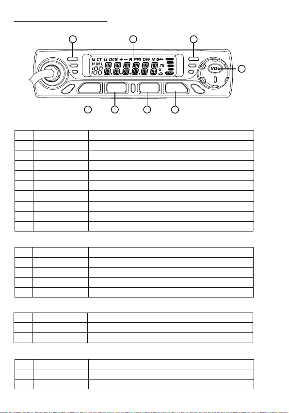
» The display voltage range is from 9V to 17V, the display data is a rough data, if you need
exactly data pls use the voltmeter to test.
Adjusting the Volume
When the transceiver in power on, turn VOL knob, the LCD display VOL-XX, XX means volume
level, can increase or decrease the volume, turn clockwise VOL knob can increase the volume, turn
anticlockwise VOL knob to decrease volume. When set the volume as 1st level, then the transceiver
in mute status.
Switch Between VFO and Channel Mode
In standby, press V/M until LCD appears M. this indicates the radio is in channel mode. Repeate
above operation to switch between frequency mode(VFO) and channel mode.
Adjusting Frequency/Channel
1. In frequency mode, Short press [UP] or [DN] key to increase or decrease frequency. Hold [UP]
or [DN] to fast increase or decrease frequency. Short press [VOL], the MHz will flash, hold [UP]
or [DN] key will change the frequency move by 1 MHz. Press [VOL] key again, the MHZ will
flash, hold [UP]/[DN] key will change the frequency move by 10MHZ, press any key exit this
mode.
» 2.5K, 5K, 6.25K, 10K, 12.5K, 20K, 25K, 30K and 50K total nine step size available for
this radio.
2. In channel mode, short press [UP] or [DN] key to increase or reduce channel by one step. Hold
[UP] or [DN] key to fast increase or reduce channel.
Receiving
When the channel you are operating being called, the screen shows BUSY icon and field strength.
The green RX indicator light on, in this way you can hear the calling.
» If the transceiver has set at higher squelch level, it may fail to hear the calling.
If the transceiver LCD display BUSY icon and field strength, the green LED Rx indicator flashes,
but can not hear the calling, it means has receive matching carrier but with unmatching signaling
(Pls reference CTCSS/DCS encode and decode for operation).
Transmitting
Hold [SQL] key to monitor for a while, to confirm the current channel is not busy, then release
[SQL] key and back to standby state . Hold [PTT] key and speaker into microphone. Hold the
microphone approximately 2.5-5.0cm from your lips and speak into the microphone in your normal
speaking voice to get best timbre.
» Hold PTT key, the LED lights red and power strength show in the screen, indicates it is
transmittin g, release PTT to receive.
Channel Edit
1. In VFO mode, press [UP]/[DN] or [VOL] to choose wanted frequency.
2. Press [FUN] key+ [SQL] to enter CTCSS/DCS setup. Press [UP]/[DN] or [VOL] to select desired
signaling.
3. Enter channel menu No 1-10 and choose related setup.
4. Press [FUN] key, the LCD displays Ficon, if the channel number flash means current channel
number is valid. If Micon flashes means current channel number is empty.
5. Press [UP]/[DN] key or turn VOL knob choose wanted channel number.
6. Press [V/M] key store the channel, the decimal point icon disappear, the channel number no flash
and emit a prompt, it means the channel stored success.
910