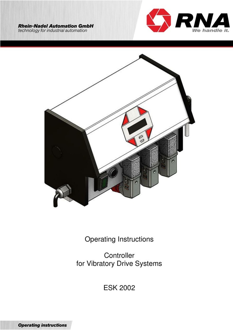
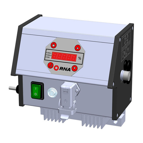
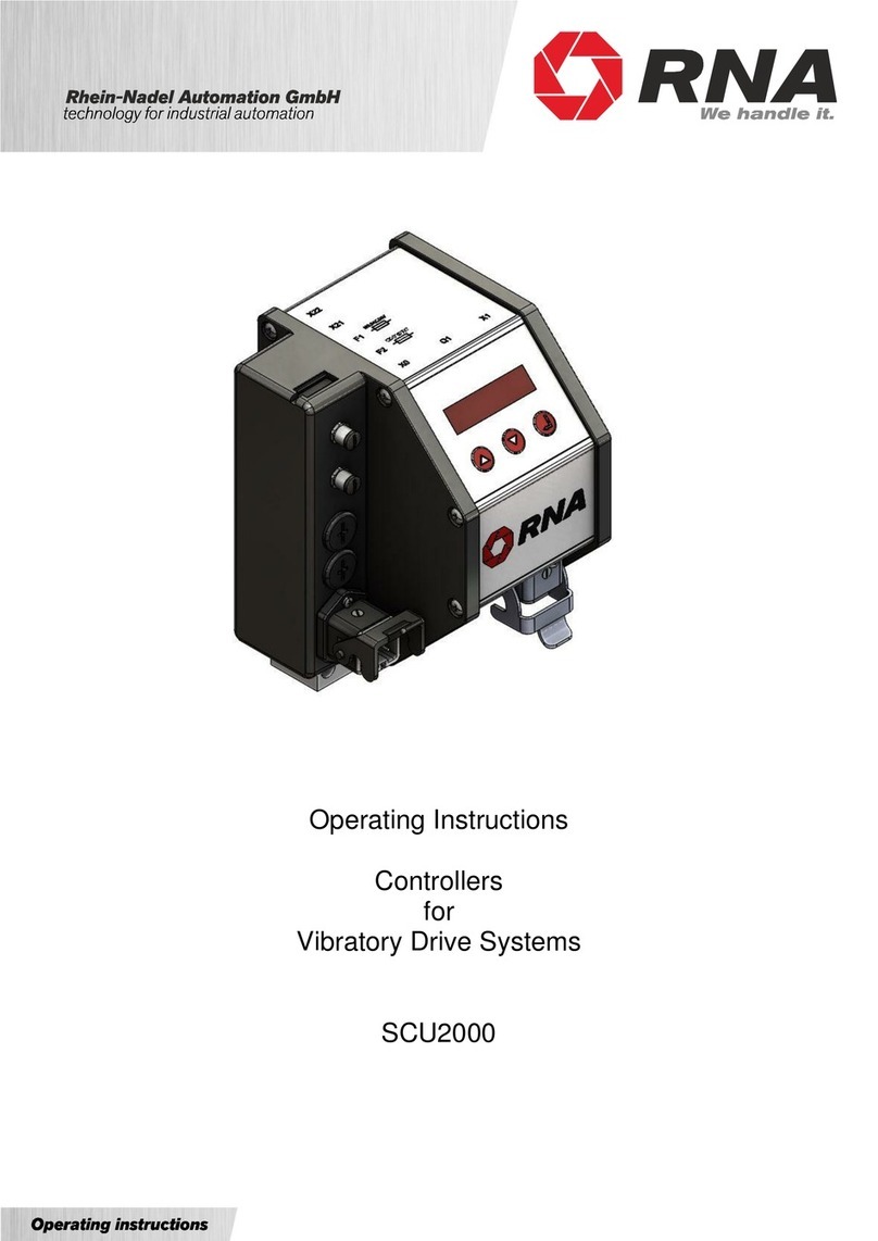
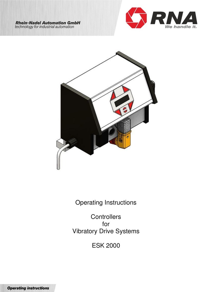
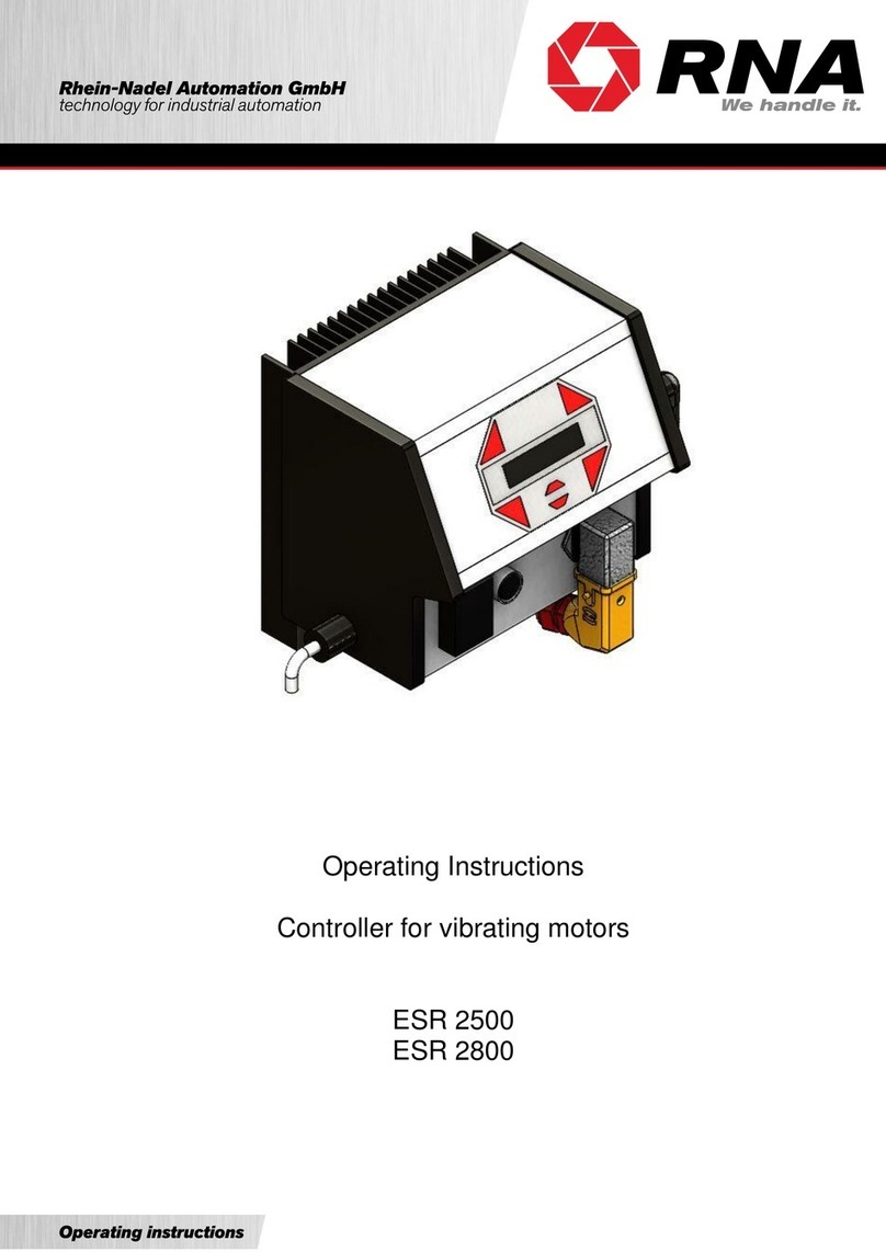
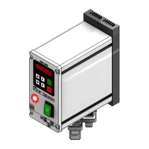
RNA EBC 10 User manual

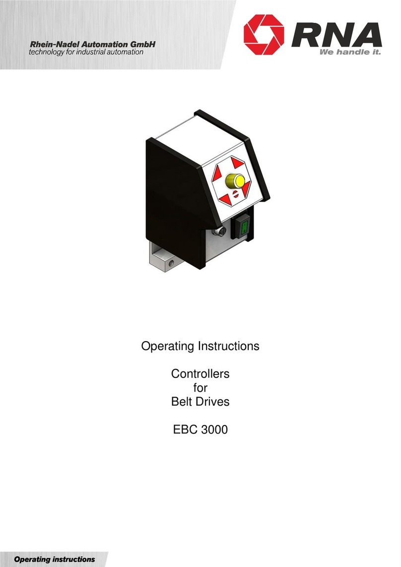
Operating Instructions
Controllers
for belt drives
EBC 10
EBC 10 S

Rhein - Nadel Automation GmbH - V/-BA-EBC10-DE –7 July 2021
Table of Contents
1. Technical data........................................................................................................................4
1.1. Functional description.....................................................................................................4
1.2. EC conformity .................................................................................................................4
1.3. Technical data.................................................................................................................4
2. Safety directives.....................................................................................................................4
3. Notes on start-up....................................................................................................................5
3.1. Setting the maximum speed ...........................................................................................6
3.2. Setting the minimum speed ............................................................................................6
3.3. Setting the maximum armature current...........................................................................6
3.4. Setting the acceleration and deceleration times .............................................................6
3.5. Setting the IxR compensation.........................................................................................6
3.6. Setting the control response...........................................................................................6
3.7. Enabling the function by external components ...............................................................6
3.8. Status output...................................................................................................................7
4. Connection diagram...............................................................................................................8
5. View and dimensions .............................................................................................................9
6. Connector pin assignment of the plug for EBC 10 S..............................................................9

Rhein - Nadel Automation GmbH - V/-BA-EBC10-DE –7 July 2021
Declaration of Conformity
According to the Low-Voltage Directive 2014/35/EU
and Electromagnetic Compatibility Directive 2014/30/EU
We hereby declare that the product meets the following requirements:
Low-Voltage Directive 2014/35/EC
Electromagnetic Compatibility Directive 2014/30/EU
Applied harmonised standards: DIN EN 60204 T1
EN 61439-1
Remarks:
Rhein-Nadel-Automation
---------------------------------
Managing Director
Jack Grevenstein

Rhein - Nadel Automation GmbH - V/-BA-EBC10-DE –7 July 2021
1. Technical data
1.1. Functional description
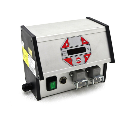
Controller for operation of variable-speed drives with a ratio of 1:4. The device supplies DC drives with permanent
excitation or shunt field from the mains. It controls the armature voltage. The mains cord and motor cable are
hardwired to the aluminium casing. The pilot devices are installed on the front panel. The integrated overcurrent
protection device faults out the system with a time delay. This condition is visually indicated on the front panel.
An internal motor current sensing feature (I x R compensation) provides sufficient constance of the set belt speed
in varying load conditions.
Minimum and maximum output voltage, Umin, Umax, acceleration and deceleration rates TUP, TDOWN, maximum mo-
tor current Imax and the influence of I x R compensation are all steplessly adjustable on the PCB. The drive can be
started and stopped at no-load via additional wiring with floating contact, or via a 24V DC signal. A floating transis-
tor output is provided for integration with other control system components.
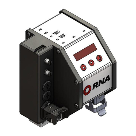
The EBC 10 S model controller has a plug-in connection for the motor cable.
1.2. EC conformity
The controller is compliant with following standards:
•EC Low-Voltage Directive 2014/35/EU
•Electromagnetic Compatibility Directive 2014/30/EU
The applicable standards are specified in the Declaration of Conformity.
1.3. Technical data
Mains supply
230 Volts 10%,
50/60 Hz
Armature voltage range
0...180 Volt DC
Max. armature current
3 Amps DC
Overcurrent release:
Operate delay
Restart
approx. 3 mm
Switching off supply
Status messages
NPN transistor 30V,
0.1A
Radio interference suppressed
acc. to EMC directive
Degree of protection
IP 54
Dimensions excluding fastening and pilot devices
90 x 175 x 117 (W x H x L)
Ambient temperature
0°-45°C
External enabling signal
Via floating contact or 24V DC signal (see above)
Status output
Optocoupler (max. 30V DC 100mA
2. Safety directives
Be sure to read and understand all safety information. Compliance with safety information will help to preserve val-
uable materials and equipment and prevent health issues.
Make sure that all persons working with this controller are familiar with all safety directives and observe them fully.
The device described here is a controller for operation of RNA belt drives. Observe the limits indicated in the tech-
nical specification.
Notice!
This hand symbol identifies useful tips for operation of the controller.
Attention!
This warning triangle indicates safety notices. Failure to comply with such warnings may result
in serious injury or even death!

Rhein - Nadel Automation GmbH - V/-BA-EBC10-DE –7 July 2021
Any work on electrical equipment of the machine/system shall be carried out exclusively by a
professional electrician, or by instructed persons working under the direction and supervision of
a professional electrician, according to electrotechnical rules!
Observe all safety and hazard notes and signs local to the equipment!
Inspect/check the electrical equipment of the machine/system periodically. Remedy defects
such as loose connections or damaged cables at once.
Prior to start-up make sure that the protective earth conductor is connected and in proper condition.
Make the PE conductor test with approved test devices only.
3. Notes on start-up
Make sure that following points are checked prior to making connection to power supply and switching
on the controller:
•Is the controller casing properly closed with all screws tightened?
•Are all plug hooks engaged / firmly screwed in place?
•Are all cables and glands in proper condition?
•Is operation for the INTENDED USE made sure?
•Does the supply voltage specified on the controller match the local supply system?
Only if you can clearly answer all the above questions with "Yes" should the controller be put into operation.
At delivery of a belt conveyor / hopper, all parameters on its controller have been factory-set. In case the controller
is replaced later on, take care to adjust these parameters to the existing drive. Figure 1 shows the locations of the
adjustment potentiometers
Anschluß
Störungsanzeige
1
2
3
11
4
5
6
7
10
8
9
12
13
14
15
Jumper
Freigabe extern
Imax
N max
I x R
PI
POTENTIOMETER
SOLLWERT
T-ab
T-auf
N min
Before starting any service works for which the controller has to be opened:
Switch off the device and pull the mains plug!
Be sure to observe all safety information. Danger to life!
Fig. 1: Locations of the adjustment potentiome-
ters on the printed circuit board.
Setting the minimum speed.
Operating time of deceleration rate
Range 0.1 - 8 sec.
Operating time of acceleration rate
Range 0.1 - 10 sec.
Control response of the voltage regulator.
Speed stabilization, compensation
of different conveyor loads.
Setting the maximum speed.
Setting the maximum armature current.
POTENTIOMETER
SETPOINT
Nmin
T-down
T-up
Pl
IXR
Nmax
Imax
Connection
Fault indication
Jumper External
enabling

Rhein - Nadel Automation GmbH - V/-BA-EBC10-DE –7 July 2021
3.1. Setting the maximum speed
Take care to make this setting with a tachometer, you will find the nominal r.p.m. on the rating plate of the motor.
The magnitude of the armature voltage is only a limited indicator for motor speed, since the motor speed also de-
pends on the field voltage which results from the magnitude of the local mains voltage. If it is not possible to meas-
ure the revolutions directly at the motor shaft, you can do so at the belt conveyor shaft. The speed reduction ratio
required for conversion is indicated on the gear unit.
3.2. Setting the minimum speed
The minimum speed must not be less than ¼ of the maximum speed, else sufficient cooling of the drive motor is no
longer guaranteed. The smallest permissible speed results from the maximum speed as shown on the rating plate
of the motor.
3.3. Setting the maximum armature current.
The correct setting of the armature current guarantees the full useful life of the drive and a minimum wear of the
carbon brushes. The measurement requires a measuring device for TRUE ROOT MEAN SQUARE (TRUE RMS)
measurements. Clip-on measuring instruments are usually not suited for this task. Measuring the current in the
mains supply line is permissible considering the field current.
The current limit is calculated as follows: Motor nominal current / form factor. You will find the nominal current of the
motor on the rating plate, the form factor normally is 1.4. For a motor nominal current of 3 amps, the current limit is
3 / 1.4 = 2.15 amps.
The form factor improves to factor 1.1, if a restrictor is integrated into the armature circuit. In this case the current
limit is 3 / 1.1 = 2.73 amps.
3.4. Setting the acceleration and deceleration times
The adjustable acceleration and deceleration rates permit the adjustment of the drive to the respective application.
Thus you can accelerate heavy loads to the desired conveyor speed desired without overloading the drive. Parts
that are fragile or tip over easily must be accelerated/decelerated in guided manner.
3.5. Setting the IxR compensation
Note that the standard drives are operated without tacho-generator. However the set speed is to remain as stable
as possible, therefore the controller is equipped with a compensation feature. With rising
armature current the setpoint automatically increases. The degree of this increase determines the setting of the
trimming potentiometer for I x R compensation. The optimum setting depends on the dynamics of the feeder. Take
care to adjust the trimming potentiometer until the drive keeps speed in varying load conditions. If the speed in-
creases at rising load, the influence of the compensation is too high and must be reduced.
3.6. Setting the control response
The position of the PI trimming potentiometer determines the intervention into dynamic feedback loop of the Pl
controller. If it is correctly adjusted and acceleration and deceleration times are set to a minimum, the drive steadily
runs up to, and remains at, the selected speed after power on or presence of the external enabling signal. If the in-
tervention is too big, the speed changes cyclically after run-up. If the intervention is too small, the drive overshoots,
i.e. after starting it first accelerates to a higher speed than selected and only then picks up the right speed.
3.7. Enabling the function by external components
In the standard setting of the controller the drive starts as soon as the power supply is switched on. If you want the
controller to work in Start - Stop operation without disconnecting it from the mains supply, open the controller in ac-
cordance with the following description while observing the safety information above. Replace the blanking plug in
the side of the casing by a size PG 9 strain-relieved cable gland to feed through the cable for the enabling signal.
There are two ways of enabling:
Enabling via a contact
This simple inexpensive solution means that a contact enables the controller by closing and the drive starts work-
ing. The connection is made at terminals 10 and 11, after removing the factory-fitted jumper. Be sure to consider
the following points:
•Mains voltage is present at this connection! Take care to observe cable type and colour, isolation instructions
and that the contact of course has to be floating.
•Be sure that the cable is shielded. The shield must be connected to the protective earth conductor on the con-
troller side.
•The cable length must not exceed 5 meters.
•Avoid routing this cable in the immediate vicinity of high-energy switching devices or strong interference fields.

Rhein - Nadel Automation GmbH - V/-BA-EBC10-DE –7 July 2021
Enabling via voltage signal.
Terminals 10 and 11 must be jumpered, be sure to remove the ENABLE jumber from the board. Use terminals 12
and 13 to connect the enabling signal. The drive starts as soon as a signal between 10 and 30 volt of direct current
is available with the correct polarity. The input is protected against polarity reversal. Use an optocoupler in the con-
troller to make the input floating, permitting the installation of non-shielded cables of almost any length. Here too,
take care to avoid high-energy interferences.
3.8. Status output
The status output provides a floating transistor circuit which is active whenever the controller is connected to mains
supply and switched on and the drive is working. The transistor is NPN-doped and switches voltages up to 30 volt
DC with a maximum current of 100 mA. To ensure the most universal use possible, we have decided against in-
stalling any suppressor circuit. The user has to exercise due diligence here.

Rhein - Nadel Automation GmbH - V/-BA-EBC10-DE –7 July 2021
4. Connection diagram
Mains connection 230V, 50/60Hz
Imax Nmax IxR Pl T-up T-down Nmin
Armature current max. 3A
Jumper
Internal
enabling
External enabling
Contact 24 VDC
Status signal
active
Belt drive
To reverse sense of rotation ex-
change connections J and K on
the motor terminal board.
XSI connector only for
EBS105
Contact
Contact

Rhein - Nadel Automation GmbH - V/-BA-EBC10-DE –7 July 2021
5. View and dimensions
6. Connector pin assignment of the plug for EBC 10 S
Plug pin Line Motor connection
1 No. 1 A1
2 No. 2 A2
3 No. 3 F1
4 No. 4 F2
5 N.C.
6 N.C.
PE green/yellow PE

RNA Group
Headquarters
Manufacturing and Sales
Rhein-Nadel Automation GmbH
Reichsweg 19-23
D-52068 Aachen
Phone: +49 (0) 241-5109-0
Fax: +49 (0) 241-5109-219
www.RNA.de
Further RNA group companies:
Manufacturing and Sales
Focus: Pharmaceutical Industry
PSA Zuführtechnik GmbH
Dr.-Jakob-Berlinger-Weg 1
D-74523 Schwäbisch Hall
Phone: +49 (0) 791 9460098-0
Fax: +49 (0) 791 9460098-29
www.psa-zt.de
Manufacturing and Sales
RNA Automation Ltd.
Unit C
Castle Bromwich Business Park
Tameside Drive
Birmingham B35 7AG
United Kingdom
Phone: +44 (0) 121 749-2566
Fax: +44 (0) 121 749-6217
E-mail: RNA@RNA-uk.com
www.rnaautomation.com
Manufacturing and Sales
HSH Handling Systems AG
Wangenstr. 96
CH-3360 Herzogenbuchsee
Switzerland
Phone: +41 (0) 62 956 10-00
Fax: +41 (0) 62 956 10-10
E-mail: info@handling-systems.ch
www.handling-systems.ch
Manufacturing and Sales
Pol. Ind. Famades c/Energia 23
E-08940 Cornella de Llobregat (Barcelona)
Spain
Phone: +34 (0)93 377-7300
Fax: +34 (0)93 377-6752
E-mail: info@vibrant-RNA.com
www.vibrant-RNA.com
www.vibrant.es
Vertrieb
Agnes-Pockels-Bogen 1
80992 München
Phone: +49 1515 / 99 28 255
E-mail: kontakt@rnadigital.de
www.designforfeeding.com
Further manufacturing sites
of the RNA Group
Manufacturing
Lüdenscheid branch
Rhein-Nadel Automation GmbH
Nottebohmstraße 57
D-58511 Lüdenscheid
Phone: +49 (0) 2351 41744
Fax: +49 (0) 2351 45582
E-mail: werk.luedenscheid@RNA.de
Manufacturing
Ergolding branch
Rhein-Nadel Automation GmbH
Ahornstraße 122
D-84030 Ergolding
Phone: +49 (0) 871 72812
Fax: +49 (0) 871 77131
E-mail: werk.ergolding@RNA.de
Manufacturing
Remchingen branch
Rhein-Nadel Automation GmbH
Im Hölderle 3
D-75196 Remchingen-Wilferdingen
Phone: +49 (0) 7232 - 7355 558
E-mail: werk.remchingen@RNA.de
This manual suits for next models
1
Table of contents
Other RNA Controllers manuals
Popular Controllers manuals by other brands

Smartgen
Smartgen HAT530 user manual

HomeMatic
HomeMatic HM-LC-Sw1-DR Installation and operating manual

VERDER
VERDER Carbolite Gero Chessell 6100A Installation, operation and maintenance instructions

Dakota Digital
Dakota Digital PAC-2700 manual

Immergas
Immergas CARV2 Instruction and warning book

Dometic
Dometic GP-MPPT-60/10 user manual