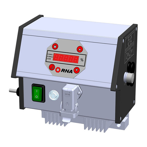
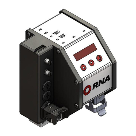
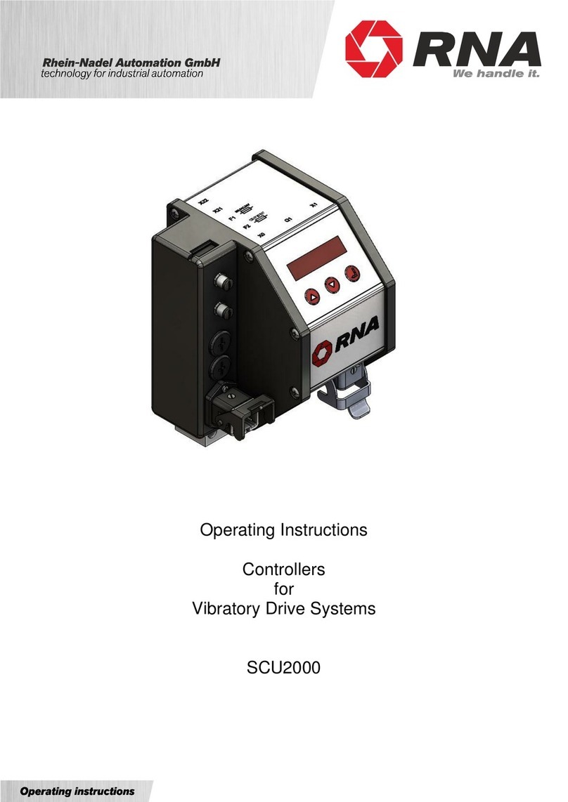
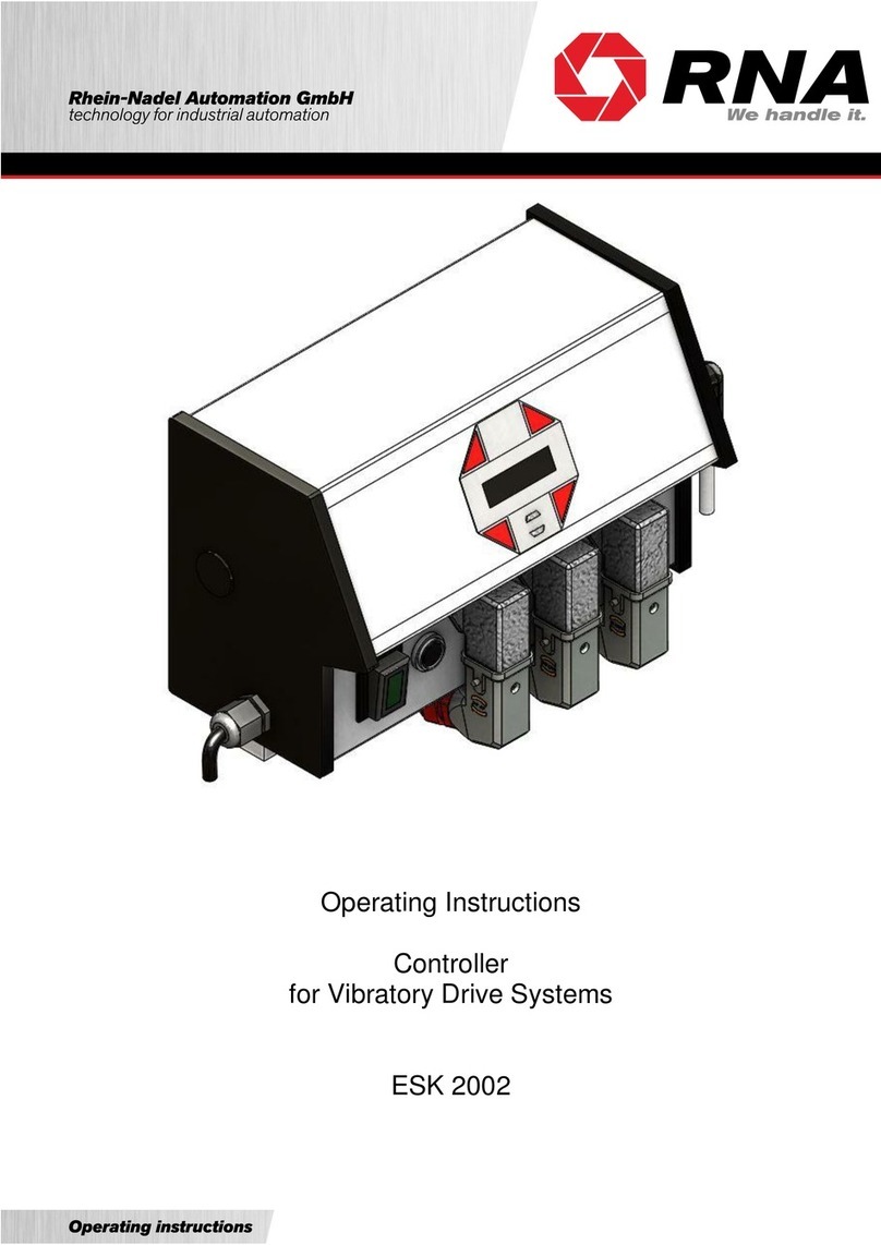
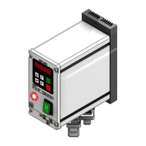
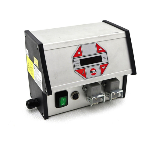
RNA ESK 2000 User manual

Operating Instructions
Controllers
for
Vibratory Drive Systems
ESK 2000

Rhein-Nadel Automation GmbH 2
VT-BA-ESK2000_EN_2023.docx
Table of Contents
1. About this document ..............................................................................................................4
2. Safety information..................................................................................................................4
2.1. Design of safety directives ...............................................................................................4
2.2. Fundamental safety directives..........................................................................................4
2.3. Personnel.........................................................................................................................4
2.4. Intended use ....................................................................................................................5
2.5. Residual hazards..............................................................................................................5
2.5.1. Device ........................................................................................................................5
2.5.2. Protection of the drive system....................................................................................5
2.5.3. Degree of protection - Protection of persons and equipment .....................................5
3. Product information................................................................................................................6
3.1. Characteristic features .....................................................................................................6
3.2. EC conformity...................................................................................................................6
3.3. Technical data..................................................................................................................6
3.4. Accessories......................................................................................................................7
4. Notes on start-up....................................................................................................................7
4.1. Modes of operation...........................................................................................................7
4.2. Automatic mode change...................................................................................................8
4.3. Sensor inputs and sensor linkages...................................................................................8
4.4. Sensor connection............................................................................................................9
4.5. Status outputs and relays...............................................................................................10
5. Operation .............................................................................................................................10
5.1. General ..........................................................................................................................10
5.2. Starting-up the controller................................................................................................11
5.3. Main menu / Setpoint entry and display .........................................................................12
5.4. Description of individual codes for controller programming............................................13
5.5. Application-specific changes to default settings.............................................................14
5.5.1. Code C001 feed rate output.....................................................................................14
5.5.2. Code C003 Seal setpoint..........................................................................................14
5.5.3. Code C004 sensor input 1 and code C005 sensor input 2.......................................15
5.5.4. Code C006 Sensor linkage.......................................................................................16
5.5.5. Code C008 cycle monitoring ....................................................................................18
5.5.6. Code C009 Show status...........................................................................................19
5.5.7. Code C200 Inhibiting all code entries.......................................................................19
5.5.8. Code C100 Setting the feed rate by external voltage input. .....................................20
5.5.9. Code C143 Saving parameters................................................................................20
5.5.10. Code C210 Retrieving parameters...........................................................................21
6. Error message......................................................................................................................21
7. Dimensioned drawing...........................................................................................................22
8. Connection diagram.............................................................................................................23

Rhein-Nadel Automation GmbH 3
VT-BA-ESK2000_EN_2023.docx
Declaration of Conformity
According to the Low-Voltage Directive 2014/35/EU
and Electromagnetic Compatibility Directive 2014/30/EU
We hereby declare that the product meets the following requirements:
Low-Voltage Directive 2014/35/EC
Electromagnetic Compatibility Directive 2014/30/EU
Applied harmonised standards: DIN EN 60204 T1
EN 61439-1
Note:
Rhein-Nadel-Automation
---------------------------------
Managing Director
Jack Grevenstein

Rhein-Nadel Automation GmbH 4
VT-BA-ESK2000_EN_2023.docx
Document description:
This document provides assistance in choosing your product. You will also find information on mechanical
and electrical installation, operation, product extensions and accessories.
Non-observance may cause trouble with the product or the environment, reduce the product lifetime or lead
to other damage.
Non-observance of the following fundamental safety measures and directives may lead to severe injury and
damage to property!
Meeting the requirements given in the related documentation is a precondition for safe and trouble-free op-
eration and for achieving the product properties specified. Further additional safety directives in the other
sections must be observed as well.
Only qualified professionals are allowed to work on or with the product. IEC 60364 or CENELEC HD 384
define the qualification of these persons:
•They are familiar with set-up, installation, commissioning and operation of the product.
•They possess the qualification required for performance of their work.
•They know all regulations for the prevention of accidents, directives and laws applicable to set-up,
installation and commissioning on site, and they are able to apply the same.
•They have knowledge and skills of First Aid.
1. About this document
Attention
Read this document carefully and observe the safety directives before commencing any work.
2. Safety information
2.1. Design of safety directives
Notice
This notice identifies useful tips for use of the controller.
Attention!
This symbol identifies hazardous situations.
Non-observance of such warnings may cause irreversible injury or even death!
2.2. Fundamental safety directives
2.3. Personnel
Attention!
Any work on electrical equipment of the machine/system shall be carried out exclusively by a
professional electrician, or by instructed persons working under the direction and supervision of a
professional electrician, according to electrotechnical rules.

Rhein-Nadel Automation GmbH 5
VT-BA-ESK2000_EN_2023.docx
Please observe the following directives for intended use of the controllers:
•The devices herein described must only be stored, fitted and operated under the conditions
specified in this documentation.
•Here you are not concerned with domestic devices! They are solely intended to be used as com-
ponents for commercial or professional applications pursuant to EN 61000−3−2.
•They satisfy the protection requirements of 2014/35/EU: Low Voltage Directive.
•They do not constitute a machine as defined by 2006/42/EU: Machinery Directive.
•A machine comprising the product must not be commissioned or put into operation for the in-
tended use until it has been declared to be in conformity with the EC Directive 2006/42/EU: Ma-
chinery Directive; Observe EN 60204−1.
•Commissioning or starting operation for the intended use is only permitted in compliance with the
EMC Directive 2014/30/EU.
•Use of the product in living areas may lead to EMC disturbance. The user is responsible for tak-
ing interference suppression measures.
•They are optimised for operation of RNA bowl feeders and linear feeders. Observe the limits in-
dicated in the technical specification.
Residual hazards may remain even if all directives have been observed and protective measures taken.
Such residual hazards must be considered by the user in the risk assessment of his machine/equipment.
Non-observance may lead to severe injury and damage to property!
Pay attention to the warning signs fitted to the device!
Symbol
Description
Hazardous voltage:
Prior to commencing any work on the product check for absence of voltage on all power connections.
Leakage current:
Make fixed installation and PE connection according to EN 60204−1!
Certain device parameter settings may cause overheating of the connected drive magnet, e.g., due to pro-
longed operation with an incorrect voltage setting.
•All specifications relate to installed condition ready for operation.
•All slots not used must be closed by protection caps or dummy plugs in order not to reduce the pro-
tection against accidental contact.
2.4. Intended use
Attention!
•Prior to start-up make sure that the protective earth conductor is connected and in proper
condition. Make the PE conductor test with approved test devices only.
•Never start up despite detected damage.
•Do not make any technical modifications to the device, except as described in this docu-
ment.
•Never start up in an incompletely installed state.
•Never operate the device without the required guards in place.
•Connect, disconnect or change any electrical connections only in the absence of voltage.
2.5. Residual hazards
2.5.1. Device
2.5.2. Protection of the drive system
2.5.3. Degree of protection - Protection of persons and equipment

Rhein-Nadel Automation GmbH 6
VT-BA-ESK2000_EN_2023.docx
The compact controller is designed for operation of a vibratory or belt feeder drive system.
The unit offers the following characteristic features:
- One feed rate output: Bowl feeder, linear feeder max. 10A, variable
or AC capacitor motor max. 3A, not variable
- Two sensor amplifiers with independently adjustable timers (On/Off delay).
- External enabling input, 24 VDC
- Two relay outputs and two optocouplers for status messages and other links.
- Membrane keypad for setting and changing the operating parameters in the set-up menus.
- Plug-type connections for
- Vibratory or belt feeder drive
- Sensors
- Communication with higher-level controller
- Bipolar main disconnect switch.
The controller is compliant with the following standards:
EC EMC Directive 2014/35/EU
EC Low-Voltage Directive 2014/30/EU
Applied harmonised standards:
DIN EN 60204, part 1
EN 61439-1
The controller is also available in a UL/CSA compliant version.
Mains voltage:
230 V AC, 50/60 Hz, +20 / -15%
115 V AC, 50/60 Hz, +10 / -10%
Output voltage:
0 ... 208Veff; (230VAC in motor mode) at 230V supply voltage;
0 ... 98Veff; (115VAC in motor mode) at 115V supply voltage
Load current:
10 Aeff., in motor mode 3A
Minimum load current:
80 mA
Internal fuse:
F1 = 10A med.time lag
Control-circuit fuse:
2A med.time lag
Soft start delay, soft stop delay:
0 ... 5 sec. separately selectable
External setpoint:
0 ... 10V DC
Sensor inputs:
2
Enabling input:
24V DC (10-24VDC)
Sensor supply:
24V DC, max. 60 mA (per sensor input)
Sensor ON delay:
0 ... 60 sec. separately adjustable
Sensor OFF delay:
0 ... 60 sec. separately adjustable
Outputs:
2 relays (max. 6A 250VAC)
2 floating changeover contacts
2 normally-open contacts carrying supply voltage
2 status outputs (optocoupler):
2 optocouplers, max. 30VDC 10mA,
Ambient temperature:
0 ... 50° C
Cooling:
free convection
Mounting:
vibration-free
Degree of protection:
IP54
Leakage current
Less than 2mA
Power loss
max. 30W
3. Product information
3.1. Characteristic features
3.2. EC conformity
3.3. Technical data

Rhein-Nadel Automation GmbH 7
VT-BA-ESK2000_EN_2023.docx
Tag
Designation
Type
RNA part No.:
XS1
Load connector
5-pin
31002323 (100Hz drive)
XS1
Load connector
5-pin
31002322 (50Hz drive)
XS3
Male connector
5-pole, straight
35051144
XS3
Male connector
5-pole, right-angled
35002546
XS4
Female connector
7-pole, straight
35051153
XS4
Female connector
7-pole, right-angled
35002545
For XS3
Y adapter
39905940
Attention:
Make sure that following points are checked prior to making connection to power supply and
switching on the controller:
•Is the controller casing properly closed with all screws tightened?
•Are all plug hooks engaged / firmly screwed in place?
•Are all cables and glands in proper condition?
•Is operation for the INTENDED USE made sure?
•Does the supply voltage specified on the controller match the local supply system?
•Does the supply frequency specified on the vibratory drive match the local supply sys-
tem?
•Is the correct mode set on the controller? (See description under "Modes of Operation")
•Is sufficient cooling of the controller ensured?
•Is the controller mounting vibration-free?
Only if you can clearly answer all the above questions with "Yes" should the controller be put into operation.
Attention:
Set the controller to minimum output before switching-on for commissioning or start-up after re-
pairs or replacement of controllers/vibratory drives. Then check for proper operation while the
output is increased.
RNA vibratory drive systems employ mechanical spring vibrators which are set to a vibrating frequency
near the mains frequency or near double mains frequency depending on weight and/or size.
This is why two modes of operation are possible:
Mode 1: Asymmetric half-wave mode:
The vibrating drive operates at mains frequency.
Mode 2: Symmetric full-wave mode:
The vibrating drive operates at double mains frequency.
To assist the operator the cable glands on the drive connector are colour-coded.
Mode 1: Black
Mode 2: grey
In terms of the vibrating frequency this means:
Mains frequency 50 Hz
Mains frequency 60 Hz
Cable gland colour
Mode 1
Half-wave mode
Vibrating frequency
50 Hz ≙3000 min-1
Vibrating frequency
60 Hz ≙3600 min-1
Black
Mode 2
Full-wave mode
Vibrating frequency
100 Hz ≙6000 min-1
Vibrating frequency
120 Hz ≙7200 min-1
grey
3.4. Accessories
4. Notes on start-up
4.1. Modes of operation

Rhein-Nadel Automation GmbH 8
VT-BA-ESK2000_EN_2023.docx
Vibratory drive systems by RNA do not require the operator to take care of selecting the right operating mode.
The operating mode is determined by a code in the RNA vibrating drive connector. A wire jumper from pin 3
to 4 in the connector switches the controller to mode 2: 100 or 120 Hz. In the absence of this wire jumper the
controller operates in mode 1: 50 or 60 Hz.
The RNA vibratory drive systems come with the right code in the connector.
Mode changes are made only and exclusively via the coding in the vibrating drive connector.
(Where frequency controllers with selectable output frequency are used, an EMC metal gland and a shielded
cable are provided.)
Two sensor inputs are integrated into the controller. They enable you to implement accumulation checks,
level checks, cycle monitoring and other monitoring tasks. The following basic assignments are made: Sen-
sor input 1 acts on channel 1, unless otherwise programmed in menu C006. Sensor input 2 is provided for
additional functions, see sensor linkage. The sensor inputs can be evaluated only if they are activated in
codes C004, C005. For sensor connection (connector XS3) please refer to the connection diagram.
4.2. Automatic mode change
4.3. Sensor inputs and sensor linkages
M20 gland
Black: 50/60Hz vibrating frequency
Grey: 100/120Hz vibrating frequency
(EMC metal gland if frequency controllers are
used.)

Rhein-Nadel Automation GmbH 9
VT-BA-ESK2000_EN_2023.docx
The controller has two sensor inputs which can be used for accumulation checking and/or level monitoring
purposes. You can connect sensors of type NPN or PNP.
4.4. Sensor connection
10K if
req‘d
Proximity switch,
general,
NPN output
Proximity switch,
general,
PNP output
PNP switching sensors may require a 10K
resistor between sensor output and 0V.
Floating contact
EGF40
(optical sensor w/o
amplifier)
Sensor 2,
Proximity switch,
general,
NPN output
Y adapter
Y adapter
10K
if req‘d
Sensor 1
Proximity switch,
general,
PNP output
EGF40
(optical sensor w/o
amplifier)
contact
Connection of 2 sensors via Y adapter

Rhein-Nadel Automation GmbH 10
VT-BA-ESK2000_EN_2023.docx
The status outputs are used for remote diagnostics of the controller status or of the links of several controllers
with one another. They are designed as freely available NPN-doped transistor circuits and they are floating.
With the status output READY the transistor circuit is switched through whenever the controller is connected
to power supply and switched on by its power switch closed.
The status output ACTIVE requires the same conditions for switching-through as "READY". In addition, chan-
nel 1 must be operating actively, the transistor blocks in case of ACCUMULATION, OFF or STOP.
The status outputs and inputs as well as the external enabling input are to be wired via plug connector XS4.
The two relays have different functions. K1 operates as a status relay parallel to the ACTIVE status output.
K2 serves either for a blowing air switch-off delay (4 sec.) or for cycle monitoring of one of the two sensor
channels.
Connections and cable entry are located on the right side panel of the controller. The terminal block is located
behind the controller side panel.
Controller plug connections
Main disconnect switch
Double-pole isolation of the controller from power supply
XS 3
Connector for sensors
Channel 1 (XS1)
Connector for bowl feeder or linear feeder or motor (<10A)
XS 4
Connector for optocoupler outputs and external enabling input
4.5. Status outputs and relays
5. Operation
5.1. General
Cursor
down
Enter
On / Off
Cursor up
Main disconnect
switch
Channel 1
XS 3
XS 4

Rhein-Nadel Automation GmbH 11
VT-BA-ESK2000_EN_2023.docx
The controller display (membrane keypad)
On / Off
Pressing this button switches off all connected devices. The display shows "OFF". The
controller remains ready for operation.
Cursor up and cursor down
Use these buttons to scroll through the controller menu or set the parameters.
Enter
Press this button to acknowledge the parameters entered with the cursor.
Decimal point in the display
The decimal point is not blinking. You cannot make any entry.
The decimal point is blinking, an entry can be made.
To start up the controller, close the main disconnect switch. The main menu appears on the display show-
ing the last setpoint entered (feed rate of the vibratory feeder or linear feeder).
KANAL l
KANAL 2
CODE
Alternatively, the following may appear on the display depending on the switching status of the device:
KANAL l
KANAL 2
CODE
External enabling signal has been activated but it is withdrawn from the device at the moment.
(medium priority)
KANAL l
KANAL 2
CODE
Device has been switched off by operating the top left button of the membrane keypad, inhibiting
all functions. (high priority)
KANAL l
KANAL 2
CODE
The accumulation monitoring sensor is operated, switching off the vibratory drive. (low priority)
5.2. Starting-up the controller

Rhein-Nadel Automation GmbH 12
VT-BA-ESK2000_EN_2023.docx
Display of setpoint or feed rate
(vibratory feeder)
Alternatively: STOP, OFF or AC-
CUMULATION (see above)
No entry possible
,
Entry of the codes to change or
execute the required settings.
Enter code.
Description of codes
see under 4.4.
Setpoint entry for channel 1
(bowl feeder or linear feeder)
Entry in %; return to
display mode for
saving
Use the cursor buttons (UP/ DOWN) to scroll through these three basic screens of the main menu. In each
individual item of the main menu you can press ENTER to activate this item for setting or changing. Upon
pressing of the ENTER button the decimal point starts blinking. Now you can make changes using the cursor
buttons (UP/DOWN). Press ENTER again to acknowledge the entries made. The decimal point is no longer
blinking. Using the cursor buttons you can continue scrolling in the menu. Same procedure analogously ap-
plies to the code menus described below.
KANAL l
KANAL 2
CODE
KANAL l
KANAL 2
CODE
KANAL l
KANAL 2
CODE
5.3. Main menu / Setpoint entry and display

Rhein-Nadel Automation GmbH 13
VT-BA-ESK2000_EN_2023.docx
All the following display screens show the default setting. If the actual indication on the controller differs from
what is shown here, the default setting has been changed in individual codes to suit a specific application.
Settings for channel 1
In this sub-menu you can set or limit the following functions for channel 1:
- Vibrating amplitude
- External enabling, signal direction of external enabling input
- Soft start and stop delay
- Selection of vibratory or belt feeder drive
Sealing a setpoint
In this sub-menu you can lock the setpoints (vibrating amplitude) of the main menu. It
is no longer possible to change the setpoints for channel 1 in the main menu. This
avoids accidental changes to performance parameters. You can only make any
changes now through code C001.
Setting the sensor input 1
This is the sub-menu for activation of sensor input 1. In addition you can set the fol-
lowing functions:
- Invert input signal direction
- Start delay
- Stop delay
Setting the sensor input 2
This is the sub-menu for activation of sensor input 2. In addition you can set the fol-
lowing functions:
- Invert input signal direction
- Start delay
- Stop delay
Choosing the sensor links
In this sub-menu you can link the sensors activated by codes C004 and C005 with
one another.
Setting the cycle watchdog
Here you can set which sensor input is to be monitored and how the controller is to
react to an error.
Show status
This sub-menu serves for checking of the set vibrating frequency and of the sensor
inputs.
Calling-up the software version
Definition: 411. 57. 10. 23.11.99
Date
Version No.
Device type
Internal No.
Device type:
59 = ESK 2001
58 = ESG 2001
57 = ESK 2000
56 = ESG 2000
Setting the feed rate by external voltage input 0-10V or potentiometer
Saving parameters
You can save the (application-specific) settings previously made in various sub-
menus under code 143.
Inhibiting all setting functions
With the aid of this code you can disable all input facilities of the controller. It is no
longer possible to change any values. The only way now to enable the menu again is
through this code.
Retrieving parameters
Inn this sub-menu you can return the controller to the default settings. You can also
return to application-specific settings, if previously saved.
KANAL l
KANAL 2
CODE
KANAL l
KANAL 2
CODE
KANAL l
KANAL 2
CODE
KANAL l
KANAL 2
CODE
KANAL l
KANAL 2
CODE
KANAL l
KANAL 2
CODE
KANAL l
KANAL 2
CODE
KANAL l
KANAL 2
CODE
KANAL l
KANAL 2
CODE
KANAL l
KANAL 2
CODE
KANAL l
KANAL 2
CODE
KANAL l
KANAL 2
CODE
5.4. Description of individual codes for controller programming.

Rhein-Nadel Automation GmbH 14
VT-BA-ESK2000_EN_2023.docx
Objective: Setting and limiting the vibration amplitude, external enabling, soft start delay and soft stop de-
lay.
Select code
KANAL l
KANAL 2
CODE
Set code
Code C001
KANAL l
KANAL 2
CODE
Set vibrating amplitude
KANAL l
KANAL 2
CODE
0 - 100 %
Limit vibrating amplitude
KANAL l
KANAL 2
CODE
50 - 100 % (*)
External enabling signal
KANAL l
KANAL 2
CODE
I = active
0 = not active
External enabling signal
direction
KANAL l
KANAL 2
CODE
I = Start = 24V DC
0 = Stop = 24V DC
Soft start time
KANAL l
KANAL 2
CODE
0 - 5 sec.
Soft stop time
KANAL l
KANAL 2
CODE
0 - 5 sec.
Select vibratory drive or
belt drive
KANAL l
KANAL 2
CODE
0 = vibratory drive
1 = belt drive
Return
KANAL l
KANAL 2
CODE
Save and return to
main menu
(*) For RNA feeders with 200 V magnets = 90 %
Objective: Sealing-in the setpoints in the main menu. A direct change of the values is no longer possible.
You can only make changes now through code C001.
Select code
KANAL l
KANAL 2
CODE
Set code
Code C003
Setpoint (vibrating ampli-
tude)
1 = adjustable
0 = input inhibited
Return
Save and return to
main menu
KANAL l
KANAL 2
CODE
KANAL l
KANAL 2
CODE
KANAL l
KANAL 2
CODE
5.5. Application-specific changes to default settings
5.5.1. Code C001 feed rate output
5.5.2. Code C003 Seal setpoint

Rhein-Nadel Automation GmbH 15
VT-BA-ESK2000_EN_2023.docx
Objective: Activating and setting the sensor inputs
Select code
Set code
Code C004
Sensor 1 input
I = active
0 = not active
Invert input signal
direction
I = Start = 24V DC
0 = Stop = 24V DC
Delay of sensor status
CLEAR, Start delay
0 - 60 sec.
Delay of sensor status
OPERATED, Stop delay
0 - 60 sec.
Return
Save and return to
main menu
Same applies analogously to code C005 (sensor input 2).
KANAL l
KANAL 2
CODE
KANAL l
KANAL 2
CODE
KANAL l
KANAL 2
CODE
KANAL l
KANAL 2
CODE
KANAL l
KANAL 2
CODE
KANAL l
KANAL 2
CODE
KANAL l
KANAL 2
CODE
5.5.3. Code C004 sensor input 1 and code C005 sensor input 2

Rhein-Nadel Automation GmbH 16
VT-BA-ESK2000_EN_2023.docx
KANAL l
KANAL 2
CODE
Objective: Linking of the two previously activated sensor inputs.
Select code
Set code
Code C006
KANAL l
KANAL 2
CODE
Logic with blowing-off
the exit tracks
KANAL l
KANAL 2
CODE
I = active
0 = not active
AND logic without blowing
off the exit tracks
(Version No. 10 and higher)
I = active
0 = not active
OR logic
KANAL l
KANAL 2
CODE
I = active
0 = not active
Min/Max logic
KANAL l
KANAL 2
CODE
I = active
0 = not active
AND / S2 logic
(Version No. 10 and higher)
KANAL l
KANAL 2
CODE
I = active
0 = not active
Level check with external
controller
KANAL l
KANAL 2
CODE
I = active
0 = not active
Level check with indicator
light
KANAL l
KANAL 2
CODE
I = active
0 = not active
Individual link
KANAL l
KANAL 2
CODE
I = active
0 = not active
Return
KANAL l
KANAL 2
CODE
Save and return to
main menu
Brief description of individual links
AND logic of the two sensor inputs with blowing-off the exit tracks.
Example:
Application:
Twin-track feeders with accumulation checker.
Solution:
Track 1 (sensor 1) full = Blow-off track 1 (relay K1)
Track 2 still clear
Track 2 (sensor 2) full = Blow-off track 2 (relay K2)
Track 1 still clear
Track 1 + Track 2 full = Bowl feeder (channel 1) Stop about 4 sec. later blowing
air stop
KANAL l
KANAL 2
CODE
5.5.4. Code C006 Sensor linkage
You can activate only one of the eight sensor links.

Rhein-Nadel Automation GmbH 17
VT-BA-ESK2000_EN_2023.docx
AND logic of the two sensor inputs without blowing-off the exit track. Bowl feeder (channel 1)
stops when both sensors are operated. Orienting air can be switched off with delay (4 sec.) via
relay K2.
OR logic of the two sensor inputs.
Bowl feeder (channel 1) stops when one of the two sensors is operated. Orienting air can be
switched off with delay (4 sec.) via relay K2.
Min/Max logic of the two sensor inputs.
The bowl feeder stops when both sensors are operated. The vibratory feeder (channel 1) will re-
start only after both sensors are cleared again.
Relay K1 operates on stopping of bowl feeder. Relay K2 operates 4 sec. later (stopping the
blowing air)
AND / S2 logic
Bowl feeder (channel 1) stops when both sensors are operated. It starts when sensor 2 is
cleared again. Orienting air can be switched off with delay (4 sec.) via relay K2.
Level check for hoppers with external hopper control
Sensor 2 operates relay K1 following the delay period entered (C005).
When sensor 1 is operated, relay K1 drops out (hopper interlock).
Application:
Sensor 1 = accumulation check;
Sensor 2 = level check;
Relay K1 = hopper control
Level check with indicator light
Sensor 2 operates relay K1 following the delay period entered (C005).
Application:
Sensor 2 is used as a level checker (e.g., LC-N 24V DC).
Relay K1 operates an indicator light: Bowl feeder or linear feeder empty.

Rhein-Nadel Automation GmbH 18
VT-BA-ESK2000_EN_2023.docx
Objective: Monitoring of sensors 1 (accumulation check) and/or 2.
When activating the cycle monitoring function, the "AND, SOL" links in code C006 must not be activated!!!
Select code
KANAL l
KANAL 2
CODE
Set code
Code C008
KANAL l
KANAL 2
CODE
Sensor input 1 is moni-
tored
KANAL l
KANAL 2
CODE
I = active
0 = not active
Sensor input 2 is moni-
tored
KANAL l
KANAL 2
CODE
I = active
0 = not active
Monitoring depending on
channel 1
KANAL l
KANAL 2
CODE
I = active
0 = not active
Time till alarm comes up
KANAL l
KANAL 2
CODE
3 - 240 sec.
Switching off channel 1
KANAL l
KANAL 2
CODE
I = see below
0 = see below
Switch
KANAL l
KANAL 2
CODE
I = Alarm on relay
K1
0 = Alarm on relay
Return
KANAL l
KANAL 2
CODE
Save and return to
main menu
5.5.5. Code C008 cycle monitoring
The cycle watchdog monitors the CLEAR sensor status. The time (A 180) sets the maximum du-
ration for which a sensor is allowed to be clear before an alarm message is generated.
In case of an alarm the relay K2 is clocked on and off. Reset takes place automatically when the
sensor is operated again.
If OUT = 1 the alarm operates relay K2 (indicator light: Error) and also stops the bowl feeder or
linear feeder. An ERROR message appears on the panel display.
Use the bottom right cursor button for reset.
If OUT = 0 the alarm only operates relay K2 (indicator light: Error).
Reset takes place automatically when sensor 1 is operated.
If A.I. = 1 relay K1 is clocked on and off in response to the alarm (switching from relay K2 to re-
lay K1).

Rhein-Nadel Automation GmbH 19
VT-BA-ESK2000_EN_2023.docx
Objective: Checking of the set vibrating frequency and of the sensor inputs.
Select code
KANAL l
KANAL 2
CODE
Set code
Code C009
External enabling signal
Channel 1
I = active
0 = not active
Channel 1 vibrating
frequency
I = 50 Hz
0 = 100 Hz
Signal at sensor input 1
I = active
0 = not active
Signal at sensor input 2
I = active
0 = not active
Return
Save and return to
main menu
Objective: An (accidental) change of the set values by the user is not possible any more.
Select code
KANAL l
KANAL 2
CODE
Set code
Code C200
KANAL l
KANAL 2
CODE
Inhibiting the setting
functions
KANAL l
KANAL 2
CODE
I = enable
0 = disable
Return
KANAL l
KANAL 2
CODE
Save and return to
main menu
KANAL l
KANAL 2
CODE
KANAL l
KANAL 2
CODE
KANAL l
KANAL 2
CODE
KANAL l
KANAL 2
CODE
KANAL l
KANAL 2
CODE
KANAL l
KANAL 2
CODE
5.5.6. Code C009 Show status
Under menu item HA = half wave you can check whether the correct operating mode
(50/60Hz or 100/120Hz) is set.
5.5.7. Code C200 Inhibiting all code entries
Only code C200 is accepted!!!
You can change the setpoints for channels 1 and 2 in the main menu (see under 4.3).

Rhein-Nadel Automation GmbH 20
VT-BA-ESK2000_EN_2023.docx
Objective: Setpoint change by external voltage
Select code
KANAL l
KANAL 2
CODE
Set code
Code C100
KANAL l
KANAL 2
CODE
External voltage applica-
tion to channel 1
KANAL l
KANAL 2
CODE
I = active
0 = not active
Return
KANAL l
KANAL 2
CODE
Save and return to
main menu
Objective: Saving of application-specific parameters
Select code
KANAL l
KANAL 2
CODE
Set code
Code C143
KANAL l
KANAL 2
CODE
Save
KANAL l
KANAL 2
CODE
KANAL l
KANAL 2
CODE
Return
KANAL l
KANAL 2
CODE
Save and return to
main menu
5.5.8. Code C100 Setting the feed rate by external voltage input.
If external voltage application is activated the last digital feed rate set (%) constitutes the mini-
mum feed rate for 0 volt. Set the maximum feed rate for 10 volt by the P parameter in C001.
Connect the external voltage to terminals 31, 32 and 33 in the controller.
You find the terminals behind the right-hand side panel.
Terminal 31 = +10V
Terminal 32 = E
Terminal 33 = 0V
Attention!
Before opening the device be sure to observe the safety directives in chapter 2.
5.5.9. Code C143 Saving parameters
Having pressed ENTER to acknowledge PUSH you can save the selected parameters sepa-
rately by pressing a cursor button.
This manual suits for next models
3
Table of contents
Other RNA Controllers manuals
Popular Controllers manuals by other brands

CyberPower
CyberPower CL1000VR user manual

Enovation Controls
Enovation Controls Murphy PowerCore MPC-10 Operation manual

Neptronic
Neptronic LT060X11 Specification & installation instructions

Kohler
Kohler Decision-Makerr MPAC 1500 installation instructions

Danfoss
Danfoss AMD 413 installation guide

inVENTer
inVENTer sMove Quick operation guide