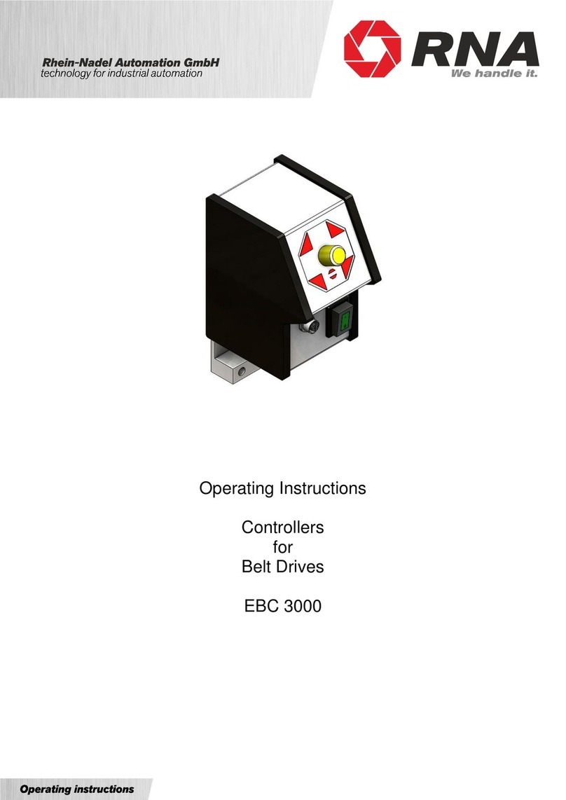
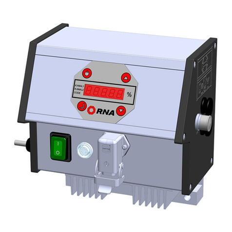
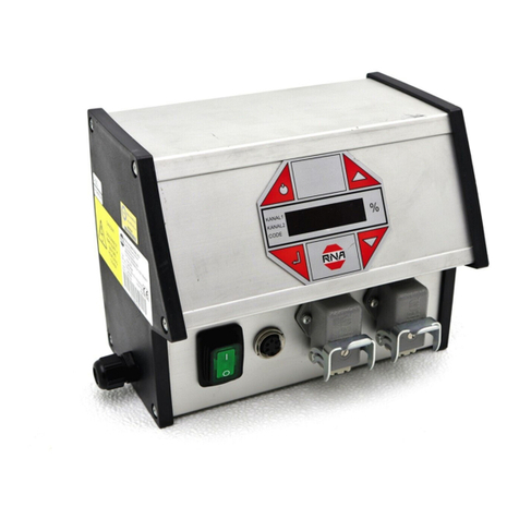
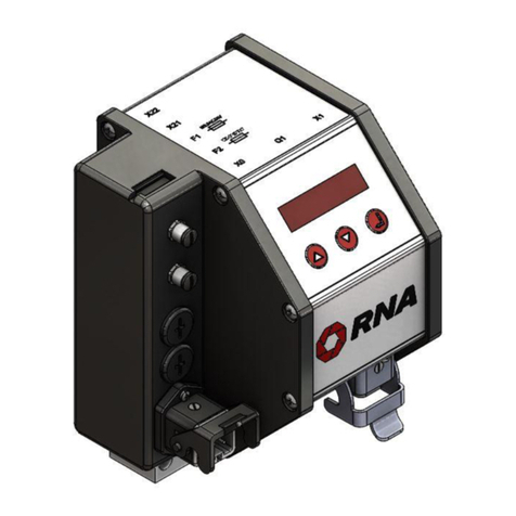
RNA SCU2000 User manual

Operating Instructions
Controllers
for
Vibratory Drive Systems
SCU2000

Rhein-Nadel Automation GmbH 2
VT-BA-SCU2000_EN_2023.docx
Table of Contents
1. About this document ..............................................................................................................4
1.1. Document description:......................................................................................................4
2. Safety information..................................................................................................................4
2.1. Design of safety directives ...............................................................................................4
2.2. Fundamental safety directives..........................................................................................4
2.3. Personnel.........................................................................................................................4
2.4. Intended use ....................................................................................................................5
2.5. Residual hazards .............................................................................................................5
2.5.1. Device ........................................................................................................................5
2.5.2. Protection of the drive system....................................................................................5
2.5.3. Degree of protection - Protection of persons and equipment .....................................6
3. Product information................................................................................................................6
3.1. Functional description ......................................................................................................6
3.2. Difference between SCU1000 and SCU2000 ..................................................................6
3.3. Technical data..................................................................................................................7
3.4. Products, spare parts and accessories ............................................................................8
4. Notes on start-up....................................................................................................................8
4.1. Modes of operation...........................................................................................................8
4.2. Automatic mode change...................................................................................................9
4.3. Start/Stop by external controller.......................................................................................9
4.4. Status signals to an external controller...........................................................................11
4.5. Changing the supply voltage..........................................................................................12
4.6. Measuring the output voltage or output current..............................................................13
5. Connections on the controller...............................................................................................13
5.1. SCU2000........................................................................................................................13
6. SCU2000 connection diagram .............................................................................................14
7. Operation of SCU2000.........................................................................................................15
7.1. SCU2000 menu structure...............................................................................................16
7.2. Description of SCU2000 parameters..............................................................................17
8. Dimensional drawing of SCU2000 .......................................................................................18

Rhein-Nadel Automation GmbH 3
VT-BA-SCU2000_EN_2023.docx
Declaration of Conformity
According to the Low-Voltage Directive 2014/35/EU
and Electromagnetic Compatibility Directive 2014/30/EU
We hereby declare that the product meets the following requirements:
Low-Voltage Directive 2014/35/EC
Electromagnetic Compatibility Directive 2014/30/EU
Applied harmonised standards: DIN EN 60204 T1
EN 61439-1
Remarks:
Rhein-Nadel-Automation
---------------------------------
Managing Director
Jack Grevenstein

Rhein-Nadel Automation GmbH 4
VT-BA-SCU2000_EN_2023.docx
Attention
Read this document carefully and observe the safety directives before commencing any work.
The information given in this document reflects the following version:
Product
from software version
Date
SCU2000
V1.0
2019-03-01
This document provides assistance in choosing your product. You will also find information on mechanical
and electrical installation, product extensions and accessories.
Notice
This notice identifies useful tips for use of the controller.
Attention!
This symbol identifies hazardous situations.
Non-observance of such warnings may cause irreversible injury or even death!
Non-observance of the following fundamental safety measures and directives may lead to severe injury and
damage to property!
Meeting the requirements given in the related documentation is a precondition for safe and trouble-free op-
eration and for achieving the product properties specified. Further additional safety directives in the other
sections must be observed as well.
Attention!
Any work on electrical equipment of the machine/system shall be carried out exclusively by a
professional electrician, or by instructed persons working under the direction and supervision of a
professional electrician, according to electrotechnical rules.
Only qualified professionals are allowed to work on or with the product. IEC 60364 or
CENELEC HD 384 define the qualification of these persons:
•They are familiar with set-up, installation, commissioning and operation of the product.
•They possess the qualification required for performance of their work.
•They know all regulations for the prevention of accidents, directives and laws applicable to set-
up, installation and commissioning on site, and they are able to apply the same.
•They have knowledge and skills of First Aid.
1. About this document
1.1. Document description:
2. Safety information
2.1. Design of safety directives
2.2. Fundamental safety directives
2.3. Personnel

Rhein-Nadel Automation GmbH 5
VT-BA-SCU2000_EN_2023.docx
Please observe the following directives for intended use of the controllers:
•The devices herein described must only be stored, fitted and operated under the conditions spec-
ified in this documentation.
•Here you are not concerned with domestic devices! They are solely intended to be used as com-
ponents for commercial or professional applications pursuant to EN 61000−3−2.
•They satisfy the protection requirements of 2014/35/EU: Low Voltage Directive.
•They do not constitute a machine as defined by 2006/42/EU: Machinery Directive.
•A machinecomprising the productmust not becommissioned or put into operationfor theintended
use until it has been declared to be in conformity with the EC Directive 2006/42/EU: Machinery
Directive; Observe EN 60204−1.
•Commissioning or starting operation for the intended use is only permitted in compliance with the
EMC Directive 2014/30/EU.
•Use of the product in living areas may lead to EMC disturbance. The user is responsible for taking
interference suppression measures.
•They are optimised for operation of RNA vibratory feeders and linear feeders. Observe the limits
indicated in the technical specification.
Attention!
•Prior to start-up make sure that the protective earth conductor is connected and in proper
condition. Make the PE conductor test with approved test devices only.
•Never start up despite detected damage.
•Do not make any technical modifications to the device, except as described in this docu-
ment.
•Never start up in an incompletely installed state.
•Never operate the device without the required guards in place.
•Connect, disconnect or change any electrical connections only in the absence of voltage.
Residual hazards may remain even if all directives have been observed and protective measures taken.
Such residual hazards must be considered by the user in the risk assessment of his machine/equipment.
Non-observance may lead to severe injury and damage to property!
Pay attention to the warning signs fitted to the device!
Symbol
Description
Hazardous voltage:
Prior to commencing any work on the product check for absence of voltage on all power con-
nections.
Leakage current:
Make fixed installation and PE connection according to EN 60204−1!
Certain device parameter settingsmay cause ofheating of theconnected drive magnet, e.g., due to prolonged
operation with improper boost factor.
2.4. Intended use
2.5. Residual hazards
2.5.1. Device
2.5.2. Protection of the drive system

Rhein-Nadel Automation GmbH 6
VT-BA-SCU2000_EN_2023.docx
•All specifications relate to installed condition ready for operation.
•All slots not used must be closed by protection caps or dummy plugs in order not to reduce the pro-
tection against accidental contact.
The compact controller can operate all RNA vibrating motors up to a load current of 6 amps. It is designed
for individual installation right local to the vibrating drive.
The controller is customized for RNA vibratory drive systems. The feed rate can be precisely adjusted within
the setting range via LED display. Thanks to this new control technology the feed rate is kept largely constant
even with fluctuating supply voltage.
The illuminated rocker switch on the controller front panel disconnects all poles from power supply. For fre-
quent switching applications or when operating with a higher-level control system provision is made for ena-
bling via a 16V-30V DC signal. Moreover, the current operating status of the control system can bemonitored
by means of a ‘READY’ or ‘ACTIVE’ signal.
The integrated ramp function ensures time-controlled increase or decrease of the feed rate to setpoint after
starting or stopping. These times are preset at 1 second and 0.2 seconds and can be changed on the con-
troller if necessary.
The controller can operate on both 230V and 115V supply which can be selected on an internal switch. All
other controller settings are made via the LED display.
The SCU1000 has a permanently connected power cable with shockproof plug. The vibrating drive is con-
nected to the SCU1000 by plug. If an enabling signal is required the corresponding wiring can be fed into the
device through an M8x1 cable gland and connected to the internal terminals. Status signals are not brought
out of the controller.
The SCU2000, however, has all connections pluggable. This means: power supply, vibrating motor, enabling
signal and status signals can all be plug-connected.
2.5.3. Degree of protection - Protection of persons and equipment
3. Product information
3.1. Functional description
3.2. Difference between SCU1000 and SCU2000

Rhein-Nadel Automation GmbH 7
VT-BA-SCU2000_EN_2023.docx
Attention!
Any intervention on the controller shall void the manufacturer's warranty.
This does not apply to
- proper change of supply voltage
- proper connection of external enabling signal
in compliance with this operating instructions manual
3.3. Technical data
Technical data
Power supply (can be changed internally):
230V AC, 50/60Hz, +10 -10%
or
115V AC, 50/60Hz, +10 -10%
Output voltage:
Ueff 40...208 V variable, (230V supply)
Ueff 20...105 V variable, (115V supply)
Load current:
max. 6 A(Ieff)
Device fusing (power input):
2x miniature fuse 5 x 20mm
M6.3A/250V AC
Operating modes:
(depending on 50/60 Hz supply frequency)
Mode 1:
asymmetric half-wave mode
(vibrating frequency = mains frequency)
3000/3600 1/min
Mode 2:
symmetric full-wave mode
(vibrating frequency = double mains frequency)
6000/7200 1/min
Mode change:
Coding jumper in load connector
Enabling of functions:
internal/external
adjustable via parameters
Enabling input, external contact:
floating contact
Voltage source load capability: 24V DC, <10 mA
Enabling input, external 24V signal:
Level 16...30 VDC (polarized)
Signal current at 24V DC: < 10 mA
Status outputs
2x 24V DC, max. 30mA
Power loss:
max. 18W
Soft start / stop
Standard start1s, stop 0.2s
adjustable via parameters
Leakage current
Less than 2mA
Degree of protection:
IP 54
Radio interference suppression:
acc. to EMC directive
Dimensions:
130 x 203 x 135 (width x height x depth)
Ambient temperature:
0°C to 40°C
Bearing temperature
-20°C to 70°C
Air humidity:
15% to 85% not condensing
Air pressure:
86 kPa to 106 kPa
Cooling:
free convection
Weight:
approx. 1.6 kg
Housing material:
Aluminium/plastics
Installation position:
Vertical
Mounting
vibration-free

Rhein-Nadel Automation GmbH 8
VT-BA-SCU2000_EN_2023.docx
Designation
Design
RNA article code
SCU2000
completely pluggable
with enabling and status signals
with power input cable
31002816
Designation
Connector
Design
RNA article code
Power input cable
SCU2000
X0
Length: 1.9 m
Shockproof plug and power plug (SCU2000)
31002811
Vibrating drive
connector
X1
Male connector, 4 poles + PE
Metal housing
31002323
(100Hz drive)
Vibrating drive
connector
X
Male connector, 4 poles + PE
Metal housing
31002322
(50Hz drive)
SCU2000 con-
necting cable for
enabling and sta-
tus signals
X21
X22
Length: 5.0m
Female connector M8, 4 poles, straight
Halogen-free PUR, open cable end
35051663
Length: 5.0m
Female connector M8, 4 poles, right-angled
Halogen-free PUR, open cable end
35051664
Designation
Description
RNA mat. code No.
Measuring
adapter
ESZ-02
(400V/10A)
Accessory for measurement of output voltage and output current. The
adapter is supplied with connectors.
31002525
Attention!
Set the controller to minimum output before switching-on for commissioning or start-up after re-
pairs or replacement of controllers/vibratory drives. Then check for proper operation while the
output is increased.
RNA vibratory drive systems employ mechanical spring vibrators which are set to a vibrating frequency near
the mains frequency or near double mains frequency depending on weight and/or size.
This is why two modes of operation are possible:
Mode 1: Asymmetric half-wave mode:
The vibrating drive operates at mains frequency.
Mode 2: Symmetric full-wave mode:
The vibrating drive operates at double mains frequency.
To assist the operator the cable glands on the drive connector are colour-coded.
Mode 1: Black
Mode 2: grey
In terms of the vibrating frequency this means:
Mains frequency 50 Hz
Mains frequency 60 Hz
Cable gland colour
Mode 1
Half-wave mode
Vibrating frequency
50 Hz ≙3000 min-1
Vibrating frequency
60 Hz ≙3600 min-1
Black
Mode 2
Full-wave mode
Vibrating frequency
100 Hz ≙6000 min-1
Vibrating frequency
120 Hz ≙7200 min-1
grey
3.4. Products, spare parts and accessories
4. Notes on start-up
4.1. Modes of operation

Rhein-Nadel Automation GmbH 9
VT-BA-SCU2000_EN_2023.docx
Vibratory drive systems by RNA do not require the operator to take care of selecting the right operating mode.
The operating mode is determined by a code in the RNA vibrating drive connector. A wire jumper from pin 3
to 4 in the connector switches the controller to mode 2: 100 or 120 Hz. In the absence of this wire jumper the
controller operates in mode 1: 50 or 60 Hz.
The RNA vibratory drive systems come with the right code in the connector.
Mode changes are made only and exclusively via the coding in the vibrating drive connector!
(Where frequency controllers with selectable output frequency are used, an EMC metal gland and a shielded
cable are provided.)
With the default setting the vibrating drive is started/stopped by the power switch of the controller. The exter-
nal enabling input makes it possible to control the vibrating drive by a higher-level control system.
Notice
Non-observance of these directives may lead to malfunctions or defects of the controller.
Attention: Connectors X21 and X22.
Controllers with serial numbers before A889494 came with female connectors.
Controllers with serial number A889494 and higher come with male connectors.
The pin assignments are identical in both versions.
There are two options provided for external enabling:
Voltage signal:
This type of enabling should be preferred.
If a direct voltage between 16 and 30 V is available with the correct polarity the vibrating drive starts. The
input is protected against polarity reversal.
Observe the following directives:
•Cable length max. 10m.
•Avoid cable routing in the immediate vicinity of high-energy switching devices or strong interference
fields.
4.2. Automatic mode change
4.3. Start/Stop by external controller
M20 gland
Black: 50/60Hz vibrating frequency
Grey: 100/120Hz vibrating frequency
(EMC metal gland if frequency controllers are used.)

Rhein-Nadel Automation GmbH 10
VT-BA-SCU2000_EN_2023.docx
Connection for the 24V signal is made with connector XS21.
Pin
Pre-assembled cable
1
not used
Brown
2
not used
White
3
GND (0V DC)
Blue
4
+24V DC (ext.volt.)
Black
See also connection diagram of SCU2000, chapter 5.
Floating contact:
If no 24 V signal is available, enabling is also possible via a floating contact. Closing of the contact enables
the controller and starts the vibrating drive.
Connection is made via terminals inside the controller.
Observe the following directives:
•Cable length max. 5m.
•Use shielded cable for lengths of 3m and more.
•Avoid cable routing in the immediate vicinity of high-energy switching devices or strong interference
fields.
Use terminal block X2 to connect the floating contact inside the controller.
Remove the top blanking plug (M16x1.5) and replace it with a plastic cable gland (M16x1.5).
The cable gland must be suitable for the cable diameter and have a thread length of 8mm max.. Afterwards
the fuse behind the gland can only be reached by opening the device.
Insert a cable with a cross-section of 2x0.25mm² min. to 2x0.5mm². max. Connect the cores to terminals 7
and 8. See also illustration on page 11 (position of terminals inside device).
Make sure that the required protection rating (IP54) is maintained. Take care to ensure that the cable gland
corresponds to at least protection class IP54 when installed. It is also mandatory to observe the required
torques and cable diameters according to manufacturer specifications.
For safety reasons the cable gland used must be plastic.
It is not permitted to enlarge the existing hole or otherwise modify the housing.
Connection of external enabling signal to SCU2000 via floating contact
Attention!
Any work on electrical equipment shall be carried out exclusively by a professional electrician, or
by instructed persons working under the direction and supervision of a professional electrician,
according to electrotechnical rules.

Rhein-Nadel Automation GmbH 11
VT-BA-SCU2000_EN_2023.docx
Observe the safety directives in chapter 2.
Connection for external enabling signal:
- Disconnect the device from power supply.
- Open left side of the device
- Remove the upper blanking plug (M16x1.5)
- Fit a plastic cable gland (M16x1.5) in the existing hole
- Feed the signal cable through the gland and connect it
- Close left side of the device
- Connect device to power supply
- Make a test run to test the enabling signal
Terminal X2
Nominal cross-section:
0.5 mm²
Stripping length:
11 mm
Conductor cross-section AWG min. / max.
26 / 20
External enabling parameter assignment.
The external enabling functionality must be set by the Hi parameter in the parameters menu. See chapter 7.
Following status signals are available to a higher-level control system:
READY status signal:
The READY signal is sent when the controller is energized by its power switch closed.
ACTIVE status signal:
The ACTIVE signal is switched on and off together with the vibrating drive.
Connection is made with connector XS22.
4.4. Status signals to an external controller
Attention!
Connectors X21 and X22.
Controllers with serial numbers before A889494 came with female connectors.
Controllers with serial number A889494 and higher come with male connectors.
The pin assignments are identical in both versions.
SCU2000:
7 = enabling via external contact
8 = enabling via external contact
1
8
X2

Rhein-Nadel Automation GmbH 12
VT-BA-SCU2000_EN_2023.docx
Pin
Pre-assembled cable
1
+24V DC (ext.volt.)
Brown
2
Ready
White
3
not used
Blue
4
Active
Black
See also connection diagram of SCU2000, chapter 5.
The controller is designed to operate both on 230V, 50/60Hz and on 115V, 50/60Hz. The given operating
voltage must be set on the selector switch in the controller.
As delivered, the devices are set to the supply voltage indicated in the purchase order.
Attention!
Any work on electrical equipment shall be carried out exclusively by a professional electrician, or
by instructed persons working under the direction and supervision of a professional electrician,
according to electrotechnical rules.
Having changed the supply voltage take utmost care in re-assembling the controller because oth-
erwise the operating permit or manufacturer's warranty will become void!
Setting the wrong supply voltage may result in electrical or mechanical damage to the controller
or vibrating motor.
Changed devices should be marked conspicuously to avoid confusion.
Changing 230V / 115V:
- Disconnect the device from power supply.
- Open left side of the device
- Set switch to required
position
- Close left side of the device
- Connect device to power supply
- Trial run
4.5. Changing the supply voltage
115
230
Supply voltage selection
top => 115 V
bottom=> 230 V

Rhein-Nadel Automation GmbH 13
VT-BA-SCU2000_EN_2023.docx
In some cases it may be necessary to measure the output current or output voltage.
Attention!
This measurement must be made by qualified professionals only. Having completed the measure-
ment take utmost care in re-assembling the controller because otherwise the operating permit will
become void!
Notice
The measuring device must be designed for true root mean square measurement (true RMS).
Other measuring devices would show random values.
The output voltage can only be measured with the vibrating drive connected! The load connector
must be plugged in because otherwise the measurement may perhaps be made in the wrong
operating mode.
The use of the measuring adapter ESZ-02 (see chapter 1.6) greatly facilitates measurement of the output
voltage and current. The measuring adapter is fitted with appropriate connectors for easy connection between
controller and vibrating drive. The use of moving-iron measuring instruments makes sure that the true root
mean square value is measured.
Attention!
When replacing the fuse be sure to use the specified rating of M6.3A/250V.
Too high a fuse rating may destroy the controller.
4.6. Measuring the output voltage or output current
5. Connections on the controller
5.1. SCU2000
X2
2
Status output
X2
1
Enabling input
F1
Access to fuses
F2
Power supply con-
nector
X
0
Power switch
Connection for vi-
bratory feeder
X1

Rhein-Nadel Automation GmbH 14
VT-BA-SCU2000_EN_2023.docx
Attention!
Connectors X21 and X22.
Controllers with serial numbers before A889494 came with female connectors.
Controllers with serial number A889494 and higher come with male connectors (see connection
diagram above).
The pin assignments are identical in both versions.
6. SCU2000 connection diagram
Drive
max. 6A
Supply
voltage selector
External enabling
contact
External enabling
24VDC
ready
active
wire jumper
not used for 50/60 Hz
required for 100/120 Hz
floating
contact
PLC output
ready
active

Rhein-Nadel Automation GmbH 15
VT-BA-SCU2000_EN_2023.docx
LED display:
A short while after starting of the controller the status display comes up and the set feed rate is shown.
Other potential display readings:
External enabling signal missing or wrong parameter assignment.
The parameter b (Boost) has been changed from 1.0 to another value.
Supply voltage too low.
(This message appears for a few seconds when the device is switched on or off.)
Buttons:
Using the arrow buttons you can change setpoints and scroll through the menu.
Press the ENTER button to apply the values changed.
Changing the feed rate:
Upon pressing of the ENTER button the decimal point starts blinking on the status display and you can set
the feed rate using the arrow buttons. Press ENTER again to complete the entry. The decimal point stops
blinking.
Opening the parameters menu:
Press both arrow buttons at the same time. The parameters menu will comeup after one second. The display
shows the first parameter with its set value. Using the arrow buttons you can scroll through the list of param-
eters. For description of parameters see below.
Changing parameters:
Press the ENTER button to change a parameter. While the decimal points are blinking you can change the
parameter using the arrow buttons. Press ENTER again to complete the entry. The decimal points stop blink-
ing.
Exiting the parameters menu:
Scroll through the parameters menu until the display shows End. Press ENTER to see the status display.
The status display will also appear if you press both arrow buttons at the same time for one second.
7. Operation of SCU2000
Attention!
Improper setting of this parameter creates the risk of overheating the magnets.
STOP
75.0
_75.0
LoPo

Rhein-Nadel Automation GmbH 16
VT-BA-SCU2000_EN_2023.docx
Display:
Boost factor ≠ 1.0 (for full-wave only)
Output inhibited by
missing enabling signal
Förderleistung0...100%
I=Freigabeeinganginvertiert
Sanftanlauf:0...10s
Sanftauslauf:0...10s
minimaleFörderleistung(Umin):0...35%
Boostfaktor:0.8...1.2
zurSchwingantriebsanpassung
(nurimVollwellenbetriebwirksam)
SchwingfrequenzAnzeige:
2=Vollwelle(100 Hz)
I=Halbwelle (50 Hz)
SoftwareVersion
RückkehrzumBetriebsanzeige
I=Schnellmenügesperrt
1s
1s
Schnellmenü
7.1. SCU2000 menu structure
Up
Down
ENTER
Display
Status display
feed rate 0 … 100 %
feed rate 0 … 100 %
I = enabling input inverted
soft start. 0….10s
soft stop: 0…10s
boost factor: 0,8…1,2
for vibrating motor adjustment
(only effective in full wave mode)
minimum feed rate (Umin): 0…35%
I = quick menu inhibited
vibrating frequency display
2 = full wave (100 Hz)
1 = half wave (50 Hz)
software version
return to status display

Rhein-Nadel Automation GmbH 17
VT-BA-SCU2000_EN_2023.docx
Attention
Setting of wrong parameters may result in electrical or mechanical damage to the controller or
vibrating motor.
Therefore, set a low feed rate on the controller before starting. Then check for proper operation
while the output is increased.
Description of parameters in the parameters menu.
Feed rate setting in %.
Can be set from 0 ... 100%.
Can also be changed in the status display (if PSP parameter at 0).
External enabling function.
1= Vibrating drive starts without ext. signal and stops when the external signal is present.
0= Vibrating drive stops without ext. signal and starts when the external signal is present.
Soft start time, run-up time from feeder start.
Adjustable from 0 ... 10s, default setting is 1s.
Soft stop time, run-down time from feeder stop.
Adjustable from 0 ... 10s, default setting is 0.2s.
Boost factor, can be set from 0.8 to 1.2. Only effective in full-wave mode (100/120Hz).
Default setting 1.0
Changing the boost factor is not necessary in normal operation. Such change is only re-
quired in case of special vibrating drive systems.
Attention!
Improper setting of the boost factor will overheat the connected magnets.
Lower limit of feed rate.
Can be set from 0 to 35%.
Disabling feed rate adjustment in the status display.
0 = enable (default setting)
1 = disable
Now you can adjust the feed rate via parameter oonly.
Display of operating mode or vibrating frequency (only with vibrating drive connected):
1 = 50/60Hz (half wave)
2 = 100/120Hz (full wave)
The change of operating mode or vibrating frequency takes place only via coding in
the vibrating motor connector. See chapter 4.2.
Indication of the controller software version.
Return to status display.
7.2. Description of SCU2000 parameters
o.75.0
Hi.1
b. 1.0
0.2
. 0.2
PL. 35
P.s.p. 0
HA. 1
5.no.
End

Rhein-Nadel Automation GmbH 18
VT-BA-SCU2000_EN_2023.docx
All dimensions in mm
8. Dimensional drawing of SCU2000

Rhein-Nadel Automation GmbH 19
VT-BA-SCU2000_EN_2023.docx
Headquarters
Rhein-Nadel Automation GmbH
Reichsweg 19-23
D-52068 Aachen
Phone: +49 (0)241-5109-0
www.RNA.de
Further RNA group companies:
PSA Zuführtechnik GmbH
Steinäckerstraße 7
D-74549 Wolpertshausen
Phone: +49 (0)7904-94336-0
www.psa-zt.de
RNA Automation Ltd.
Unit C Castle Bromwich Business Park
Tameside Drive Birmingham B35 7AG
Great Britain
Phone: +44 (0)121-749-2566
E-Mail: sales@rnaautomation.com
www.rnaautomation.com
HSH Handling Systems AG
Wangenstraße 96
3360 Herzogenbuchsee
Switzerland
Phone: +41 (0)62-956 10-00
E-mail: info@handling-systems.ch
www.handling-systems.ch
RNA Vibrant S.A.
Carrer de l'Energia
08940 Cornella de Llobregat (Barcelona)
Spain
Phone: +34 (0)93-377-7300
E-mail: info@vibrant-RNA.com
www.vibrant-RNA.com
RNA Digital Solutions GmbH
Agnes-Pockels-Bogen 1
D-80992 München
Phone: +49 (0)1515-99 28 255
E-mail: kontakt@rnadigital.de
www.designforfeeding.com
www.rnadigital.de
Further manufacturing sites
of the RNA Group
Lüdenscheid site
Rhein-Nadel Automation GmbH
Nottebohmstraße 57
D-58511 Lüdenscheid
Phone: +49 (0) 2351 -41744
E-mail: werk.luedenscheid@RNA.de
Ergolding site
Rhein-Nadel Automation GmbH
Ahornstraße 122
D-84030 Ergolding
Phone: +49 (0) 871 -72812
E-mail: werk.ergolding@RNA.de
Remchingen site
Rhein-Nadel Automation GmbH
Im Hölderle 3
D-75196 Remchingen-Wilferdingen
Phone: +49 (0)7232-7355-558
E-mail: werk.remchingen@RNA.de
Table of contents
Other RNA Controllers manuals
Popular Controllers manuals by other brands

Smartgen
Smartgen HAT530 user manual

HomeMatic
HomeMatic HM-LC-Sw1-DR Installation and operating manual

VERDER
VERDER Carbolite Gero Chessell 6100A Installation, operation and maintenance instructions

Dakota Digital
Dakota Digital PAC-2700 manual

Immergas
Immergas CARV2 Instruction and warning book

Dometic
Dometic GP-MPPT-60/10 user manual