Equipment Check List: Not Supplied
IMPO TANT
IPlease ensure the consumer guarantee card enclosed with this product is completed and returned to Roman; please ensure the end user retains this manual.
IPlease read all instructions carefully before attempting installation.
IHandle the product with care to avoid damage to the product finish.
ICheck for hidden electrical cables and water pipes prior to commencing any drilling work.
IImages are used for illustration purposes only, product designs may differ slightly as a result of continuing product development.
IRoman Sculptures enclosures are heavy, this enclosure installation must be carried out by a minimum of two people to avoid possible lifting injury and damage
to the large glass panels.
IRoman’s toughened glass is completely safe for use in our shower enclosures and bath screens; providing our products are installed according to our guidelines.
IIt is important to note, that the glass must not be mounted or ‘pinched’ in such a way that would cause a stress point to develop in the glass. In addition, it
must not be subjected to any sharp impact or severe temperature fluctuation which may also cause a stress point to develop in the glass.
IRoman’s toughened glass is physically and thermally significantly stronger than standard glass. During our toughening process the stresses contained within any
glass are balanced so if in the unlikely situation any of the above occurs and the glass breaks, the glass will shatter safely into small thumbnail sized blunt
fragments.
Ref: SFC/May 10
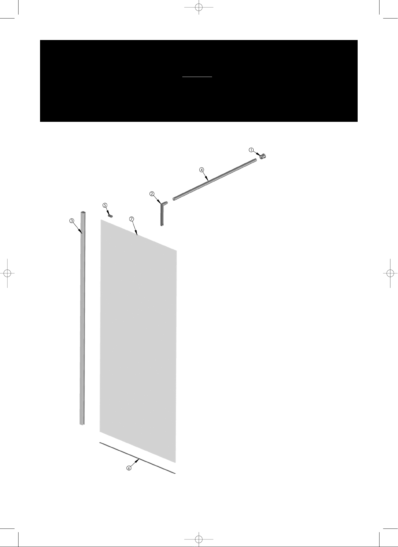
Corner Panel
Instruction Manual
Description
PZ2 Pozidrive screwdriver
Bathroom Sealant Gun
Spirit level (large)
Drill and 6mm Masonry Bit 2
Tape Measure
Pencil
Allen Keys (supplied)
Hack Saw (suitable for cutting stainless steel)
Component Check List: Supplied
Description Quantity
Brace Bar Wall Joint 1
Brace Bar High-Level Panel Joint 1
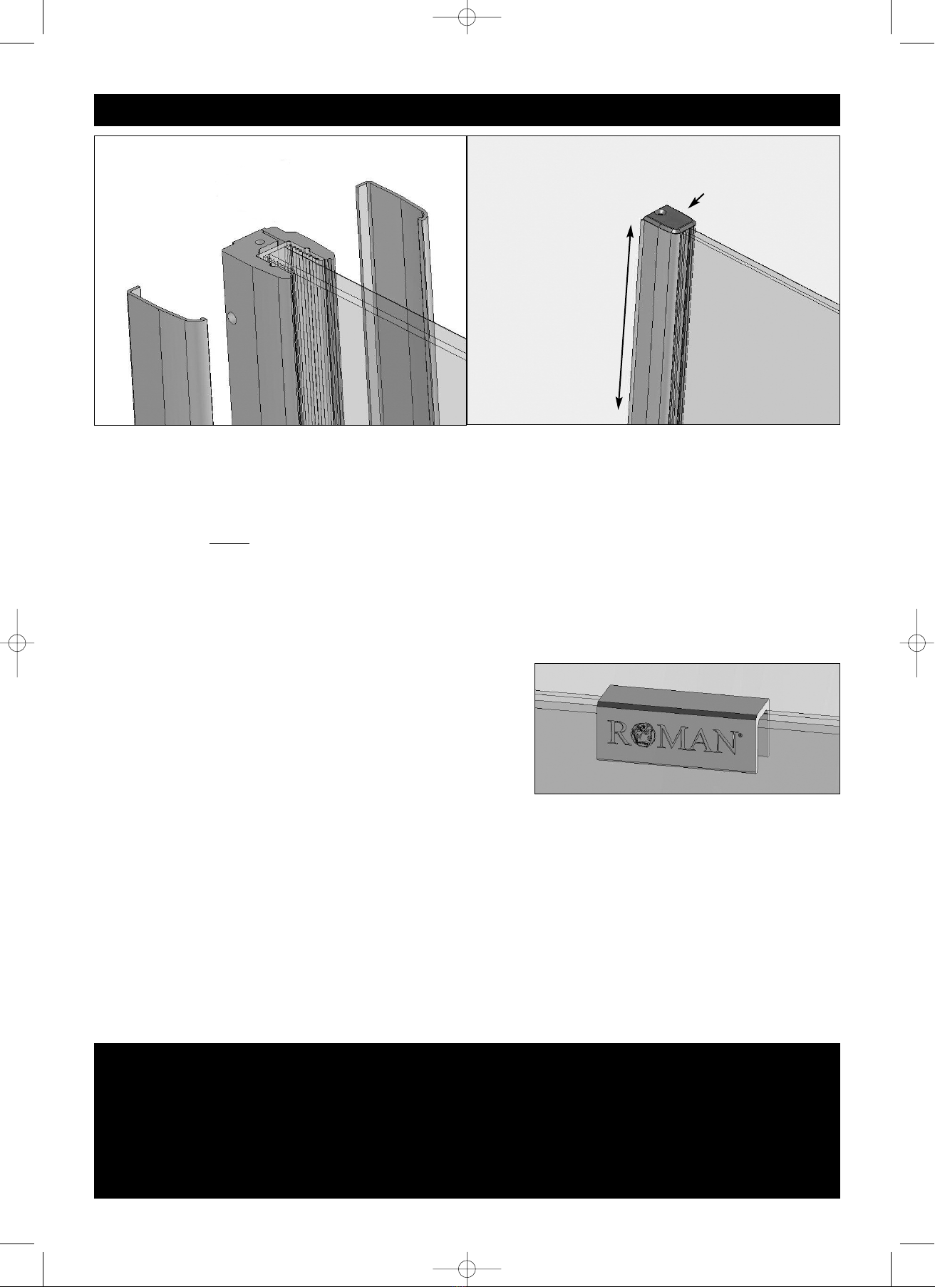
Wall Profile System 1
25mm Brace Bar 1
Roman Branding Clip 1
Floor to Panel Protector 1
10mm Toughened Glass 1
Use
-multi-purposeglassprotector
onthisproductforalong
lastingsparkle.
(Seeinsidefor information)
Please make sure the purchaser/end user completes and returns the Guarantee card which is enclosed with this
product or registers on line at www.roman-show rs.com/r gist r_guarant .htm. Failure to validate
the Roman Truelife Guarantee will mean only the 1 Year Statutory Guarantee will apply.
Truelife Consumer
Guarantee
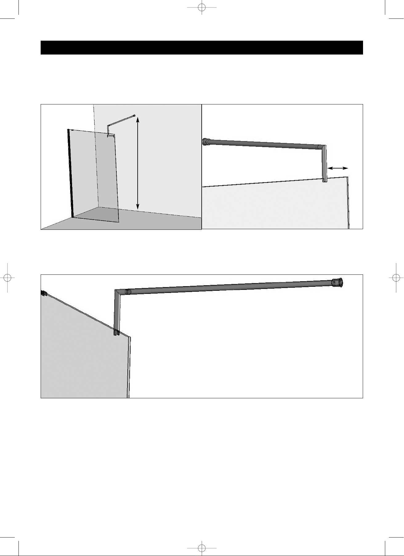
Site equirements
Walls
The walls to which the enclosure is to be fitted to must be vertical with no more than 5mm deviation. A maximum of 5mm adjustment is provided within the enclosure
to take account for untrue walls.
Tray
If fitting to a tray the following requirements must be met before installation can commence:
IThe tray must be a Roman product.
IThe tray must be fitted according to the Roman instruction manual supplied with the tray.
IAny tiling of the walls must not overhang the tray by more than 5mm. The tray can be offset from the wall to achieve this, see next page.
IAny tiling and sealing around the tray and enclosure area must be completed and fully dry.
IInnssttaallllaattiioonn SSiittee PPrreeppaarraattiioonn
S c u l p t u r e s