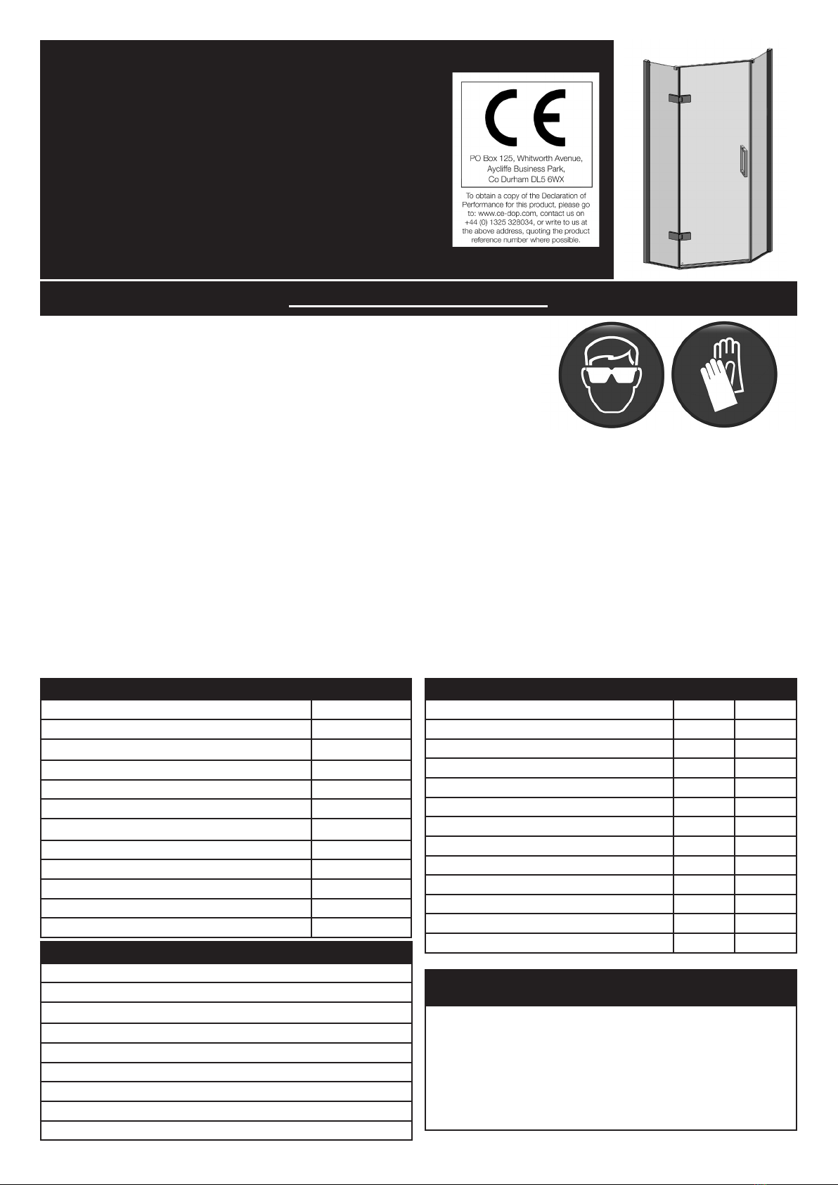
Ro-Man Neo Angle DXP User manual

Neo Angle
Instruction Manual
DXP
IMPORTANT INFORMATION
Be aware toughened glass can shatter if not handled correctly. It should not
be subjected to any sharp impact and it is essential to protect the glass by
resting it on a soft protective surface during installation such as cardboard
or carpeting. It is recommended to wear PPE at all times during installation.
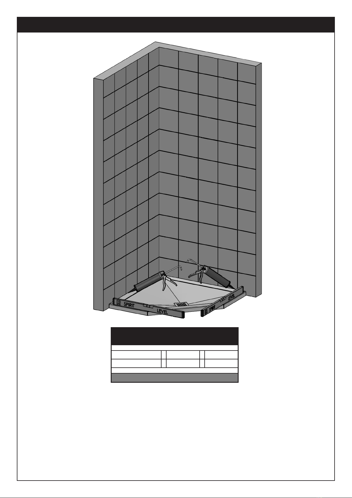
Component Check List: Supplied
Description Quantity
Wall Proles / Wall Prole Top Caps 2 of each
Wall Prole Covers 4
Hinge Panel Assembly / Plain Panel Assembly 1 of each
Door Glass 1
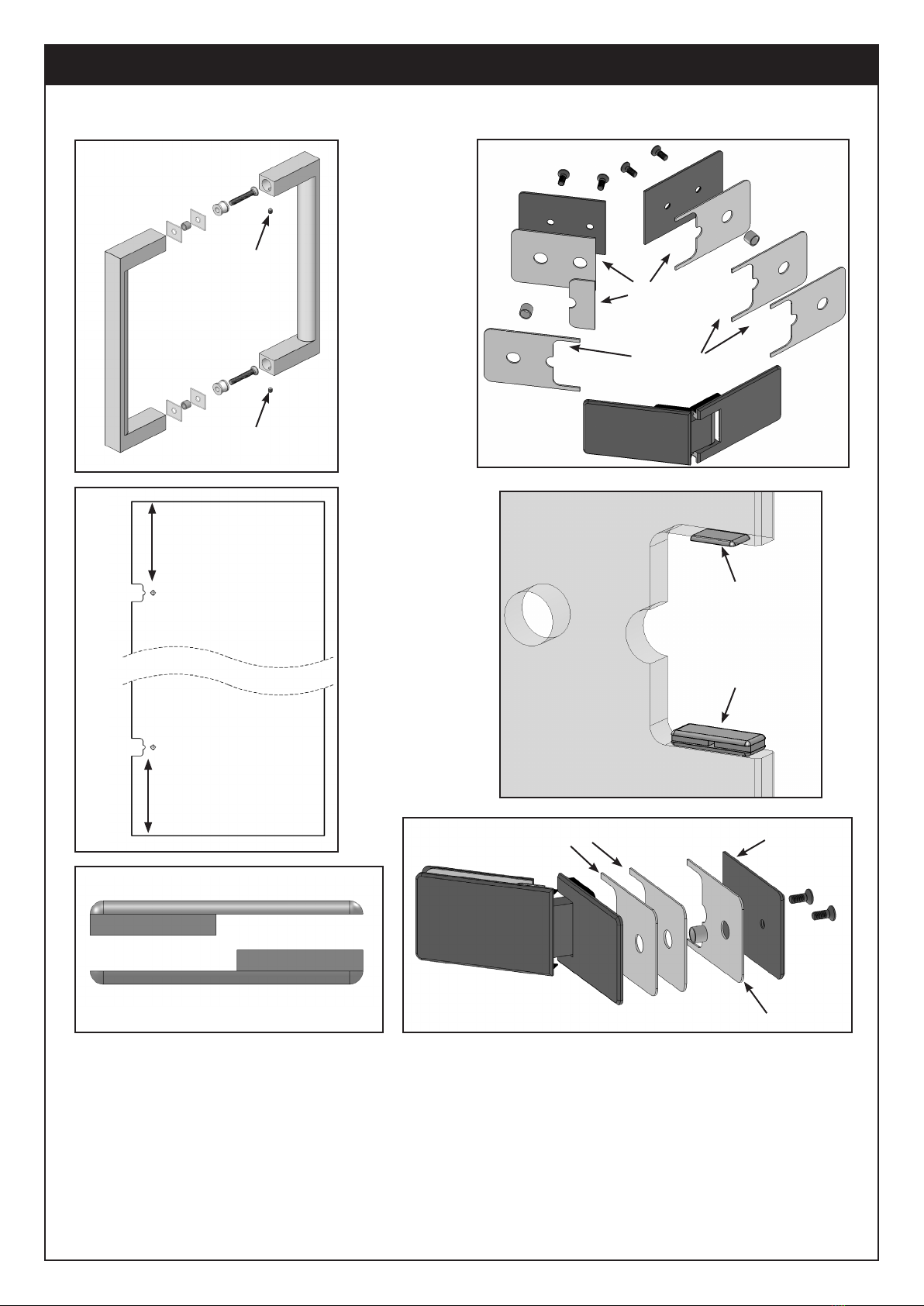
Braciing Assembly / Handle Assembly 1 of each
Hinge Assemblies 2
Door Joints (Left and Right Hand) 1 of each
Bottom Rails 3
Door Rail (Sloped) 1
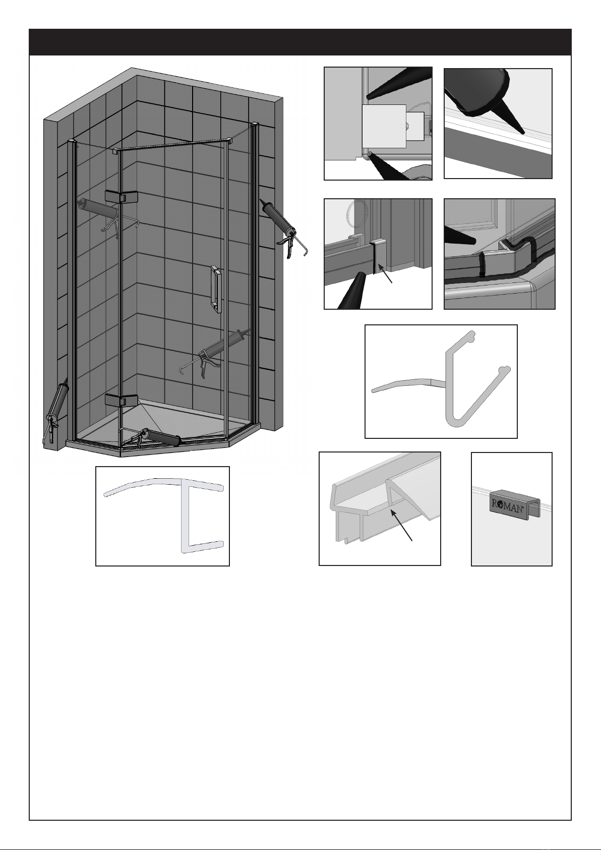
Vertical Panel and Vertical Door Seal 1 of each
Door Bottom Seal 1
Fixing Kit Components Quantity
Description Door Panels
2.5mm Drill Bit - 1
9mm long Cap Head Screws - 20
9mm long Csk Head Screws - 4
40mm long Cap Head Screws - 16
Wall Plugs (Brown) - 16
Branding Clip - 1
Door Setting Blocks 4 -
2.5mm Allen Key 1 -
3mm Allen Key 1 -
4mm Allen Key 1 -
Bottom Packers 8 -
Top Packers 4 -
Please make sure the purchaser/end user
completes and returns the guarantee card
which is enclosed with this product. Failure
to validate the Guarantee will mean only the 1
Year Statutory Guarantee will apply.
CONSUMER GUARANTEE
PRE-INSTALLATION CHECKS
1. Check you have the correct product. Please look at the labels on the side of the product packaging.
2. Check all the product components are in the box and the xing kits.
3. Unpack your product and handle it with care.
4. Please check the product for defects or damage, once the installation has commenced we cannot accept responsibility for any defects or damage.
5. Please take time to read these instructions prior to installing your product.
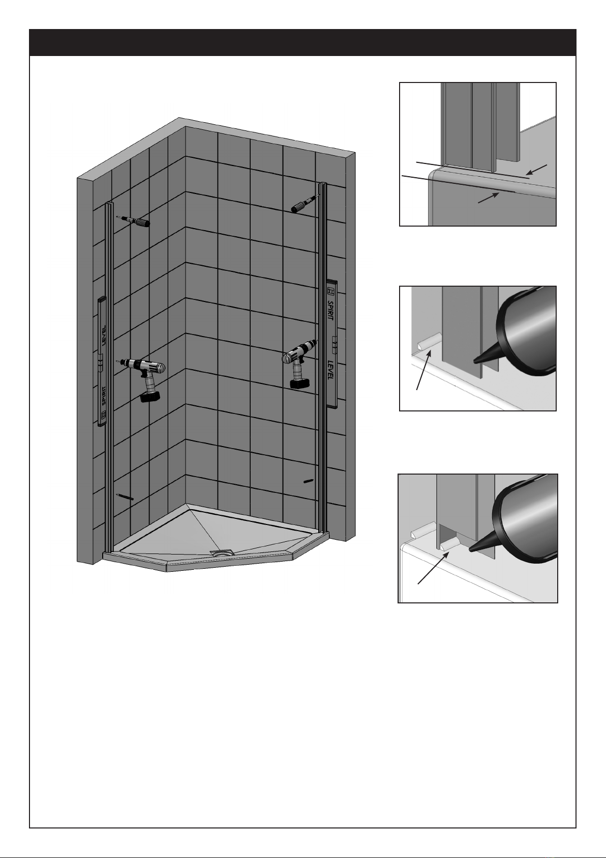
6. Before you commence any drilling check there are no hidden electrical cables and/or water pipes.
7. No attempt should be made to re-work the toughened safety glass.
8. The installation of the product should be performed by two persons.
9. It is strongly recommended that the walls the product is going to be installed on are vertical.
10. It is strongly recommended the product is tted on a tiled surface or similar waterproof surface.
11. It is strongly recommended the walls are tiled and grouted before the product is installed.
12. If the walls and/or the tray are not level you will not achieve maximum adjustment of the product.
13. Pictures used are for illustration purposes only, product designs may alter slightly as a result of continuing product development.
14. We do not stipulate where the European Standard Kite Mark should be positioned on the glass when being factory assembled.
15. Please note that some natural misting may occur when you remove this product from its packaging, due to the addition of the glass protection pre-
coating. If this does occur this can easily be removed with a soft, dry cloth.
Ref: DXP REV2 - SEPT 2019
Equipment Check List: Not Supplied
Description
Electric / Battery Drill
Pozi Screwdriver
Sealant Gun / Sealant
Torque Wrench
Spirit Level (Large)
7mm Masonry Drill Bit
Tape Measure
Pencil

1. Check the tray is level on all sides (the bubble on the spirit level must be in the centre of the 2 lines).
2. Stand in the tray and check that there is no adverse movement (correct if necessary).
3. The walls should be tiled and grouted up to the tray.
4. The tiles and the tray should be sealed using a good quality bathroom sealant.
• Spray the seal and joints with the shower head and check for leaks when the silicon has cured.
• Check the plumbing for leaks.
• DO NOT plasterboard over the tray.
• DO NOT grout the tiles when the enclosure has been tted, the grout may discolour the aluminium
proles.
• Make sure the tray is installed as per the manufacturer’s instructions.
• When all of the above has been completed please proceed to the Step 2.
Step 1 - Pre-Installation Checks and Aperture Sizes
Panel Sizes Minimum Maximum
900 Panel 865 880
1200 Panel 1165 1180
IMPORTANT: The above are nished tiled sizes

Step 2 - Wall Proles
1. Take one of the Wall Proles and position it 12mm in from the outside of the tray.
2. Ensure the Wall Prole is completely vertical using a Spirit Level then using a pencil mark the wall through
the slots.
• Make certain the wall prole is completely vertical using a Spirit Level ( the bubble should be in the
centre of the two lines).
3. Follow the same procedures for the other Wall Prole.
4. Drill the walls using a 7mm Masonry Drill Bit (not supplied) and t the Wall Plugs.
5. Remove any debris and apply a bead of sealant the width of the Wall Proles where they meet the top of
the tray / wetroom oor and the tiled walls.
6. Screw x both Wall Proles to the walls using the 40mm Cap Head screws (supplied) ensuring they are
kept completely vertical and are 12mm in from the outside of the tray.
7. Apply a bead of sealant to the inside of the Wall Proles at the bottom where they meet the top of the tray /
wetroom oor.
• IMPORTANT: Failure to comply with stages 5 and 7 may cause serious water damage and is not covered
under the terms of the guarantee.
①
⑤
⑦
12mm

Step 3 - Fitting the Panels
1. On both Panel Assemblies where the already Bonded Extrusion meets the pretted Bottom Rail Panel
Joint place a small bead of silicon on the underside all the way around.
• NOTE: Carefully remove excess silicon if required.
2. Slide the Panel Bottom Rails over the already Bonded Extrusions and push into the siliconed pretted joint.
3. Carefully lift the Panels into their Wall Proles.
4. Take the Door Bottom Rail (671mm long) and place the Door Joints at each end (no silicone). Place these
parts between both pieces of Panel Glass and bring the Panels together until everything shuts out.
5. Move the Panel Assemblies, Door Bottom Rail and Door Joints until all is equally spaced on the tray.
6. With a Spirit Level ensure that the Panels are vertical and that the distance between the Glass at the top is
the same as it is at the bottom.
• Cut a piece of wood the length of the gap at the bottom, use at the top as an aid to keep the gap parallel.
7. Drill through the grooves in both the Wall Proles using the 2.5mm drill bit (supplied). On both inside and
outside drill two holes approximately 50mm from each end, now drill a hole in the centre of those (3 holes),
now drill two further holes between them (5 holes).
• IMPORTANT: This is drilled and xed inside and outside, 5 xings per side (10 in total per Wall Prole).
8. Fasten together using the 9mm Cap Head Screws (supplied).
Note: Two people will be required to do the following operations.
④
②
①
Pretted
Joint
Bonded
Extrusion
↓
↓
⑧⑦
Vee
Groove
↓
Door
Bottom Rail Door Joint
④Make sure all
these parts shut
out at both ends
Make the same
as the Bottom
Measure Bottom
↓

Step 4 - Bracing, Top Caps, Covers and Bottom Rail.
1. Remove the previously placed Door Bottom Rail and Door joints from between the Panel Glass.
2. Add a bead of silicone at each end of the extrusions at the bottom of the Panels.
3. Insert the Door Rail (Sloped) into the Door Bottom Rail ensuring that they are fully together.
4. Add a bead of silicone to the inside edges of both Door Joints all the way around under the sloped area.
5. Place the Door Rail (Sloped) and Door Bottom Rail between the Glass Panels ensuring that the slope
faces inward towards the shower. Fit the Door Joints over the ends of the now placed rails and onto the
end of the Panels. Make sure that it all closes out, remove any excess silicone as necessary.
6. Remove the Bracing Assembly from it’s packaging, loosen the xing screws and t to the tops of the Panel
Assemblies equally. Ensure the gap between the Panels at the top is the same as the bottom then fully
tighten the Bracing onto the glass (make sure the gaskets are placed between the Bracing and the Glass).
7. Fit the Wall Prole Top Caps onto the Wall Proles, hold in place and drill through the holes on both sides
using the 2.5mm drill bit (supplied). Secure the Caps using the 9mm long Csk Head Screws (supplied).
8. Fit the Wall Prole Covers onto the Wall Proles by locating the small curved feature onto the Wall Prole,
hold in place and push until they are between the Wall Proles and tiled Walls.
⑥
Vee
Groove
⑦
⑦
Silicone
Fixing Screws
③
↓
④
②
⑧
Sloped
↓
Wall Prole
Top Cap
⑤
Curved
Feature
↓
Gaskets
⑤

Step 5 - Fitting the Door
1. Remove the Handle Assembly from it’s packaging and reassemble onto the Door Glass, ensure that the
set screws are tted on the inside of the Door and all gaskets are used between the glass and metal parts.
2. Ensure that you have the Door Glass the correct way round.
3. Unpack the Hinge Assemblies and remove the backplates and gaskets from each.
4. Prior to tting the Hinge Assemblies ensure that 2 Bottom Packers are placed between the Hinge and the
bottom of the glass cut-out and 1 Top Packer is placed between the Hinge and the top glass cut-out.
5. Reassemble the Hinge Assemblies onto the Hinge Panel Glass ensuring the gaskets are tted as shown and
the Packers are in place. Keep the Hinges horizontal and tighten the screws with the Allen Key (supplied).
• IMPORTANT: The screws must be tightened to 10 N/m max.
6. Fully open the Hinge Assemblies ready for tting the Door Glass.
①
Top
②
Bottom
Long
Short
Set Screw
Set Screw
Bottom of Cut-out
Top of Cut-out
1 Top Packer
2 Bottom Packers
④
④
2 Large Packers
⑤
③⑤
Panel
B
A
A
A
A
CInside
Outside
Short
⑥
Panel
Inside
Outside
A
A
A
Long
Backplate
IMPORTANT: Take note how the hinge is assembled and what goes where i.e. Short backplate on the Panel
side, gasket “C” and “B” on the inside of the glass. Likewise one of the “A” gaskets on the inside of the Door.

Step 5a - Fitting the Door (Cont...)
1. Take the Red Door Setting Blocks and slide two together creating an assembly, do the same with the other
two. Fit them over the Bottom Rails at each end between the Panel Glass.
2. Carefully lift the Door Glass onto the Red Door Setting Blocks using the Handle for support.
• NOTE: One person will be required to be on the inside of the enclosure.
3. Follow procedure 4 of Step 5 for tting the packers to the glass cut-outs.
4. Carefully close the Hinge Assemblies onto the Door Glass, ensuring the gaskets and Backplate is tted as
shown in Step 5. Line up the Hinges with the cut-outs in the Door Glass.
5. The gap between the Hinge Panel and Door Glass should be set at approximately 6mm. Fully tighten the
screws.
• IMPORTANT: Tighten the screws to 10 N/m max.
6. Slide the Red Door Setting Blocks apart and allow to fall then remove from the Bottom Rails.
• NOTE: Because of the weight of the Door Glass you may need to gently tap apart using a piece of wood
or similar. Be careful not to damage the Glass or the Bottom Rails.
⑤
Note: Two people will be required to do the following operations.
①
②
↓
↓
④6mm

Step 6 - Sealing and Seals
1. Seal all the Wall Prole Covers to the tiled wall vertically both inside and outside.
• IMPORTANT: Ensure that the Covers are placed between the Wall Proles and Tiled Walls.
2. Seal the outside of the Enclosure fully horizontally from wall to wall on the outside only.
• IMPORTANT: Do not seal on the inside as this may cause serious water damage and is not covered under
the terms of the guarantee.
3. On the pretted Bottom Rail Panel Joints and Door Joints carefully add a small bead of silicone to the gaps
between them and the Bottom Rails, add a bead of silicone to the top of the Door Joints and Panel Glass.
4. Fit the Vertical Panel Seal to the edge of the Plain Panel Glass and down onto the Door Joint, trim the top.
5. Fit the Vertical Door Seal onto the edge of the Door Glass at the hinge side making sure the cut outs t
around the hinges. Carefully trim the bottom so it is level with the top of the Door Joint.
6. Take a measurement from the Hinged Panel Glass to the end of the Door (at the Handle Side).
7. Take note that the Bottom Seal is rebated at each end, the end that will go at the Hinged Panel side is the
end to cut. Cut the Bottom Seal to the length taken previously and fully t the Seal onto the bottom of the
Door ensuring that it butts up to the Hinged Panel glass.
• IMPORTANT: ENSURE the Deector on the Bottom Seal is facing inwards towards the shower.
8. Fit the Branding Clip to the top of one of the Panels with a small amount of silicone.
• IMPORTANT: Failure to follow stages 1,2 and 3 may result in serious water damage and is not covered
under the terms of the guarantee.
• Please allow 24 hours for the sealant to fully cure before using the enclosure.
③
③
Pretted
Joint
①
⑦
②
⑧
⑤Rebate
④

Spare Parts
Part No. Description Qty Part No. Description Qty Part No. Description Qty
1Wall Proles Covers 411 Handle Assembly 121
2Wall Proles 212 Panel Bottom Rail 1 22
3Wall Prole Top Caps 213 Hinge Assemblies 223
4Panel Top Caps 214 Door Joint (Left Hand) 1 24
5Hinged Panel Assembly 1 15 Bottom Seal 1 25
6Vertical Door Seal 1 16 Door Bottom Rail 1
7Bracing Assembly 117 Door Rail (Sloped) 1
8Door Glass 1 18 Door Joint (Right Hand) 1
9Vertical Panel Seal 1 19 Panel Bottom Rail 1
10 Plain Panel Assembly 120
If you need to replace any damaged parts please see illustration below for parts list then
call Customer Relations on 01325 328033
IMPORTANT: If ordering parts please state if you have a 900x900 or 1200x900 product. You must also
state whether your product is left or right handed.

TROUBLE SHOOTING GUIDE
Problem Solution
Some important information to help you Maintain your product.
The following information is all you need to keep your product looking new.
Clean your product using a mild detergent diluted in water and then polished off using a soft cloth.
If you live in a hard water area, periodically clean your product using a 50/50 solution of white vinegar and water. The
solution should be left on the enclosure for approximately 5 minutes then rinsed off using warm water. This method of
cleaning should remove lime scale residue.
Simple Maintenance
Our products are generally maintenance free, however it may be necessary to lubricate wheel assemblies and other
moving parts from time to time.
It is strongly recommended that a quality silicone spray is used.
A list of Don’t’s:
1. Don’t use acidic based products which are unsuitable for cleaning enamel surfaces.
2. Don’t use abrasive cleaners or cleaners using bleach or solvents, these products will adversely affect the nish of
the aluminium proles.
3. Don’t use scouring pads, powder or any sharp instruments when cleaning the enclosure.
Should you experience any problems during installation please refer to the
Trouble Shooting Guide or contact Customer Relations on:
+44 (0) 1325 328033
To enable customer relations to provide you with an excellent level of service it is important that you
quote your product Code and Reference Number - these can be found on the Guarantee card.
Panel Alignment 1. Check the Wall Prole are 12mm in from the front of the tray.
2. Ensure the tray is completely level.
3. Check the Bracing is tted correctly and is fully tightened.
Enclosure Alignment
on the Tray
1. Is the enclosure tted onto a tiled wall?
2. Are the Wall Proles tted 12mm from the front outside edge of the tray?
3. Are the wall proles completely vertical?
Door Alignment
Leaking 1. Check that the inside gap between the Tray and Wall proles has been sealed correctly.
2. Ensure the tray is sealed along the tiled walls prior to installation.
3. If the inside joint between the enclosure and the tray top is sealed, this will cause
leakage - sealant must be removed.
4. Ensure the wall proles on the tiled walls are sealed both vertically inside and outside.
5. Ensure the joint between the enclosure and tray top is sealed.
Important: This enclosure should be water tested conforming to BS EN 14428
Door not operating
correctly
1. Ensure both wall proles are completely vertical.
2. Check the Screws are tightened to 10 N/m max.
3. Ensure the tray is completely level.
4. Check the bottom of the door is parallel to the top of the tray.
1. Ensure both wall proles are completely vertical.
2. Ensure the tray is completely level.
3. Check the bottom of the door is parallel to the top of the tray.
Table of contents
Other Ro-Man Bathroom Fixture manuals

Ro-Man
Ro-Man DXL1HDR User manual

Ro-Man
Ro-Man Haven6 H3P User manual

Ro-Man
Ro-Man KL Series User manual

Ro-Man
Ro-Man CQB User manual

Ro-Man
Ro-Man Haven6 H3S User manual

Ro-Man
Ro-Man ET10 User manual

Ro-Man
Ro-Man H2D6CS User manual

Ro-Man
Ro-Man V8BV13 User manual

Ro-Man
Ro-Man SNWC User manual

Ro-Man
Ro-Man N2F7613S User manual
Popular Bathroom Fixture manuals by other brands

Hans Grohe
Hans Grohe AXOR Carlton 17430 Series Instructions for use/assembly instructions

newform
newform 695 instructions

Reece
Reece Posh Solus Operation and maintenance

DURAVIT
DURAVIT A.1 A15230 0000 10 Instructions for mounting and use

Nadoli
Nadoli BS-RT503660 installation manual

Reece
Reece Showerama 610 Single Bowl Technical guide