Ro-Man ET10 User manual

Ref: ET May 10
Sliding Door
Instruction Manual
IMPORTANT PRE-INSTALLATION CHECKS
Some Important Information to read before you in tall your Product.
1 Check you have the correct product. Please look at the labels on the side of the product packaging.
2 Check all the product components are in the box and the fixing kits are complete. Please check this with the component check list below.
3 Unpack your product and handle it with care.
4 Please check the product for defects or damage. Once the installation has commenced we cannot accept responsibility for any defects or
damage to the products.
5 Please take the time to read these instructions prior to installing your product.
6 Before you commence any drilling check there are no hidden electrical cables and/or water pipes in the walls.
7 No attempt should be made to re-work the toughened safety glass.
8 The installation of the product should be performed by two persons.
9 It is strongly recommended that the walls the product is going to be installed on are vertical.
10 It is strongly recommended the product is fitted on tiled surface or similar waterproof surface.
11 It is strongly recommended the walls are tiled and grouted before the product is installed.
12 If the walls and/or the tray are not level you will not achieve maximum adjustment of the product.
13 Pictures used are for illustration purposes only, product designs may alter slightly as a result of continuing product development.
14 We do not stipulate where the European Standard ite Mark should be positioned on the glass panels when being
factory assembled.
IMPORTANT INFORMATION
• Roman’s toughened glass is completely safe for use in our shower enclosures and bath screens; providing our products are installed
according to our guidelines.
• It is important to note, that the glass must not be mounted or ‘pinched’ in such a way that would cause a stress point to develop in the
glass. In addition, it must not be subjected to any sharp impact or severe temperature fluctuation which may also cause a stress point to
develop in the glass.
• Roman’s toughened glass is physically and thermally significantly stronger than standard glass. During our toughening process the
stresses contained within any glass are balanced so if in the unlikely
situation any of the above occurs and the glass breaks, the glass will
shatter safely into small thumbnail sized blunt fragments. Equipment Check List: Not Supplied
Description
Mains or Battery Drill
6mm Masonry Drill
Spirit Level
Pozi Screwdriver
Sealant Gun
Bathroom Sealant
Tape Measure
Pencil
Component Check List: Supplied
Description Quantity
Wall Profiles 2
Frame Cover Trims 2
Screw Cover Trims 2
Top Caps 2
Vertical Main Frame 2
Bearing Assembly 4
Door Stop 4
Door Glass 1
Vertical Door Seal 1
Panel Clip 2
Vertical Panel Seal 1
Panel Seal 2
Panel Glass 1
Door Handle 2
Consumer Guarantee - Please make sure the purchaser/end user completes and returns the Guarantee card
which is enclosed with this product. Failure to validate the Guarantee will mean only the 1 Year Statutory Guarantee will apply.
Fixing it Components
Description Quantity
No4 x ¼” pan head screws 6
40 mm Screws (wall profiles) 6
Wall Plugs 6
2.5mm drill bit 1
Profile Cover Caps 2
Branding Badge 1
Allen ey 4mm 1
ET
ET Sliding Door:CSP 4/5/10 11:33 Page 1

Installation Site Requirements
The sliding door is designed to fit into an alcove between two tiled walls (Diagram A) or with an inline or side panel.
ET10 950mm 1000mm
ET11 1050mm 1100mm
ET12 1150mm 1200mm
NNoottee::Each door size has a minimum and
maximum width adjustment, please see
table above.
IImmppoorrttaanntt::
The above dimensions include tiling; you
must ensure you work within the above
measurements, failure to do so will result
in the door not fitting into the alcove.
Enclosure Minimum Maximum
Size Alcove Size Alcove Size
Prior to installing/attempting to fit your alcove door, measure the exact opening of the alcove top, middle and bottom after
tiling as shown in Diagram A.
Diagram A
ET Sliding Door:CSP 4/5/10 11:33 Page 2

Step 1 - Checking and Sealing the Tray
1. Check the tray is level, on all sides (the bubble should be in the centre of the two lines on the spirit level).
2. Stand in the tray and check for no adverse movement.
3. The walls should be tiled and grouted up to the tray.
4. The tiles and the tray should be sealed, using a good quality bathroom sealant.
• Spray the seal and joints with the shower head and check for leaks when the silicon has cured.
• Check the plumbing for leaks.
• Do not plasterboard over the tray.
• Do not grout the tiles when the enclosure has been fitted as the grout may discolour the aluminium
profiles.
• Make sure the tray is installed as per manufacturer’s instructions.
• When all of the above has been completed please proceed to Step 2..
ET Sliding Door:CSP 4/5/10 11:33 Page 3

Step 2 - Wall Profile Fitting (Alcove) 1st Wall Profile
1. Decide which side of the alcove that you wish to position the fixed/panel side of the door.
2. Position the first wall profile approx. 15mm in from the front of the tray.
3. Using a pencil mark the locations for the drill holes through the lip of the wall profile.
4. Drill the holes using 6mm masonry drill bit (not supplied). Push the wall plugs (supplied) into the drilled holes.
5. Apply a bead of silicon the width of the wall profile at the bottom where it meets the tiled wall.
6. Screw fix the wall profile to the wall using the 40mm screws (supplied).
7. Apply a bead of sealant to the inside of the wall profile at the bottom where it meets the tray top.
Important: The wall profiles must be completely vertical (the bubble should be in the centre of the two lines on the spirit
level). The sealant must be applied in steps 4 and 6; failure to follow out this procedure may result in serious
water damage and is not covered under the terms of the guarantee.
Important: If fitting the product in conjunction with a side panel please ensure that both wall profiles are fitted as shown
above using the method explained in Step 2.
➀➁➂
➄ ➆ ➅
➃
ET Sliding Door:CSP 4/5/10 11:33 Page 4

Step 3 – Wall Profile Positioning and Drilling (Alcove) 2nd Wall Profile
1. Remove the handle from the packaging, using the supplied 2.5mm Allen key (supplied) remove screws and split the handle,
dismantle and re-assemble onto the door as shown.
Important: If fitting the product in conjunction with an in-line or side panel please now refer to your panel instructions.
This wall profile will be fitted on the opening side of the door
1. Position the wall profile approx. 15mm in from the front of the tray.
2. Using a pencil mark the locations for the drill holes through the lip of the wall profile using the holes as a guide.
3. Drill the holes using 6mm masonry drill bit (not supplied). Push the wall plugs (supplied).
Important: The 2nd Wall profile will be screw fixed to the wall at a later stage in the installation.
Step 4 – Fixing the Handle
➀➁➂
ET Sliding Door:CSP 4/5/10 11:33 Page 5

Step 5 – Installation of Door onto Tray and Fix 2nd Wall Profile
1. Prior to fixing to second wall profile to wall, apply a bead of silicon the width of the wall profile, where the 2nd wall profile will
meet the tray and tiled wall at the bottom
2. Place your door fully into the wall profile that you have already fixed to the wall, push the door as far into the wall as possible.
Important: Ensure that that the hinge/fixed of the door is pushed into the wall profile that is already fitted to the wall.
3. Insert the loose wall profile into the other end of the door and push the wall profile as far as possible into the door.
4. The 2nd wall profile can now to be pushed back to the wall and secured through the lip using the 40mm screws supplied into
the wall plugs that were fitted during Step 3.
Important: The wall profiles must be completely vertical (the bubble should be in the centre of the two lines on the spirit
level). The sealant must be applied in steps 2 +5; failure to follow out this procedure may result in serious water
damage and is not covered under the terms of the guarantee.
➀
➁
➂➃
ET Sliding Door:CSP 4/5/10 11:33 Page 6

Step 6 – Fixing the Door to the Wall Profiles
1. Centralise the door between both wall profiles. Both wall profiles must overlap the door by at least 18mm.
2. Adjust the door within its own main frame to ensure the gap between the top and bottom of the door and the horizontal main
frame is parallel. To achieve this adjustment, push the main vertical door frame from the top further over the wall profile
following the arrows. This will ensure the door lifts up away from the bottom of the horizontal main frame.
Important: It is critical that door opens and closes correctly prior to drilling.
3. Drill through the pre-drilled holes of the wall profile into the door with a 2.5mm drill bit (supplied).
•• EEnnssuurree tthhee ddoooorr iiss ccoommpplleetteellyy vveerrttiiccaall ((tthhee bbuubbbbllee sshhoouulldd bbee iinn tthhee cceennttrree ooff tthhee ttwwoo lliinneess oonn tthhee ssppiirriitt lleevveell))
4. Using a screw driver screw-fix the enclosure to the wall profiles using the supplied No4 x ¼” pan head screws.
Important: If the door does not hang vertically, you have further adjustment at the top of each wheel assembly. Using the Allen
key (supplied) turn the adjustment screw. Turning the adjustment screw clockwise will lift the door, and turning the
adjustment screw anti clockwise will lower the door. Do not over tighten the adjustment screw; you have 5mm of
adjustment on each wheel.
➀
➂➃
➁
ET Sliding Door:CSP 4/5/10 11:33 Page 7

Step 7 – Fitting the Screw Cover Trims & Sealing the Door
1. Press fit the screw infill trims into the vertical grooves of the wall profiles.
•• Cut the cover trims level with the top of the wall profile using a stanley knife or an alternative blade, please take care
when cutting.
Tip: You might find it easier to slide the cover trims down into the groove.
2. Fit the top caps to the top of the door as shown.
3. Using a good quality sealant seal both sides of the wall profile inside and outside vertically where it meets the tiled wall.
4. Seal the base of the corner panel to the wetroom floor/tray from the outside only
•• Very important: Failure to follow the procedure in lines 3 – 4 may result in serious water damage and will not be
covered under the terms of the guarantee.
Do not seal along the base of the product from the inside, failure to comply may result in the product
leaking.
Please allow 24 hours for the bathroom sealant to fully cure prior to using the enclosure.
5. Stick on the branding badge.
➀
➁
➂➃
ET Sliding Door:CSP 4/5/10 11:33 Page 8

Should you experience any problems during installation please refer to the
Trouble Shooting Guide or contact Customer Relations on:
+44 (0) 1325 328033/328034
To enable customer relations to provide you with an excellent level of service it is important that you quote your
Product Code and Reference Number - these numbers can be found on the guarantee card.
SPARE PARTS:
If you need to replace any damaged parts please see illustration below
for parts list then call Customer Relations on 01325 328033/328034
No. Description
1 Wall Profiles
2 Frame Cover Trims
3 Screw Cover Trims
4 Top Caps
5 Vertical Main Frame
6 Bearing Assembly
7 Door Stop
8 Door Glass
9 Vertical Door Seal
10 Vertical Panel Seal
11 Panel Seal
12 Panel Glass
13 Door Handle
ET Sliding Door:CSP 4/5/10 11:33 Page 9

Some important information to help you Maintain your product.
The following information is all you need to keep your product looking new.
Clean your product using a mild detergent diluted in water and then polished off using a soft cloth.
If you live in a hard water area, periodically clean your product using a 50/50 solution of white vinegar and water. The solution
should be left on the enclosure for approximately 5 minutes then rinsed off using warm water. This method of cleaning should
remove lime scale residue.
Simple maintenance.
Our products are generally maintenance free, however it may be necessary to lubricate wheel assemblies and other moving parts
from time to time.
It is strongly recommended that a quality silicone spray is used.
A list of Don'ts:
1 - Don't use acidic based products which are unsuitable for cleaning enamel surfaces.
2 - Don't use Abrasive cleaners or cleaners containing bleach or solvents, these products will adversely affect the finish of the
aluminium profiles.
3 - Don't use scouring pads, powder or any sharp instruments when cleaning the enclosure.
TROUBLE SHOOTING GUIDE.
Problem Solution
LEA ING 1. Check the Tray has been sealed correctly prior to installation of the enclosure Step 1.
2. Check the inside gap has been sealed correctly between the tray and wall profiles Steps 2 & 5.
3. Check that the base of the enclosure is sealed to the tray top from the outside only Step 7.
4. Check that a bead of silicon the width of the wall profile has been applied Steps 2 & 5.
5. Check to see if both wall profiles have been sealed vertically inside and outside where they meet
the tiled wall Step 7.
6. Check that the base of the enclosure hasn’t been sealed to the tray top on the inside of the cubicle.
Important: This enclosure should be water tested conforming to BS EN 14428
ENCLOSURE 1. Check that the enclosure has been fitted onto a tiled wall or a similar sealed surface.
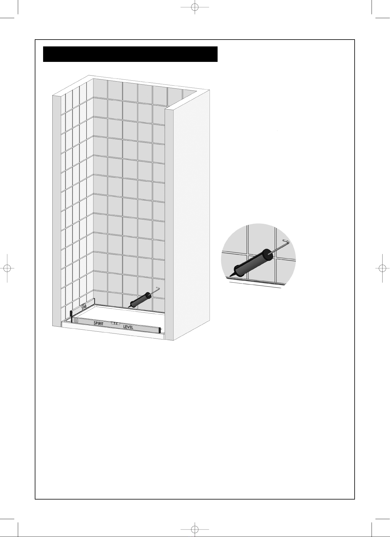
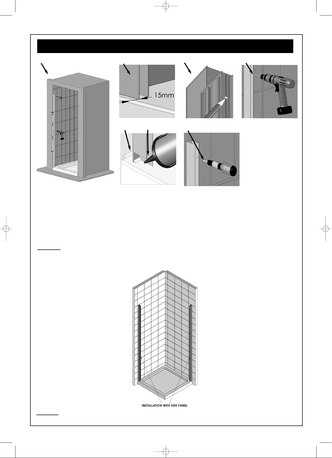
ALIGNMENT ON THE 2. Check that the wall profiles have been fitted 15mm in from the front outside edge of the tray Steps
TRAY OR FLOOR 2 & 3.
3. Check that the wall profiles have been fitted completely vertical (the bubble must be in the centre of
the two lines on a spirit level) Steps 2 & 3.
4. Check that the enclosure is completely vertical and level.
DOOR NOT 1. Check that the tray is completely level (the bubble must be in the centre of the two lines on a spirit
OPERATING / level), this could have an effect on the positioning of the door when adjusted, you might not have
CLOSING enough adjustment within the wall profile due to compensating for an out of level tray Step 1.
CORRECTLY 2. Check that the wall profiles are completely vertical (the bubble must be in the centre of the two
lines on a spirit level) Steps 2 & 3.
3. Check that the channels which the doors slide in has got some silicon lubrication gel in. (If not,
please apply some form of lubrication agent in the channels).
4. If the door does not hang vertically, you have further adjustment at the top of each wheel assembly.
Using the Allen key (supplied) turn the adjustment screw. Turning the adjustment screw clockwise
will lift the door, and turning the adjustment screw anti clockwise will lower the door Step 6.
ET Sliding Door:CSP 4/5/10 11:33 Page 10
This manual suits for next models
2
Table of contents
Other Ro-Man Bathroom Fixture manuals

Ro-Man
Ro-Man N2F7613S User manual

Ro-Man
Ro-Man SNWC User manual

Ro-Man
Ro-Man V8BV13 User manual

Ro-Man
Ro-Man KL Series User manual

Ro-Man
Ro-Man H2D6CS User manual

Ro-Man
Ro-Man KLBV User manual

Ro-Man
Ro-Man CQB User manual

Ro-Man
Ro-Man Haven6 H3P User manual

Ro-Man
Ro-Man DXL1HDR User manual

Ro-Man
Ro-Man Neo Angle DXP User manual
Popular Bathroom Fixture manuals by other brands

VIGO
VIGO VG06046 installation guide

METHVEN
METHVEN RERE 16-1027 installation guide

Signature Hardware
Signature Hardware CARMEN 928028 quick start guide

Costway
Costway OP3553 user manual

Signature Hardware
Signature Hardware 948956 Install

Fontana Showers
Fontana Showers BRAVAT FS1065 installation instructions