manuals.online logo
Brands
  1. Home
  2. •
  3. Brands
  4. •
  5. ROBBE
  6. •
  7. Toy
  8. •
  9. ROBBE Geier ARF User manual

ROBBE Geier ARF User manual

Montage- und Bedienungsanleitung
Assembly and operating instructions
Notice de montage et d´utilisation
Geier ARF
No. 3014
Geier ARF
2
Bauanleitung, Assembly instructions, Notice de montage
3014
No.
Lesen Sie vor Inbetriebnahme unbedingt diese Anleitung
und besonders unsere Sicherheitshinweise genau durch.
Wenn Sie ferngesteuerte Modellflugzeuge erstmalig
betreiben, empfehlen wir Ihnen, einen erfahrenen
Modellpiloten um Hilfe zu bitten.
Sicherheitshinweise
Ferngesteuerte Modelle sind kein Spielzeug im üblichen Sinne
und dürfen von Jugendlichen unter 14 Jahren nur unter
Aufsicht von Erwachsenen eingesetzt und betrieben werden.
Ihr Bau und Betrieb erfordert technisches Verständnis, hand-
werkliche Sorgfalt und sicherheitsbewusstes Verhalten.
Fehler oder Nachlässigkeiten beim Bau oder beim Fliegen
können erhebliche Sach- oder Personenschäden zur Folge
haben.
Da Hersteller und Verkäufer keinen Einfluss auf den ord-
nungsgemäßen Bau und Betrieb der Modelle haben, wird aus-
drücklich auf diese Gefahren hingewiesen und jegliche
Haftung ausgeschlossen.
Luftschrauben (Propeller) und generell alle sich drehenden
Teile, die durch einen Motor angetrieben werden, stellen eine
ständige Verletzungsgefahr dar.
Vermeiden Sie unbedingt eine Berührung solcher Teile.
Eine schnell drehende Luftschraube kann z.B. einen
Finger abschlagen!
Niemals im Gefährdungsbereich von Luftschrauben oder rotie-
renden Teilen aufhalten.
Achten Sie ebenfalls darauf, dass keine sonstigen
Gegenstände mit sich drehenden Teilen in Berührung kom-
men!
Schützen Sie Ihre Fernsteueranlage vor Staub, Schmutz und
Feuchtigkeit.
Setzen Sie die Geräte keiner übermäßigen Hitze, Kälte oder
Vibrationen aus.
Der Fernsteuerbetrieb darf nur im angegebenen
Temperaturbereich durchgeführt werden.
Benutzen Sie nur empfohlene Ladegeräte und laden Sie Ihre
Akkus nur bis zur angegebenen Ladezeit.
Be sure to read right through these instructions. This applies
in particular to the safety notes.
If you are new to radio-controlled model airplanes, we
recommend that you ask an experienced modeller for
help.
Safety notes
Radio-controlled models are not toys or playthings in the usual
meaning of the term, and they should only be operated by
young people under 14 years if an experienced adult is availa-
ble to supervise them.
Building and operating these models requires technical exper-
tise, manual skills, a careful attitude and safety-conscious
behaviour.
Errors, negligence and omissions in building or using these
models can result in serious personal injury and damage to
property.
The manufacturer and vendor of the equipment have no
means of checking that the models are built and operated cor-
rectly, and for this reason we can do no more than expressly
bring these hazards to your attention. We deny all further liabi-
lity.
Any rotating object which is driven by a motor represents a
constant hazard and a potential source of injury.
Avoid touching such parts at all costs. It is sobering to
think that a propeller turning at high speed could cut off
your finger.
Never stand in or close to the primary danger area of rotating
parts.
Take care to keep all other objects from making contact with
revolving parts.
Protect your radio control system from dust, dirt and damp.
Do not subject your equipment to excessive heat or cold.
Radio control systems should only be used in "normal" condi-
tions, i.e. within a normal temperature range.
Use recommended battery chargers only, and do not charge
your batteries for longer than the stated periods.
Lire attentivement la présente notice et en particulier nos
consignes de sécurité, avec précision.
Lorsque vous mettez en œuvre pour la première fois un
modèle d’avion, nous vous recommandons de vous faire
assister par un pilote chevronné.
Consignes de sécurité
Les modèles réduits ne sont pas des jouets dans le sens com-
mun du terme et doivent pas être mis en œuvre par des jeunes
gens de moins de 14 ans sans la surveillance d’adultes.
La construction et l’application des modèles réduits exigent cer-
taines connaissances, un soin manuel et un comportement
conscient des éventuels dangers.
Les erreurs ou les inattentions lors de la construction lors de la
construction ou de la mise en œuvre peuvent provoquer des
dommages importants tant au point de vue personnel que
matériel.
Étant donné que le constructeur et le distributeur n’ont aucune
incidence sur l’exploitation des modèles, ces dangers sont
expressément signalés et leur responsabilité exclue.
En règle générale, tous les éléments en rotation entraînés par
un moteur représentent un danger de blessure.
Éviter absolument le contact avec ces éléments. Une héli-
ce tournant rapidement est susceptible d’arracher un
doigt!
Eviter absolument d’entrer dans le secteur dangereux des élé-
ments en rotation.
Veiller également à éviter tout contact avec les composants
reliés à des éléments en rotation !
Protéger l’ensemble de radiocommande de la poussière, des
projections et de l’humidité.
Ne pas exposer l’appareil à une chaleur excessive ou au froid.
Le pilotage de modèle radiocommandés ne doit intervenir qu’à
des températures normales.
N’utiliser que les appareils de charge recommandés et ne
chargez vos accus que dans les délais indiqués.
Geier ARF
3
Bauanleitung, Assembly instructions, Notice de montage
3014
No.
Beachten Sie die Hinweise der Akkuhersteller.
Über- oder Falschladungen können zur Explosion der Akkus
führen. Achten Sie auf richtige Polung.
Überprüfen Sie Ihre Fernsteueranlage stets auf
Beschädigungen an Gehäusen und Kabeln.
Durch Absturz beschädigte oder nass gewordene Geräte,
selbst wenn sie wieder trocken sind, nicht mehr verwenden!
Entweder im robbe Service überprüfen lassen oder ersetzen.
Durch Nässe oder Absturz können versteckte Fehler entste-
hen, welche nach kurzer Betriebszeit zu einem
Funktionsausfall führen.
Es dürfen nur die von uns empfohlenen Komponenten und
Zubehörteile eingesetzt werden.
Verwenden Sie immer original robbe - Futaba
Steckverbindungen sowie original robbe-Futaba Steckquarze.
An den Anlagen dürfen keinerlei Veränderungen vorgenom-
men werden.
Routineprüfungen vor dem Start
Befinden sich mehrere Modellsportler am Platz, vergewissern
Sie sich vorher, dass Sie allein auf Ihrem Kanal senden, ehe
Sie Ihren Sender einschalten.
• Die Senderantenne immer ganz ausziehen und auf festen
Sitz prüfen.
• Immer zuerst den Sender, dann den Empfänger ein-
schalten.
• Immer zuerst den Empfänger, dann den Sender aus-
schalten.
• Führen Sie vor dem Start einen Reichweitentest durch.
• Ist der richtige Modellspeicher ausgewählt?
• Führen Sie einen Funktionstest durch. Prüfen Sie die
Laufrichtung und die Ausschläge der Ruder am Modell.
• Sind Mischfunktionen und Schalter richtig eingestellt?
• Ist der Ladezustand der Akkus ausreichend?
• Im Zweifel Modell niemals starten!
Modellbetrieb
• Überfliegen Sie niemals Zuschauer oder andere Piloten.
• Gefährden Sie niemals Menschen oder Tiere.
Read and observe the information supplied by the battery manu-
facturer.
Overcharging or incorrect charging methods can cause batte-
ries to explode.
Maintain correct polarity at all times.
Check your system regularly for damage to cases and wiring.
If a unit gets wet, it should not be used again even after you
have dried it out thoroughly.
The only safe course of action is to replace damaged equip-
ment, or at least have it checked by a robbe Service Centre.
Faults caused by damp may not be obvious to the layman, but
after a short period of further use they may cause terminal fai-
lure.
Please use only the components and accessories which we
expressly recommend.
Always use genuine robbe-Futaba connectors and original
robbe-Futaba plug-in crystals.
It is not permissible to make modifications of any kind to the
system components.
Routine pre-flight checks
If there are several modellers at your site, ensure that yours is
the only transmitter on "your" frequency before you switch on
your transmitter.
• Always extend the transmitter aerial fully before operating
your model, and check that it is firmly screwed into its
socket.
• Always switch on the transmitter first, then the receiver.
• Always switch off the receiver first, then the transmit-
ter.
• Carry out a range check before the flight or run.
• Have you selected the correct model memory?
• Check all the working systems. Ensure that the control sur-
faces respond to the stick commands in the correct "sense"
(right stick = right rudder etc.), and that the travels are as
recommended.
• Are all the mixer functions and switches set correctly?
• Are the batteries sufficiently charged?
• If you are not sure of any point - don’t fly!
Operating the model
• Never fly above spectators or other pilots.
• Do not fly in any way which could endanger humans or ani-
mals.
Tenir compte des indications fournies par le fabricant des
accus.
Les surcharges ou les charges mal réalisées sont susceptibles
de provoquer l’explosion des accus. Veiller à respecter les
polarités.
Contrôler systématiquement l’ensemble au niveau des dom-
mages éventuels du boîtier ou des cordons de connexion.
Ne plus utiliser les appareils endommagés ou mouillés même
s’ils ont été parfaitement séchés !
Les faire contrôler par les services techniques de robbe ou les
remplacer.
L’humidité est susceptible de provoquer des vices cachés en
mesure de provoquer une panne de fonctionnement après une
remise en œuvre brève.
N’utiliser que les composants électriques et les accessoires
que nous recommandons.
Utiliser systématiquement des connecteurs de marque robbe-
Futaba et des quartz originels robbe-Futaba.
N’effectuer aucune modification au niveau de l’ensemble de
radiocommande.
Contrôles de routine avant le démarrage ou le décollage
Si plusieurs modélistes opèrent sur la piste, s’assurer que le
canal utilisé est le seul avant de mettre l’ensemble de radio-
commande en marche.
• Tirer toujours systématiquement l’antenne de l’émetteur à
fond et en contrôler l’assise.
• Mettre toujours d’abord l’émetteur puis le récepteur en
marche.
• Couper toujours d’abord le récepteur avant l’émetteur.
• Avant de décoller ou de démarrer effectuer un essai de por-
tée.
• Avez-vous sélectionné la mémoire de modèle correcte ?
• Effectuer un essai des fonctions. Vérifier le sens du débat-
tement des gouvernes et leur course sur le modèle.
• Les fonctions de mixage et les commutateurs sont-ils cor-
rectement réglés ?
• La charge des accus est-elle suffisante ?
• En présence d’un doute ne jamais lancer le modèle !
Mise en œuvre du modèle
• Ne jamais survoler des spectateurs ou d’autres pilotes.
• Ne jamais mettre des personnes ou des animaux en danger.
Geier ARF
4
Bauanleitung, Assembly instructions, Notice de montage
3014
No.
• Fliegen Sie nie in der Nähe von Hochspannungsleitungen
oder Wohngebieten.
• Betreiben Sie Ihr Modell nicht auf öffentlichen Straßen,
Autobahnen, Wegen und Plätzen etc.
Bei Gewitter dürfen Sie Ihre Anlage nicht betreiben.
Im Betrieb nicht mit der Senderantenne auf das Modell ‘zielen’.
In dieser Richtung hat der Sender die geringste Abstrahlung.
Am Besten ist die seitliche Stellung der Antenne zum Modell.
Bei gleichzeitigem Betrieb von Fernsteuerungsanlagen auf
benachbarten Kanälen sollten die Piloten in einer losen
Gruppe beieinander stehen.
Abseits stehende Piloten gefährden sowohl das eigene Modell
als auch die Modelle der anderen Piloten.
Versicherung
Segelflugmodelle ohne Antriebsmotor sind üblicherweise in
einer Privathaftpflichtversicherung mitversichert.
Für Motorflugmodelle ist eine Zusatzversicherung oder
Erweiterung erforderlich.
Überprüfen Sie Ihre Versicherungspolice und schließen sie
ggf. eine Versicherung ab.
Haftungsausschluss:
Sowohl die Einhaltung der Montage- und Betriebsanleitung als
auch die Bedingungen und Methoden bei Installation, Betrieb,
Verwendung und Wartung der Fernsteuerkomponenten kön-
nen von robbe-Modellsport nicht überwacht werden.
Daher übernehmen wir keinerlei Haftung für Verluste, Schäden
oder Kosten, die sich aus fehlerhafter Verwendung und Betrieb
ergeben oder in irgendeiner Weise damit zusammenhängen.
Soweit gesetzlich zulässig ist die Verpflichtung zur
Schadenersatzleistung, gleich aus welchen Rechtsgründen,
auf den Rechnungswert der an dem schadensstiftenden
Ereignis unmittelbar beteiligten robbe-Produkten begrenzt.
Dies gilt nicht, soweit nach zwingenden gesetzlichen
Vorschriften wegen Vorsatzes oder grober Fahrlässigkeit
unbeschränkt gehaftet werden muss.
• Never fly close to high-tension overhead cables or residenti-
al areas.
• You must not operate your model from public roads, motor-
ways, paths, squares etc.
Never operate your equipment in stormy weather.
Don’t "point" the transmitter aerial straight at the model when
flying.
The signal generated by the transmitter is at its weakest in an
imaginary line extending from the aerial. It is always best if the
long side of the aerial points towards the model.
If several radio control systems are in use at the same time on
adjacent channels, the pilots should always stand together in
a loose group.
Pilots who insist on standing away from the group endanger
their own model as well as those of other pilots.
Insurance
Model gliders (unpowered models) are usually covered by
standard personal third-party insurance policies.
To fly powered model aircraft you will need to extend the cover
of your existing policy, or take out a specific policy.
Check your insurance policy and take out a new one if neces-
sary.
Liability exclusion
robbe Modellsport are not in a position to influence the way
you install, operate and maintain the radio control system com-
ponents.
For this reason we are obliged to deny all liability for loss,
damage or costs which are incurred due to the incompetent or
incorrect use and operation of our products, or which are
connected with such operation in any way.
Unless otherwise prescribed by law, the obligation of the com-
pany to pay compensation is limited to the invoice value of the
robbe products which were immediately and directly involved
in the event which caused the damage.
This does not apply if robbe is found to be subject to unlimited
liability according to binding legal regulation on account of deli-
berate or gross negligence.
• Ne jamais voler dans le voisinage de lignes à haute tension
ou de zones habitées.
• Ne faites jamais voler vos modèles sur des routes, des
autoroutes, des chemins ou des places.
En présence d’un orage ne mettez jamais votre ensemble de
radiocommande en marche.
Au cours de la séance de pilotage, ne pas « viser » le modèle
avec la pointe de l’antenne.
C’est dans cette direction que l’émetteur présente le rayonne-
ment le plus faible. La meilleure position de l’antenne est latéra-
le par rapport au modèle.
Si plusieurs modèles sont mis en œuvre simultanément avec
des ensembles de radiocommande dont les canaux de trans-
mission sont limitrophes, les pilotes constitueront un groupe
éparpillé.
Les pilotes se trouvant trop éloignés représentent un danger
pour son propre modèle et pour les modèles des autres.
Assurance
Les planeurs sans moteur sont généralement couverts par la
responsabilité civile.
Pour les modèles à moteur il faut généralement une police
d’assurance complémentaire ou étendue.
Contrôlez les garanties de votre police d’assurance et, si
nécessaire, souscrivez une assurance spécifique.
Exonération de la responsabilité
Le respect des indications de montage et de mise en œuvre de
même que les conditions et les méthodes d’installation, d’ex-
ploitation, d’application et de maintenance des composants de
l’ensemble de radiocommande ne peuvent être surveillées par
robbe Modellsport.
C’est pourquoi nous ne prenons aucune responsabilité en ce
qui concerne les pertes, dommages ou frais occasionnés par
une exploitation ou une mise en œuvre indues ou les domma-
ges consécutifs.
Pour autant qu’il est légalement permis, le devoir de réparation,
quels que soient les motifs légaux, est limité pour les produits
robbe à leur participation immédiate à la valeur calculée de
l’événement à l’origine du dommage.
Cette clauses ne s’applique pas lorsque la responsabilité est
évidente du point de vue des prescriptions contraignantes léga-
les en présence d’un dessein ou à cause d’une négligence évi-
dente.
Geier ARF
5
Bauanleitung, Assembly instructions, Notice de montage
3014
No.
Technische Daten
Spannweite: ca. 1500 mm
Flächeninhalt: ca. 44,5 dm
2
Fluggewicht (Segler): ab 910 g
Flächenbelastung (Segler): ab 20,45 g/dm
2
Nicht enthaltenes, jedoch erforderliches Zubehör siehe
Beilageblatt
Werkzeuge und Hilfsmittel siehe robbe Hauptkatalog
Allgemeine Hinweise für den Bauablauf
Die Numerierung entspricht im wesentlichen der Reihenfolge
des Bauablaufs der einzelnen Baustufe, wobei die Nummer vor
dem Punkt die Baustufe, die Nummer hinter dem Punkt das
betreffende Bauteil angibt.
Verschaffen Sie sich in Verbindung mit den Abbildungen und
den dazugehörigen Kurztexten sowie den Stücklisten einen
Überblick über die jeweiligen Bauschritte.
Hinweis: Es kann vorkommen, daß bestimmte Arbeitsschritte
wie Entfernen von Bespannfolie an Klebestellen etc. bereits
ausgeführt sind. diese Schritte in dem Fall überspringen.
Die Verarbeitungsvorschriften der einzelnen Klebstoffherstel-
ler beachten. Alle Klebestellen gut aushärten lassen.
Richtungsangaben wie z. B. „rechts“ sind in Flugrichtung
zu sehen.
Hinweis zur Stückliste: n.e. = nicht enthalten
Hinweise zur Fernsteueranlage
Orientieren Sie sich vor Baubeginn über die Einbaumöglich-
keit der zu verwendenden Fernsteueranlage.
Sollte eine andere, als die von uns vorgeschlagene
Fernsteuerung verwendet werden, so können Sie sich nach
dem Einbauschema richten. Maßdifferenzen sind allerdings
von Ihnen selbst auszugleichen.
Vor Baubeginn die Servos mit der Fernsteuerung in
Neutralstellung bringen (Knüppel und Trimmhebel am Sender
in Mittelstellung).
Caractéristiques techniques
Envergure: approx. 1500 mm
Surface alaire totale: approx. 44,5 dm
2
Poids en ordre de vol (planeur): à partir de 910 g
Charge alaire (planeur): à partir de 20,45 g/dm
2
Accessoires non contenus dans la boîte de construction
mais indispensables à la construction ou à la mise en
œuvre du modèle, cf. feuillet joint
Outillage et accessoires de montage, cf. catalogue général
robbe
Consignes générales concernant le montage
La numérotation des pièces correspond en règle générale à
leur ordre d’intervention dans la construction, le nombre devant
le point désignant le stade de montage concerné et le nombre
après le point, la pièce elle-même.
Lire attentivement la notice de construction au regard des listes
de pièces afin de se faire une vue d’ensemble du montage et
de ses diverses étapes.
À noter : il peut se produire que des opérations décrites dans
la notice, telles que le retrait du film d’entoilage à certains
endroits, soient déjà effectuées, dans ce cas, sauter la descrip-
tion concernée.
Tenir compte des prescriptions de fabricants des diverses
colles recommandées. Bien laisser durcir les points de collage.
Les données directionnelles comme gauche et droite
se rapportent au sens du vol.
Remarque concernant la liste des pièces
n.c. = non contenu
Recommandations concernant la radiocommande
Avant d’entreprendre la construction du modèle, il faut être en
possession de l’ensemble de radiocommande.
Si vous installez un autre ensemble de radiocommande que
celui que nous suggérons, rectifiez par vous-mêmes les
nuances de cotes.
Avant de les mettre en place, amener les servos au neutre à
l’aide de l’ensemble de radiocommande (manche et trim corre-
spondants en position médiane).
Specification
Wingspan: approx. 1500 mm
Total surface area: approx. 44.5 dm
2
All-up weight (glider): min. 910 g
Surface loading (glider): min. 20.45 g/dm
2
Please see separate sheet for details of essential items not
included in the kit.
The Robbe main catalogue includes information on a wide
range of tools and aids to building.
Sequence of assembly
In general terms the numbering of the parts corresponds to the
sequence of assembly; the number before the point indicates
the Stage of construction, the number after the point the indi-
vidual component.
Please study the instructions, the illustrations and the parts lists
before you start building, so that you have a clear idea before-
hand of how the model goes together.
Note: you may find that some stages of construction have
already been completed, e.g. removing covering film over joint
surfaces etc. In this case simply skip that stage.
Be sure to observe the guidelines provided by the manufactur-
ers of the various adhesives you use. Allow all glued joints to
harden fully before continuing with construction.
Directions such as „right-hand“ are as seen from the tail of
the model looking forward.
Notes on the parts list: N.I. = not included
Radio control equipment
Before you start building the model please check that your
receiving system will fit in the model as shown.
If you are using components other than the ones we recom-
mend you can still follow the basic arrangement shown, but you
may need to make allowance for minor differences in compo-
nent size.
Before you install the servos set them all to neutral from the
transmitter - sticks and trim levers central.
Geier ARF
6
Bauanleitung, Assembly instructions, Notice de montage
3014
No.
Hinweis zur Motordrossel: In Baustufe 5 wird der wahlweise
Einbau einer Motordrosselsteuerung beschrieben. Die erfor-
derlichen Teile sind nicht enthalten und müssen angefertigt
werden.
Hinweise zur Bespannung
Temparaturschwankungen während des Transports können zu
partiellem Verlust der Spannung der Bespannfolie führen.
Die Folie spannt sich wieder, wenn mit einem Föhn Wärme
zugeführt und die Folie glattgestrichen wird.
Der Bau des Modells
Baustufe 1, die Ruder
Nr. Bezeichnung, Maße in mm Stück
1.1 Scharnier 10 bei 1.2
1.2 Tragflächenhälfte je 1 re + li
1.3 Servo 2 n.e.
1.4 Kreuzhebel 2 bei 1.5
1.5 Klötzchen 4
1.6 Servodeckel je 1 re + li
1.7 Blechschraube Ø 2 x 12 8
1.8 Ruder je 1 re + li
1.9 Gabelkopf 2
1.10 Sicherungsring 2
1.11 Rudergestänge 2
1.12 Ruderhorn 2
1.13 Schraube M 2 x 15 4
1.14 Plättchen 2
1.15 Sicherungsclip 2
Indication concernant les gaz : au stade 5 est présentée la
mise en place facultative d’une commande des gaz du moteur.
Les éléments indispensables ne sont pas contenus dans la
boîte de construction et doivent être acquis ou réalisés par
ailleurs.
Attention: des variations de témperature au cours du transport
sont susceptibles de provoquer une perte partielle de tension
du film de l'entoilage. L'entoilage se retendra si vous le chauf-
fex avec un sèche-cheveux et le lissez.
La construction du modèle
Stade 1, les ailerons
N° désignation, cotes en mm nbre
1.1 charnière 10 avec 1.2
1.2 demi-aile 1 de ch., dr. + g.
1.3 servo 2 n.c.
1.4 palonnier en croix 2 avec 1.5
1.5 cales 4
1.6 couvercle de servo 1 de ch., dr. + g.
1.7 vis autotaraudeuse Ø 2 x 12 8
1.8 aileron 1 de ch., dr. + g.
1.9 chape 2
1.10 bague d’arrêt 2
1.11 tringle d’aileron 2
1.12 guignol 2
1.13 vis M 2 x 15 4
1.14 contre-plaque 2
1.15 clip de fixation 2
Note re. throttle: Stage 5 describes the installation of the
optional throttle control system. The parts required are not
included in the kit, and have to be made by the builder.
Notes regarding covering
Tempereture variations in transport may result in the covering
film losing some of its tautness.
The film will tightn up again if you warm it with a heat gun and
smooth it down.
Building the model
Stage 1, the elevons
No. Description, size in mm No. off
1.1 Hinge 10 With 1.2
1.2 Wing panel 2 R + L
1.3 Servo 2 N.I.
1.4 Cruciform output device 2 With 1.5
1.5 Servo mounting block 4
1.6 Servo well cover 2 R + L
1.7 Self-tapping screw Ø 2 x 12 8
1.8 Elevon 2 R + L
1.9 Clevis 2
1.10 Retaining ring 2
1.11 Pushrod 2
1.12 Horn 2
1.13 Screw M 2 x 15 4
1.14 Spreader plate 2
1.15 Pushrod keeper 2
- Scharniere 1.1 zur Hälfte mit Epoxy
einstreichen und in die Schlitze der
Tragflächenhälfte 1.2 einkleben -
Skizze „A“.
- Apply epoxy to one leaf of the hinges
1.1 and push them into the slots in the
wing panels 1.2 - fig. “A“.
- Enduire les charnières 1.1 à demi de la
colle époxy et les introduire dans les
fentes des demi-ailes 1.2 - fig „A“.
1.1
1.2
1
„A“
Geier ARF
7
Bauanleitung, Assembly instructions, Notice de montage
3014
No.
- Die Öffnungen an den Wurzelrippen
zum Durchziehen der Servokabel
freischneiden.
- Löcher für die Tragflächenschrauben
freilegen.
- Steuerscheiben der Servos 1.3 entfer-
nen. Servos mit der Fernsteuerung in
Neutralstellung bringen.
- Kreuzhebel 1.4 beschneiden, recht-
winklig zur Servolängsachse auf-
stecken und mit der
Servohebelschraube sichern.
- Beim zweiten Servo den Hebel spiegel-
bildlich montieren.
- Ein Ärmchen eines Kreuzhebels aufhe-
ben, da es zur Herstellung von Teil 3.4
benötigt wird.
- Servo mit Gummitüllen und Hülsen ver-
sehen.
- Die Klötzchen 1.5 nach Bohren der
Löcher mit Ø 1,5 mm am Servo ver-
schrauben.
- Schlitz für Ruderhebel auf dem
Servodeckel freilegen.
- Servo auf dem Servodeckel 1.6 aus-
richten. Der Arm des Kreuzhebels muß
zum Schlitz im Servodeckel fluchten. In
dieser Position die Klötzchen 1.5 am
Deckel 1.6 verkleben.
- Dégager les ouvertures des nervures
d’emplantures pour permettre le pas-
sage des cordons de servo.
- Dégager les trous des vis d’aile.
- Retirer le palonnier circulaire des ser-
vos 1.3. Amener les servos au neutre à
l’aide de l’ensemble de radiocom-
mande. Couper le palonnier en croix
1.4, comme indiqué ci-contre, le mettre
en place à angle droit par rapport à
l’axe longitudinal du servo et l’y fixer
avec la vis du servo.
- Sur le second servo d’aileron reprendre
la manœuvre en veillant à la symétrie.
- Conserver une branche du palonnier
en croix, elle servira ultérieurement à
réaliser la pièce 3.4.
- Munir les servos des passe-fils et des
manchons joints.
- Visser les cales 1.5 aux servos après
avoir percé les trous nécessaires avec
une mèche de Ø 1,5 mm..
- Dégager la fente pour le palonnier de
gouverne dans le couvercle du servo.
- Mettre les servos sur le couvercle de
servo 1.6. Le bras du palonnier en croix
doit se trouver en ligne avec l’entaille
dans le palonnier du servo. Dans cette
position coller les cales 1.5 au couver-
cle 1.6.
- Remove the covering film over
theopenings at the root ribs so that the
servo leads can be drawn through the
wings.
- Uncover the holes for the wing retainer
screws.
- Remove the output discs from the ser-
vos 1.3 and set the servos to neutral
from the transmitter.
- Cut down the cruciform output devices
1.4 as shown in the picture, fit them on
the servos at right-angles to the case
sides, and secure them with the servo
output screws.
- Note that the output arm of the second
servo must face in the opposite direc-
tion. Keep one spare arm cut from the
cruciform output device, as it is needed
to make part 3.4.
- Press the rubber grommets and tubular
spacers into the servo mounting lugs.
- Drill 1.5 mm Ø pilot-holes in the servo
mounting blocks 1.5 and screw the
blocks to the servos.
- Remove the covering film over the slot
for the servo output arm in the servo
well cover.
- Place the servo on the servo well cover
1.6. The output arm must line up cor-
rectly with the slot in the cover. Glue
the blocks 1.5 to the well cover 1.6 in
this position.
4
3
1.3
1.5
2
5
1.4
1.4
(3.4)
1.5
1.6
1.5 1.5
Geier ARF
8
Bauanleitung, Assembly instructions, Notice de montage
3014
No.
- Das Servokabel durch die Fläche zie-
hen.
- Servo mit Deckel einsetzen. Löcher mit
Ø 1,5 mm in den Ecken des Deckels
bohren und Deckel mit Schrauben 1.7
verschrauben.
- Die Ruder 1.8 unter Zugabe von wenig
Epoxy auf die Scharniere der
Tragflächenhälfte ansetzen. Auf
Leichtgängigkeit der Ruder achten.
- Gabelköpfe 1.9 mit Sicherungsringen
1.10 versehen, auf halbe
Gewindelänge auf die
Querrudergestänge 1.11 aufdrehen
und in den Servohebeln einhängen.
- Ruderhorn 1.12 fluchtend ausrichten
und Position des Ruderhorns auf dem
Ruder anzeichnen - Drehpunkt beach-
ten.
- Ruderhorn auf Ø 2 mm aufbohren.
- Löcher Ø 2 mm bohren und Ruderhorn
mit Schrauben 1.13 und Plättchen 1.14
befestigen.
- Überstehende Schraubenenden mit
einem Seitenschneider kürzen,
Schnittstellen planfeilen.
- Ruder in Neutralstellung (deckungs-
gleich zum Randbogen) bringen.
Gestänge über der Bohrung des
Ruderhorns markieren, abwinkeln und
kürzen.
- Gestänge mit Clips 1.15 versehen und
einhängen.
- Tirer le cordon du servo dans l’aile.
- Mettre le servo en place avec le cou-
vercle. Percer des trous de Ø 1,5 mm
dans les coins du couvercle et fixer le
couvercle à l’aide des vis 1.7.
- Installer les ailerons 1.8 avec un peu
de colle époxy sur les charnière. Veiller
à ce que les ailerons conservent leur
souplesse de rotation.
- Munir les chapes 1.9 des bagues d’ar-
rêt 1.10, les visser jusqu’à mi-filetage
sur la tringle d’aileron 1.11 et les
accrocher dans les palonniers des ser-
vos.
- Aligner le guignol 1.12 parfaitement au
centre et marquer la position du guignol
sur l’aileron - tenir compte de l’axe de
rotation.
- Percer le guignol avec une mèche de Ø
2 mm.
- Percer les trous de Ø 2 mm et fixer le
guignol avec les vis 1.13 et les contre-
plaques 1.14.
- Couper les extrémités excédentaires
des vis avec une pince coupante puis
limer l’arête de coupe.
- Amener l’aileron en position neutre
(parfaitement en ligne avec les bords
marginaux). Marquer la tringle au-
dessous de l’alésage du guignol, cintr-
er et raccourcir.
- Munir la tringle de clips et l’accrocher.
- Pull the servo lead through to the wing
root.
- Fit the servo and well cover in the wing,
and drill 1.5 mm Ø holes in the corners
of the cover. Fit the screws 1.7 to retain
the servo well cover. Repeat the proce-
dure with the second elevon servo.
- Apply a little epoxy to the hinges pro-
jecting from the wing trailing edge, and
push the elevons onto them. Keep the
hinge line gap narrow, but check that
the elevons move freely up and down.
- Push the retaining rings 1.10 onto the
clevises 1.9, screw them about half-
way onto the threaded elevon pushrods
1.11 and connect them to the servo out-
put arms.
- Position the horn 1.12 on the elevon,
exactly in line with the servo pushrod,
and mark its location on the elevon -
note the correct position of the linkage
holes relative to the hinge pivot line.
- Drill out the horn to 2 mm Ø.
- Drill 2 mm Ø holes in the elevon at the
marked points and fix the horn in place
using the screws 1.13 and spreader
plate 1.14.
- Cut off excess screw material using
side-cutters, and sand the cut ends flat.
- Set the elevon to neutral (in line with
the wingtip). Mark where the pushrod
crosses the horn hole, bend it at right-
angles and snip off the excess pushrod
material. Fit the keeper 1.15 on the
pushrod and connect it to the horn.
Repeat the whole procedure with the
second elevon.
1.7
7
6
9
1.6
1.8
1.9
1.10
1.11
1.12
1.13
1.14
1.12
1.13
1.15
1.12
Ø 2 mm
8
10
Geier ARF
9
Bauanleitung, Assembly instructions, Notice de montage
3014
No.
Baustufe 2, Zusammenbau der Tragfläche, Seitenleitwerke
Nr. Bezeichnung, Maße in mm Stück
2.1 Tragflächenverbinder 1
2.2 Mittelrippe, Segler 1
2.3 Mittelrippe, Motorsegler 1
2.4 Endleistenaufdopplung 1
2.5 Seitenleitwerk 2
Stade 2, assemblage des demi-ailes
N° désignation, cotes en mm nbre
2.1 élément de liaison des demi-ailes 1
2.2 nervure centrale, planeur 1
2.3 nervure centrale, motoplaneur 1
2.4 renfort de bord de fuite 1
2.5 dérive 2
Stage 2, joining the wing panels, installing the fins
No. Description, size in mm No. off
2.1 Wing joiner brace 1
2.2 Centre rib, glider 1
2.3 Centre rib, powered glider 1
2.4 Trailing edge doubler 1
2.5 Fin 2
- Tragflächenverbinder 2.1, falls erfor-
derlich, überschleifen.
- Reichlich Klebstoff in den Schacht der
rechten Flächenhälfte einträufeln.
Verbinder in die rechte Flächenhälfte
1.1 einkleben.
- Noch vor Aushärten des Klebstoffs die
ausgewählte Mittelrippe 2.2 oder 2.3
beidseitig mit Klebstoff einstreichen
und aufsetzen.
- Sand the joiner brace 2.1 if necessary
to obtain a close fit in the wing sockets.
- Apply plenty of epoxy to the inside of
the brace socket in the right-hand wing
panel, and push the joiner brace 2.1
into the socket.
- While the glue is stiff soft, apply epoxy
to both sides of the centre rib 2.2 or 2.3
and press it against the wing root.
- Si nécessaire, poncer le raccord d’aile
2.1.
- Introduire un bon bourrelet de colle
dans le compartiment de la demi-aile
droite. Coller le raccord dans la demi-
aile droite 1.1.
- Avant que la colle soit sèche, enduire
la nervure centrale 2.2 ou 2.3 de colle
et la mettre en place.
2.1
2.2
- Hinweise: Dem Montagekasten liegen zwei Mittelrippen 2.2
und 2.3 bei. Wenn das Modell als reiner Segler gebaut wer-
den soll, die Mittelrippe 2.2 verwenden. Bei vorgesehenem
Hilfsmotor die Mittelrippe 2.3 einbauen.
- In den folgenden Darstellungen (Baustufen 1 bis 3) ist das
Modell mit Mittelrippe 2.2 gezeigt.
- Es wird mit Epoxy geklebt.
- Das Verkleben von Flächenhälften, Verbinder und Mittelrippe
muß in einem Arbeitsgang erfolgen.
- Notes: the kit includes two different centre ribs 2.2 and 2.3.
If the model is to be built as a pure glider, use the centre rib
2.2. If you intend fitting an auxiliary motor, install the centre
rib 2.3.
- The pictures in Stages 1 to 3 show the model with the centre
rib 2.2.
- Use epoxy for this stage.
- The wing panels, joiner brace and centre rib must be glued
together in a single process.
- À noter : dans la boîte de construction se trouvent deux
nervures centrales différentes, 2.2 et 2.3. Lorsque le modèle
est réalisé sous forme d’un planeur pur, utiliser la nervure
centrale 2.2. Lorsqu’il est prévu de construire le modèle avec
un moteur auxiliaire, utiliser la nervure centrale 2.3.
- Sur les fig. ci-dessous, le modèle est représenté avec la
nervure centrale 2.2 (stades de montage 1 à 3).
- effectuer les collages à l’aide de colle époxy.
- L’encollage des demi-ailes, du raccord et de la nervure cen-
trale doit être réalisé en une seule opération.
11
1.1
12
Geier ARF
10
Bauanleitung, Assembly instructions, Notice de montage
3014
No.
- Reichlich Klebstoff in den Schacht der
linken Flächenhälfte träufeln und
Flächenhälfte ansetzen. Darauf ach-
ten, daß die Hälften nicht gegeneinan-
der verwunden sind und die
Wurzelrippen spaltfrei an der
Mittelrippe anliegen.
- Übergequollenen Klebstoff sofort
abstreichen.
- Die Folie an den Klebestellen von
Endleiste und Endleistenaufdopplung
2.4 entfernen, Aufdopplung aufkleben
und bis zum Aushärten des Klebstoffs
mit Klammern fixieren.
- Jeweils an der dritten Tragflächenrippe
von außen befindet sich eine
Doppelrippe, um einen Schacht für die
Seitenleitwerke 2.5 zu bilden. Die Folie
nur auf der Oberseite der Tragfläche
über dem Schacht entfernen.
- Klebefläche des Seitenleitwerks mit
Weißleim oder Epoxy einstreichen.
- Seitenleitwerke 2.5 einsetzen, recht-
winklig zur Tragfläche ausrichten.
Klebstoff aushärten lassen.
- Introduire un bon bourrelet de colle
dans le compartiment de la demi-aile
gauche et mettre l’aile gauche en
place. Veiller à ce que les demi-ailes ne
présentent pas de gauchissement l’une
par rapport à l’autre et que les nervures
d’emplanture coïncident parfaitement
avec la nervure centrale.
- Retirer immédiatement la colle excé-
dentaire.
- Retirer le film d’entoilage au niveau des
emplacements de collage des bords de
fuite et des renforts de bord de fuite
2.4, coller les renforts et les fixer avec
des pinces à linge jusqu’à ce que la
colle soit sèche.
- Sur la troisième nervure de chacune
des demi-ailes en partant de l’extérieur
se trouve une nervure double pour con-
stituer le logement des dérives 2.5.
Retirer le film d’entoilage de l’extrados
de l’aile au-dessus de ce logement.
- Enduire la surface d’encollage des
dérives de colle cellulosique ou de colle
époxy.
- Mettre les dérives 2.5 en place, les
ajuster à angle droit par rapport à l’aile.
Laisser la colle durcir.
- Apply plenty of epoxy to the inside of
the brace socket in the left-hand wing
panel, and push this panel onto the
joiner brace and against the centre rib
and first wing panel. Ensure that the
panels are not twisted relative to each
other, and that the root ribs butt up
accurately against the centre rib, with-
out any gaps.
- Wipe off excess epoxy immediately.
- Remove the covering film over the joint
surfaces at the root trailing edge and
the trailing edge doubler 2.4. Glue the
doubler to the wing, and clamp it in
place while the glue is hardening.
- At the third wing rib from the tip on each
side you will find a double rib; these
ribs form slots for the fins 2.5. Remove
the covering film over the slot on the
top surface of the wing only.
- Apply white glue or epoxy to the joint
surface on both sides of the fins.
- Slide the fins 2.5 into the slots, set
them at right-angles to the wing, and
allow the glue to cure fully.
2.4
2.5
2.8
14
13
15
16
Geier ARF
11
Bauanleitung, Assembly instructions, Notice de montage
3014
No.
Baustufe 3, Rumpfboot und RC-Einbau
Nr. Bezeichnung, Maße in mm Stück
3.1 Schalterkabel 1 n.e.
3.2 Rumpfboot 1
3.3 Empfänger 1 n.e.
3.4 Zugentlastung 1 bei 1.6
3.5 Power-Pack 1 n.e.
3.6 Kunststoffschraube 2 Kreuzschl.
3.7 Haube 1
3.8 Blechschraube Ø 2 x 12 1
3.9 Halteklötzchen 1
3.10 Hochstarthaken 1
- Bei Bedarf den Schalter 3.1 in der lin-
ken Rumpfseitenwand des
Rumpfboots 3.2 einbauen.
- Alternativ kann der Schalter mittels
Doppelklebeband im Innern des
Rumpfs angebracht werden.
- Die Litzenantenne des Empfängers 3.3
abwickeln.
- Aus einem abgetrennten Ärmchen
eines Kreuzhebels die Zugentlastung
3.4 herstellen und auf die
Litzenantenne fädeln.
- Den Empfänger 3.3 und den Power-
Pack 3.5 einlegen und am
Schalterkabel anschließen.
- Die Servos am Seitenruder- und
Höhenruderkanal des Empfängers
anschließen.
3.1
Stade 3, fuselage et ensemble de réception
N° désignation, cotes en mm nbre
3.1 cordon-interrupteur 1 n.c.
3.2 cellule du fuselage 1
3.3 récepteur 1 n.c.
3.4 dispositif de décharge 1 avec 1.6
3.5 alimentation du récepteur 1 n.c.
3.6 vis en plastique 1 tête croisée
3.7 verrière 1
3.8 vis autotaraudeuse Ø 2 x 12 1
3.9 cales de maintien 1
3.10 crochet de remorquage 1
- Installer le cordon interrupteur 3.1 dans
la paroi latérale gauche de la cellule du
fuselage 3.2.
- Il est également possible d’installer
alternativement le cordon-interrupteur
avec un morceau d’adhésif double face
à l’intérieur du fuselage.
- Développer l’antenne souple du récep-
teur 3.3.
- À partir d’une des branches coupée
d’un palonnier réaliser le dispositif de
décharge 3.4 et l’enfiler sur l’antenne
souple du récepteur.
- Mettre le récepteur 3.3 et son alimenta-
tion 3.5 en place et raccorder au cor-
don-interrupteur.
- Raccorder les servos aux voies corre-
spondantes du récepteur.
Stage 3, fuselage pod and RC installation
No. Description, size in mm No. off
3.1 Switch harness 1 N.I.
3.2 Fuselage pod 1
3.3 Receiver 1 N.I.
3.4 Strain relief 1 From 1.6
3.5 Receiver battery 1 N.I.
3.6 Plastic screw 2 Cross-point
3.7 Canopy 1
3.8 Self-tapping screw Ø 2 x 12 1
3.9 Towhook support block 1
3.10 Towhook 1
- Install the switch 3.1 in the left-hand
side of the fuselage pod 3.2.
- Alternatively the switch can be mount-
ed inside the fuselage using double-
sided tape.
- Unwind the flexible aerial attached to
the receiver 3.3.
- Cut the strain relief 3.4 to shape from a
spare output device arm, and thread it
onto the aerial.
- Place the receiver 3.3 and the receiver
battery 3.5 in the pod, and connect
them to the switch harness.
- Connect the servos to the rudder and
elevator sockets at the receiver.
3.5
17
18 3.3
3.4
3.3
3.2
19
Geier ARF
12
Bauanleitung, Assembly instructions, Notice de montage
3014
No.
- Tragfläche aufsetzen und mit den
Kunststoffschrauben 3.6 montieren.
- Die Haube 3.7 aufsetzen, ausrichten
und Bohrung für die Schraube auf das
eingeklebte Holzklötzchen übertragen.
- Loch mit Ø 1,5 mm bohren, Haube mit
der Schraube 3.8 fixieren.
- Power-Pack und Empfänger werden
nach dem Auswiegen mit Schaum-
gummi umwickelt und rutschsicher und
vibrationsgedämpft endgültig im Rumpf
platziert. Alternativ kann zur
Befestigung von Empfänger und
Power-Pack Klettband verwendet wer-
den.
- Mettre l’aile en place et la fixer avec les
vis en plastique 3.6.
- Mettre la verrière 3.7 en place, l’ajuster
et reporter la position de l’alésage de la
vis sur la cale de maintien collée à
l’emplacement prévu.
- Percer un trou de Ø 1,5 mm, fixer la
verrière à l’aide de la vis 3.8.
- Une fois que le modèle a été équilibré,
envelopper le récepteur et son alimen-
tation dans de la mousse plastique et
les installer dans le fuselage à l’abri
des vibrations et en évitant qu’ils puis-
sent encore se déplacer. Il est égale-
ment possible d’utiliser des morceaux
de bande Velcro autoadhésive pour
fixer ces composants dans le fuselage.
- Place the wing on the fuselage pod and
fit the plastic screws 3.6 to secure it.
- Place the canopy 3.7 on the model,
align it carefully and mark the position
of the retaining screw on the wooden
block which is already glued in place.
- Drill a 1.5 mm Ø hole at the marked
point, and fit the screw 3.8 to secure
the canopy.
- Once you have balanced the model
accurately, pack the receiver battery
and receiver in foam rubber (for
shock/vibration absorption) and stow
them permanently in the fuselage.
Check that they are firmly located.
Velcro (hook-and-loop) tape is a good
alternative method of mounting the
receiver and receiver battery.
3.6
Ø 1,5 mm
20
21
22
3.7
Geier ARF
13
Bauanleitung, Assembly instructions, Notice de montage
3014
No.
- Ein Loch Ø 2 mm für die
Empfängerantenne im Rumpfheck
bohren
- Die Empfängerantenne kann wahlwei-
se als Schleppantenne geflogen, oder
an der Tragflächenunterseite verlegt
und mit einem Streifen Tesafilm gesi-
chert werden.
- In diesem Fall die Antenne beim
Demontieren des Modells von der
Tragfläche lösen.
- Nach Maßangabe ein Loch Ø 2 mm
mittig in den Rumpf bohren.
- Das Halteklötzchen 3.9 mit Epoxy über
der Bohrung mittig verkleben.
- Halteklötzchen mit Ø 2 mm vorbohren
und Hochstarthaken 3.10 eindrehen.
- Drill a 2 mm Ø hole for the receiver
aerial in the rear part of the fuselage
pod.
- The receiver aerial can be deployed
simply trailing out of the tail; alterna-
tively it can be run along the underside
of the wing and secured with a strip of
adhesive tape.
- In this case remember to disconnect
the aerial from the wing before dis-
mantling the model!
- Drill a central 2 mm Ø hole in the fuse-
lage at the stated position.
- Epoxy the towhook support block 3.9
centrally over the hole.
- Drill a 2 mm Ø pilot-hole in the support
block, and screw the towhook 3.10 into
it.
- Percer un trou de Ø 2 mm dans la
queue du fuselage pour permettre le
passage de l’antenne souple du récep-
teur.
- Il est possible de laisser pendre l’an-
tenne sous le modèle ou de l’agencer
sous l’aile en l’y collant avec des
morceaux de ruban adhésif.
- Dans ce dernier cas, lorsque vous
démontez le modèle, retirer d’abord de
l’aile les morceaux de ruban adhésif
qui maintiennent l’antenne.
- Selon les cotes indiquées, percer un
trou de Ø 2 mm dans le centre du fuse-
lage.
- Coller la cale de maintien 3.9 au cen-
tre de l’alésage avec de la colle époxy.
- Prépercer la cale de maintien avec une
mèche de Ø 2 mm et y visser le cro-
chet de remorquage 3.10.
23
24
25
26
Ø 2 mm
Ø 2 mm
3.9
3.10
65 mm
Geier ARF
14
Bauanleitung, Assembly instructions, Notice de montage
3014
No.
- Den Pylontank 4.1 gemäß beiliegender
Anleitung montieren. Die beigefügten
Holzteile werden nicht benötigt.
- Mittelrippe 2.3: Die Bespannfolie zwi-
schen den äußeren Rippen und über
den Bohrungen entfernen.
- Verbrennungsmotor 4.2 mit Schrauben
4.3, Scheiben 4.4 und Muttern 4.5 ein-
bauen.
- Den fertigen Hilfsmotoraufsatz einset-
zen und verschrauben.
- Installer le pylône-réservoir 4.1 selon
les indications fournies par la notice
jointe. Les éléments de bois joints sont
superflus.
- Nervure centrale 2.3 : retirer le film
d’entoilage entre les nervures
extérieures et au-dessus des alésages.
- Monter le moteur thermique 4.2 à l’aide
des vis 4.3, des rondelles 4.4 et des
écrous 4.5.
- Mettre le moteur auxiliaire avec support
en place et le visser.
- Assemble the pylon tank 4.1 as
described in the instructions supplied
with it. The wooden parts supplied in
the set are not required for this model.
- Centre rib 2.3: remove the covering
film between the outer ribs and over the
screw holes.
- Install the glow motor 4.2 using the
screws 4.3, washers 4.4 and nuts 4.5.
- Fit the completed auxiliary motor
assembly on the centre rib, and fix it in
place using the remaining screws, nuts
and washers.
4.1
4.2
Baustufe 4, der Hilfsmotor-Aufsatz
Nr. Bezeichnung, Maße in mm Stück
4.1 Pylontank 1 n.e.
4.2 Verbrennungsmotor 1 n.e.
4.3 Schraube M 3 x 25 6 n.e.
4.4 Scheibe Ø 3,2 6 n.e.
4.5 Mutter M 3 6 n.e.
4.6 Luftschraube 1 n.e.
4.7 Spinner 1 n.e.
4.8 Schalldämpfer 1 n.e.
Stage 4, auxiliary motor pylon
No. Description, size in mm No. off
4.1 Pylon tank 1 N.I.
4.2 Glowplug motor 1 N.I.
4.3 Screw M 3 x 25 6 N.I.
4.4 Washer 3.2 Ø 6 N.I.
4.5 Nut M 3 6 N.I.
4.6 Propeller 1 N.I.
4.7 Spinner 1 N.I.
4.8 Silencer 1 N.I.
Stade 4, aménagement du dispositif d’installation du
moteur auxiliaire
N° désignation, cotes en mm nbre
4.1 pylône-réservoir 1 n.c.
4.2 moteur thermique 1 n.c.
4.3 vis M 3 x 25 6 n.c.
4.4 rondelle Ø 3,2 6 n.c.
4.5 écrou M 3 6 n.c.
4.6 hélice 1 n.c.
4.7 cône d’hélice 1 n.c.
4.8 silencieux 1 n.c.
2.3
29
28
27
4.3 - 4.5
4.3 - 4.5
Geier ARF
15
Bauanleitung, Assembly instructions, Notice de montage
3014
No.
- Hinweis: Der Spinner 4.7 ist bei
Verwendung eines Elektro-Starters
erforderlich.
- Luftschraube 4.6 und Spinner 4.7
montieren. Falls erforderlich, die
Spinnerkappe an die Luftschraube
anpassen.
- Den Schalldämpfer 4.8 am Motor ver-
schrauben. Die Drossel des Vergasers
in Vollgasstellung bringen und mit der
Leerlauf-Anschlagschraube blockieren.
- Die Zugachse des Motors etwa parallel
zur Profilunterseite der Tragfläche ein-
stellen. Dies ist die Grundeinstellung.
Bei zu starkem oder zu schwachem
Steigflug die Motorzugachse in kleinen
Schritten entsprechend korrigieren.
- Hinweis: Einstellungen an den Rudern
sowie der Schwerpunkt ändern sich
durch die Montage des
Hilfsmotoraufsatzes nicht. Ein
Umstellen der Ruder oder erneutes
Auswiegen ist daher nicht erforderlich.
- Achtung: Die Empfängerantenne muß
so verlegt und gesichert sein, daß sie
während des Fluges nicht in den
Drehkreis der Luftschraube geraten
kann.
- À noter : le cône d’hélice 4.7 est indis-
pensable lorsqu’on utilise un démar-
reur à main électrique.
- Monter l’hélice 4.6 et le cône d’hélice
4.7. Si nécessaire, ajuster le capuchon
du cône d’hélice à l’hélice.
- Visser le silencieux 4.8 au moteur.
Amener le boisseau du carburateur en
position plein gaz et le bloquer avec la
vis de ralenti.
- Régler l’axe de traction du moteur pra-
tiquement parallèlement à la face
inférieure du profil de l’aile. Il s’agit d’un
réglage initial. Si le vol ascensionnel
s’avère trop faible ou trop raide, cor-
riger l’axe de traction du moteur en
conséquence en procédant par petites
étapes.
- À noter : les réglages des gouvernes
et le centre de gravité du modèle ne
sont pas modifiés par la mise en place
du moteur auxiliaire. Il n’est donc pas
nécessaire de revoir le réglage des
gouvernes ni de rééquilibrer le modèle.
- Attention : l’antenne souple du récep-
teur doit être disposée et aménagée de
manière que pendant le vol elle ne soit
pas en mesure d’entrer dans le plan de
rotation de l’hélice.
- Note: you must fit a spinner if you wish
to use an electric starter.
- Fit the propeller 4.6 and the spinner 4.7
on the motor. You may need to trim the
spinner cap to clear the propeller.
- Screw the silencer 4.8 to the motor.
Move the carburettor throttle arm to the
full-throttle setting, and adjust the idle
stop screw to fix it in that position.
- Set the thrustline of the motor roughly
parallel to the underside of the wing
section. This is the basic setting; if the
model climbs too steeply, or not steeply
enough, adjust the motor thrustline in
small increments until you are satisfied.
- Note: the elevon settings and the
Centre of Gravity are not affected by
installing the auxiliary motor pylon. It is
therefore not necessary to re-adjust the
elevons, or re-balance the model.
- Caution: the receiver aerial must be
deployed and secured in such a way
that there is no chance of it getting into
the rotational plane of the propeller.
30
31
4.7
4.6
4.8
3.8
32
Geier ARF
16
Bauanleitung, Assembly instructions, Notice de montage
3014
No.
- Haltewinkel 5.1 anfertigen. Gestänge
5.2 mit einer Z-Kröpfung versehen, in
das Führungsröhrchen 5.3 schieben
und im Drosselhebel einhängen.
- Haltewinkel auf das Röhrchen setzen,
Laschen umbiegen, Röhrchen mit
Epoxy fixieren. Haltewinkel mit der hin-
teren Motorschraube befestigen.
- Nach Maßangaben ein Loch Ø 2 mm
durch die Tragfläche bohren.
- Plättchen 5.4 auf das Röhrchen 5.3
schieben. Röhrchen durchstecken,
zweites Plättchen aufschieben. Teile
mit Sekundenkleber fixieren.
- Den Servorahmen 5.5 nach
Servogröße anfertigen, Klötzchen 5.6
und Halteleiste 5.7 aufkleben. Servo
5.8 einbauen. Kreuzhebel beschnei-
den. Servoeinheit so an die Mittelrippe
kleben, daß das Gestänge über dem
Kreuzhebel liegt. Führungsröhrchen
und Gestänge entsprechend kürzen.
- Ein kurzes Z-Gestänge 5.9 anfertigen
und im Kreuzhebel einhängen. Die
Gestänge mit dem Stellring 5.10 mit-
einander verbinden.
- Drossel ganz öffnen, Servo in
Vollgasstellung bringen, Schraube des
Stellrings anziehen.
- Réaliser l’équerre de maintien 5.1
- Munir la tringle 5.2 d’un cintrage en Z, la
glisser dans le tube-guide 5.3 et l’ac-
crocher dans le palonnier des gaz.
- Installer l’équerre de maintien sur le
tube, cintrer les éclisses, fixer le tube
avec de la colle époxy. Fixer l’équerre
de maintien à l’aide de la vis arrière du
moteur. Selon les cotes indiquées,
percer un trou de Ø 2 mm dans l’aile.
- Glisser une plaquette 5.4 sur le tube 5.3.
Enfiler le tube et y glisser la seconde
plaquette. Fixer les éléments avec de la
colle cyanoacrylate.
- Réaliser le châssis du servo 5.5 en fonc-
tion de l’encombrement du servo, coller
la cale 5.6 et la baguette de maintien
5.7. Monter le servo 5.8. Découper le
palonnier en croix comme indiqué.
Coller l’unité du servo sur la nervure
centrale de sorte que la tringle se trouve
au-dessus du palonnier. Raccourcir le
tube-guide et la tringle en conséquence.
- Réaliser une tringle courte en Z 5.9 et
l’accrocher dans le palonnier en croix.
Raccorder les tringles à l’aide de la
bague d’arrêt 5.10. Ouvrir complète-
ment le boisseau, amener le servo en
position plein gaz, serrer la vis sans tête
de la bague d’arrêt.
- Cut the bracket 5.1 to shape.
Form a Z-bend in one end of the
pushrod 5.2, slip it into the snake outer
5.3 and connect it to the throttle arm on
the motor.
- Place the bracket over the snake outer
and bend the lug round it. Epoxy the
tube to the bracket. The bracket is held
in place by the rear motor mounting
screw. Drill a 2 mm Ø hole through the
wing at the stated position.
- Slip one of the plates 5.4 onto the
snake outer 5.3, push the tube through
the hole in the wing and fit the second
plate on the other end. Fix the plates to
the wing with a drop of cyano.
- Cut the servo mounting frame 5.5 to
suit the size of the throttle servo you
wish to use. Glue the block 5.6 and the
retaining strip 5.7 on top, and install
the servo 5.8. Cut down the cruciform
output device as shown, and glue the
servo assembly to the centre rib with
the pushrod located over the output
arm. Shorten the snake outer and the
pushrod to suit. Make up the short
pushrod 5.9 and connect it to the servo
output arm. Connect the two pushrods
using the collet and screw 5.10.
- Open the throttle fully, set the servo to
the full-throttle position, and tighten the
screw in the collet.
33
34
35
36
Baustufe 5, die Motordrossel
Nr. Bezeichnung, Maße in mm Stück
5.1 Haltewinkel 1 n.e.
5.2 Gestänge, Ø 0,8 x 300 1 n.e.
5.3 Führungsröhrchen, Ø 2 x 180 1 n.e.
5.4 Plättchen Ø 15 x 1 2 n.e.
5.5 Servorahmen, 3 x 35 x 70 1 n.e.
5.6 Klötzchen, 10 x 10 x 35 1 n.e.
5.7 Halteleiste, 3 x 5 x 70 1 n.e.
5.8 Drosselservo 1 n.e.
5.9 Z-Gestänge, Ø 1,2 x 30 1 n.e.
5.10 Stellring mit Madenschraube 1 n.e.
Stage 5, throttle system
No. Description, size in mm No. off
5.1 Bracket 1 N.I.
5.2 Pushrod, 0.8 Ø x 300 1 N.I.
5.3 Snake outer, 2 Ø x 180 1 N.I.
5.4 Plate, 15 Ø x 1 2 N.I.
5.5 Servo mounting frame, 3 x 35 x 70 1 N.I.
5.6 Mounting block, 10 x 10 x 35 1 N.I.
5.7 Retaining strip, 3 x 5 x 70 1 N.I.
5.8 Throttle servo 1 N.I.
5.9 Pre-formed pushrod, 1.2 Ø x 30 1 N.I.
5.10 Collet and grubscrew 1 N.I.
Stade 5, la commande des gaz
N° désignation, cotes en mm nbre
5.1 équerre de maintien 1 n.c.
5.2 tringle, Ø 0,80 x 300 1 n.c.
5.3 tube-guide, Ø 2 x 180 1 n.c.
5.4 plaquette, Ø 15 x 1 2 n.c.
5.5 châssis du servo, 3 x 35 x 70 1 n.c.
5.6 cale, 10 x 10 x 35 1 n.c.
5.7 baguette de maintien, 3 x 5 x 70 1 n.c.
5.8 servo des gaz 1 n.c.
5.9 tringle en Z, Ø 1,2 x 30 1 n.c.
5.10 bague d’arrêt avec vis sans tête 1 n.c.
5.1 5.2
5.3
18 mm
60 mm
Ø 2 mm 5.4
5.5
5.6
5.7
5.8
5.9 5.10
5.1 5.4M 1:1
5.2
4.3
5.4
Geier ARF
17
Bauanleitung, Assembly instructions, Notice de montage
3014
No.
Auswiegen
- Das Modell komplett zusammenbau-
en. Den Schwerpunkt „C. G.“ beidsei-
tig am Rumpf anzeichnen.
- Das Modell mit den Zeigefingern im
Schwerpunkt unter den Tragflächen
nahe des Rumpfes unterstützen und
auspendeln lassen. Die Idealstellung
ist erreicht, wenn das Modell mit leicht
nach unten hängendem Vorderteil in
der Waage bleibt.
- Hängt die Flächenhinterkante nach
unten, Empfänger und Power-Pack
nach vorn verschieben. Wenn das
Rumpfvorderteil zu stark nach unten
hängt, Empfänger und Power-Pack
nach hinten schieben. Erst wenn dies
nicht ausreicht Trimmblei verwenden.
Erforderliches Trimmblei so fixieren,
daß es während des Fluges nicht ver-
rutschen und den Schwerpunkt verän-
dern kann.
Balancing
- Assemble the model completely, ready
to fly. Mark the balance point „CG“ on
both sides of the fuselage.
- Support the model close to the fuse-
lage at the marked points, resting it on
your two index fingers, and allow it to
hang freely. Ideally the model will bal-
ance level, with the nose inclined
slightly downward.
- If the tail hangs down the receiver and
the battery must be shifted forward. If
the nose hangs down too far, the
receiver and the battery should be
shifted aft. Only use lead ballast at the
last resort. Be sure to fix any lead
securely so that it cannot shift when
the model is in flight, as this would alter
the model’s balance.
Équilibrage
- Assembler complètement le modèle,
fixer l’aile au fuselage et marquer le
centre de gravité „C.G.“ de chaque
côté sur le fuselage.
- Maintenir le modèle avec les index
sous l’aile avec les index disposés
près du fuselage et le maintenir en
équilibre. Il est parfaitement équilibré
lorsqu’il reste en équilibre avec le nez
légèrement vers le bas.
- Si le bord de fuite penche trop vers le
bas, déplacer le récepteur et l’accu
vers l’avant. Si son nez penche trop
vers le bas, déplacer le récepteur et
l’accu vers l’arrière. Si cela ne suffit
pas, utiliser du plomb de lestage. Fixer
le plomb de lestage de manière qu’il ne
puisse se déplacer.
Funktionsprobe der Ruder
- Das Modell wird über die kombinierten Quer-/Höhenruder
gesteuert.
- Senderseitigen Delta-Mischer aktivieren. Bei allen
Einstellungen die Anleitung der Fernsteuerung beachten.
- Knüppel und Trimmungen am Sender in Mittelstellung brin-
gen.
- Sender einschalten, Empfangsanlage einschalten.
- Die Ruder müssen sich jetzt in Neutralstellung (fluchtend zu
den Randbögen) befinden. Gegenenfalls durch Verdrehen
der Gabelköpfe die Mittelstellung der Ruder nachstellen.
- Ziehen des Höhenruderknüppels zum Körper hin bewirkt,
daß sich die Hinterkanten der Ruder heben.
- Bei Bewegen des Querruderknüppels nach rechts hebt sich
die Hinterkante des rechten Ruders, die linke senkt sich.
- Bei vertauschter Ruderfunktion Servo-Reverse des jeweili-
gen Kanals am Sender betätigen.
- Die Ausschlaggrößen der Ruder nach Maßangaben einstel-
len.
Checking the control surfaces
- The model is controlled using elevons, i.e. superimposed
ailerons and elevators.
- Elevons are controlled using the Delta mixer included in your
transmitter. Activate the mixer and set up the servo directions
and travels as described in the instructions supplied with your
radio control system.
- Set the transmitter sticks and trims to centre.
- Switch on the transmitter and the receiving system.
- The elevons should now be at neutral (in line with the wingtips).
If necessary adjust the pushrod lengths by screwing the cle-
vises in or out.
- Stand behind the model and look at the control surfaces.
- Pull the elevator stick back towards you and the rear edge of
the control surfaces should rise.
- Move the aileron stick to the right and the rear edge of the right-
hand control surface should rise, the left-hand control surface
fall.
- If any system works „the wrong way round“, correct it using the
servo reverse function for that channel inside your transmitter.
- Set the travel of all the control surfaces as stated.
Essai de fonctionnement des gouvernes
- Le modèle est piloté par une association des ailerons et de
la gouverne de profondeur.
- Activer le dispositif de mixage delta sur l’émetteur. Pour tous
les réglages, tenir compte des indications fournies par la
notice de l’ensemble de radiocommande.
- Amener les manches et trims en position médiane sur
l’émetteur.
- Mettre l’émetteur et le récepteur en marche.
- Les gouvernes doivent maintenant se trouver en position
médiane (en ligne avec les bords marginaux), sinon rectifier
au niveau des chapes.
- S’installer derrière le modèle. Si vous tirez le manche de
profondeur vers vous, les gouvernes doivent s’élever.
- Lorsque le manche des ailerons est déplacé vers la droite, il
faut que l’arête arrière droit s’élève et que celle de la gauche
descende. Si une des fonctions s’avérait inversée, rectifier
au niveau du dispositif d’inversion des servos sur l’émetteur.
- Régler le débattement des gouvernes selon les indications
fournies.
37
106 mm
C.G.
Geier ARF
18
Bauanleitung, Assembly instructions, Notice de montage
3014
No.
- Ruderausschlag zu klein: Gestänge
am Ruderhorn weiter innen bzw. am
Servo weiter außen einhängen.
- Ruderausschlag zu groß: Gestänge
am Ruderhorn weiter außen bzw. am
Servo weiter innen einhängen.
- Die Ruderausschläge können auch mit
der senderseitigen Servowegbegren-
zung eingestellt werden.
-Endstellungen der Motordrossel
prüfen. Das Servo darf in keiner
Endstellung mechanisch blockiert wer-
den, sonst am Servo weiter innen ein-
hängen.
- If the travel is too small, re-connect the
pushrod further in at the horn or further
out at the servo.
- If the travel is too great, re-connect
the pushrod further out at the horn or
further in at the servo.
- You can also set the correct control
travels using the servo travel limit func-
tion on your transmitter.
- Check the end-points of the throttle
control system. The servo must not
be mechanically obstructed (stalled) at
either end of its travel; if so, re-connect
the pushrod further towards the centre
of the servo output arm.
- Lorsqu’un débattement est trop
petit: décaler la tringle plus vers l’in-
térieur sur le guignol ou plus vers l’ex-
térieur sur le palonnier du servo.
- Lorsqu’un débattement est trop
grand: décaler la tringle plus vers l’ex-
térieur sur le guignol ou plus vers l’in-
térieur sur le palonnier du servo.
- Le débattement des gouvernes peut
également être réglé à l’aide du dis-
positif électronique de limitation de la
course des servos sur l’émetteur.
- Contrôler les réglages des gaz. Le
servo ne doit en aucun cas être gêné
mécaniquement dans ses déplace-
ments ni en butée, sinon accrocher la
tringle plus vers l’extérieur sur le
palonnier du servo.
Funktionsprobe Verbrenner-Antrieb
- Motorlauf: Der Verbrennungsmotor muß vor dem Erstflug
eingelaufen sein. Motor so einstellen, daß er einwandfrei
durchläuft. Ebenso das Modell nach oben und unten halten.
Der Motor sollte sich in seiner Drehzahl nicht verändern.
- Hinweis: Bei allen Montage-, Einstell- oder
Wartungsarbeiten niemals in den Drehkreis der
Luftschraube geraten - Verletzungsgefahr. Ebenso dar-
auf achten, daß sich bei laufendem Motor keine
Personen vor dem Modell aufhalten.
Einfliegen, Flughinweise
- Vor dem Erstflug die Abschnitte „Routineprüfungen vor
dem Start“ und „Modellbetrieb“ auf Seite 3 beachten.
- Das Modell muß im Gleitflug eingeflogen werden.
- Zum Einfliegen des Modells sollten Sie sich einen möglichst
windstillen Tag aussuchen. Als Gelände für die ersten Flüge
eignet sich eine große, ebene Wiese ohne Hindernisse
(Bäume, Zäune, Hochspannungsleitungen etc.).
- Das Modell zusammenbauen. Nochmals eine Funktions-
probe durchführen.
- Für den Handstart sollte ein Helfer anwesend sein, der das
Modell mit nicht zu geringem Schub in die Luft befördern
kann.
38
Checking the working systems, glow motor
- Adjusting the motor: the glow motor must be run-in prop-
erly before you fly the model. Adjust the carburettor so that
the motor runs smoothly and in all attitudes, i.e. when the
nose is pointing straight up or straight down the speed of the
motor should not alter at all.
- Note: whenever you are working on the model, keep
well clear of the rotational plane of the propeller as that
is the zone of maximum danger. Check also that nobody
is standing in front of the model when the motor is run-
ning.
Test-flying, flying notes
- Be sure to read the sections „Routine pre-flight checks“
and „Operating the model“ on page 3 before flying the
model for the first time.
- You should trim out the model as a glider first.
- Wait for a day with as little wind as possible for the model’s
first flight. Seek out a large flat field without obstacles (trees,
fences, high-tension overhead cables etc.) for the first few
flights.
- Assemble the model completely and check all the working
systems once more.
- You will need an assistant to give you a hand-launch, and he
or she should feel confident about giving the model a pow-
erful push forward into the air.
Essai de fonctionnement, moteur thermique
- Rotation du moteur: le moteur doit être rodé avant le pre-
mier vol. Le régler de telle manière qu’il tourne régulière-
ment.
Maintenir également le modèle dans diverses assiettes, le
moteur doit tourner sans modifier son régime.
- Remarque: Lorsque le moteur est en fonction, qu’il
s’agisse de régler ou de nettoyer, ne pas approcher la
main du plan de rotation de l’hélice - danger de
blessure, ne pas laisser approcher les spectateurs.
Le premier vol, conseils de pilotage
- Avant le premier vol, lire attentivement les paragraphes
« contrôles de routine avant le décollage » et « mise en
œuvre du modèle « , page 3.
- Il faut régler le modèle en vol plané.
- Pour le premier vol, choisir un jour à vent faible et un terrain
légèrement en pente et ne présentant aucun relief (arbres,
haies etc.)
- Assembler le modèle et effectuer un nouvel essai des fonc-
tions.
- Pour le lancement à la main il est préférable d’avoir recours
à une tierce personne qui lancera l’appareil avec une faible
poussée.
39
Querruder, aileron, aileron
Höhenruder, elevator, profondeur
10 mm
10 mm
10 mm
12 mm
Geier ARF
19
Bauanleitung, Assembly instructions, Notice de montage
3014
No.
- Der Start erfolgt genau gegen den Wind.
- Das Modell gerade und horizontal aus der Hand starten.
- Das Modell sollte, ohne daß es gesteuert wird, einen lang-
gestreckten Gleitflug ausführen. Falls erforderlich, nachtrim-
men.
- Wiederholen Sie die Gleitflüge mehrfach, wobei in
Bodennähe möglichst wenig gesteuert werden sollte.
- Das eingeflogene Modell kann im Hochstart oder am Hang
auf Höhe gebracht werden.
- Nach Austrimmen des Modells im Gleitflug kann ebenso der
erste Flug mit Hilfsmotor erfolgen.
- Beim Fliegen mit Hilfsmotor darauf achten, daß die
Litzenantenne des Empfängers nicht in die Luftschraube
geraten kann.
- Den Motor in Betrieb setzen und das Modell mit einem kräf-
tigen Schwung genau gegen den Wind starten.
- Den Geier geradeaus fliegen lassen, keine Kurven in
Bodennähe einleiten.
- Ruder falls erforderlich nachtrimmen, bis ein gleichmäßiger
Steigflug erreicht ist.
- Sollten Sie gezwungen sein, den Motor einmal abstellen zu
müssen (übermäßige Höhe durch Thermik), so steuern Sie
das Modell in die Rückenfluglage. Nach kurzer Zeit bleibt der
Motor stehen.
- Die Reaktionen des Modells auf die Ruderausschläge prü-
fen. Gegebenenfalls die Ausschläge nach der Landung ent-
sprechend vergrößern oder verkleinern.
- In ausreichender Sicherheitshöhe die Mindestfluggeschwin-
digkeit erfliegen. Die Landung mit ausreichend Fahrt einlei-
ten.
- War ein Nachtrimmen erforderlich, so werden die
Gestängelängen nach der Landung korrigiert und die
Trimmhebel am Sender wieder in Mittelstellung gebracht, so
daß für die folgenden Flüge beidseitig der volle Trimmweg
zur Verfügung steht.
robbe Modellsport GmbH & Co. KG
Technische Änderungen vorbehalten
- Lancer le modèle exactement contre le vent.
- Maintenir le modèle droit et horizontal dans la main avant de
le lancer.
- Sans qu’il soit besoin de le piloter le planeur doit accomplir
un vol plané prolongé en ligne droite. Si nécessaire,corriger
au niveau des trims.
- Répétez plusieurs fois de tels vols planés, en évitant autant
que possible de piloter à proximité du sol.
- Une fois que les premiers vols de mise au point ont été effec-
tués, il est possible de remorquer le modèle ou de le lancer
à la main en pente.
- Une fois le modèle parfaitement réglé en vol plané, il est pos-
sible d’essayer le premier vol motorisé.
- Pour les vols motorisés, veiller à ce que l’antenne souple du
récepteur ne puisse entrer dans le plan de rotation de
l’hélice.
- Mettez le moteur en marche et lancez vigoureusement le
modèle exactement face au vent.
- Laissez le “Geier“ partir tout droit sans tenter le moindre
virage à proximité du sol.
- Si nécessaire, corriger au niveau des trims de manière a
obtenir un vol ascensionnel régulier.
- S’il arrive que le modèle s’éloigne de trop, en prenant une
grande altitude sous l’influence d’un thermique, et que l’on
éprouve des difficultés à le ramener, il faudra tourner le mod-
èle au dos. Le moteur s’arrête en quelques minutes.
- Tester les réactions du modèle au niveau des débattements
des gouvernes si nécessaire, après l’atterrissage, les cor-
riger.
- Lorsque l’altitude est suffisante, essayer la plus petite vitesse
de vol. Engager l’atterrissage avec suffisamment de vitesse.
- Si des corrections s’imposent, après l’atterrissage, rectifier
au niveau des tringles de manière à disposer de toute la
course des trims pour les vols suivants.
robbe Modellsport GmbH & Co. KG
Sous réserve de modification technique
- All flights should start with the model facing directly into any
breeze.
- Push the model forward, straight and level.
- The model should now glide in a long, flat path to the ground
without requiring any help from you. Adjust the trims if nec-
essary.
- Repeat these test glides several times, using the controls as
little as possible while the model is close to the ground.
- Once test-flown, the model can be launched using a bungee
system, or flown at a slope site.
- Once you have trimmed out the model for the glide, you can
try a powered flight.
- When flying with the auxiliary motor ensure that the receiver
aerial cannot possibly get tangled in the propeller.
- Start the motor, and give the model a powerful launch exact-
ly into the wind.
- Allow the “Geier“ to fly straight until it has climbed to a safe
height, never turn the model when it is close to the ground.
- Adjust the trims if necessary until the model is climbing at a
safe, steady speed and angle.
- Should it become necessary to switch off the motor in mid-
air, should excessive height be gained, it is recommended
that the model is inverted. This should cause the engine to
cut off.
- When the model is at a safe height check the response to all
the controls one by one. You may need to increase or reduce
the travels after the first landing.
- With the model at a safe height reduce speed until the model
stalls. When you are landing you must keep the model’s air-
speed above the stalling speed.
- If you needed to adjust the trims in flight it is always best to
correct the pushrod length once the model is back on the
ground, so that you can return the transmitter trim levers to
centre. This ensures that full trim travel is available to both
sides of neutral for subsequent flights.
robbe Modellsport GmbH & Co. KG
We reserve the right to alter technical specifications
robbe Modellsport GmbH & Co. KG
Metzloserstr. 36
Telefon: 06644 / 87-0
36355 Grebenhain
EAC

This manual suits for next models

1

Other ROBBE Toy manuals

ROBBE BLUE ARROW CP120 S-FHSS RTB User manual

ROBBE

ROBBE BLUE ARROW CP120 S-FHSS RTB User manual

ROBBE A-4 Skyhawk 2540 User manual

ROBBE

ROBBE A-4 Skyhawk 2540 User manual

ROBBE Amica User manual

ROBBE

ROBBE Amica User manual

ROBBE Nano-Vector User manual

ROBBE

ROBBE Nano-Vector User manual

ROBBE U 47 User manual

ROBBE

ROBBE U 47 User manual

ROBBE Charter NXG Instruction Manual

ROBBE

ROBBE Charter NXG Instruction Manual

ROBBE Arcus V-Tail EDF ARF Operating instructions

ROBBE

ROBBE Arcus V-Tail EDF ARF Operating instructions

ROBBE Scirocco Instruction Manual

ROBBE

ROBBE Scirocco Instruction Manual

ROBBE LIMIT PRO Instruction Manual

ROBBE

ROBBE LIMIT PRO Instruction Manual

ROBBE RAT PNP 2636 Instruction Manual

ROBBE

ROBBE RAT PNP 2636 Instruction Manual

ROBBE Cardinal ARTF User manual

ROBBE

ROBBE Cardinal ARTF User manual

ROBBE Arcus II Series Instruction Manual

ROBBE

ROBBE Arcus II Series Instruction Manual

ROBBE SLIDER QE 2686 Instruction Manual

ROBBE

ROBBE SLIDER QE 2686 Instruction Manual

ROBBE Pilatus PC21 Nano-Racer Operating instructions

ROBBE

ROBBE Pilatus PC21 Nano-Racer Operating instructions

ROBBE BO 105 Red Bull SR FTR RTF 2.4 GHz User manual

ROBBE

ROBBE BO 105 Red Bull SR FTR RTF 2.4 GHz User manual
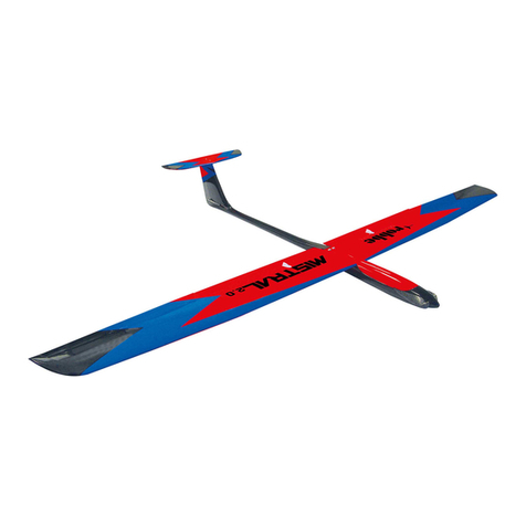
ROBBE ZLIN 50LX RED BULL 1600MM ARF Operating instructions

ROBBE

ROBBE ZLIN 50LX RED BULL 1600MM ARF Operating instructions

ROBBE Arcus Sport User manual

ROBBE

ROBBE Arcus Sport User manual

ROBBE AIRBULL 3129 User manual

ROBBE

ROBBE AIRBULL 3129 User manual

ROBBE Mistral 2.0 Instruction Manual

ROBBE

ROBBE Mistral 2.0 Instruction Manual

ROBBE Wingo 2 Instruction Manual

ROBBE

ROBBE Wingo 2 Instruction Manual

ROBBE MONSUN V2 2663 Instruction Manual

ROBBE

ROBBE MONSUN V2 2663 Instruction Manual

ROBBE WINDSTAR 1087 User manual

ROBBE

ROBBE WINDSTAR 1087 User manual

ROBBE Valdivia User manual

ROBBE

ROBBE Valdivia User manual

ROBBE ARCUS E-RISE 500 RTF User manual

ROBBE

ROBBE ARCUS E-RISE 500 RTF User manual

Popular Toy manuals by other brands

Lionel U.S. ARMY SWITCHER 41 owner's manual

Lionel

Lionel U.S. ARMY SWITCHER 41 owner's manual

LEGO Explosion Studio 1352 manual

LEGO

LEGO Explosion Studio 1352 manual

Vintage Model Co Balsa Basics Spitfire Building instructions

Vintage Model Co

Vintage Model Co Balsa Basics Spitfire Building instructions

Faller 564 manual

Faller

Faller 564 manual

HOMCOM 370-299V00 Assembly instruction

HOMCOM

HOMCOM 370-299V00 Assembly instruction

LEGO 60081 manual

LEGO

LEGO 60081 manual

Bontempi 13 3225 owner's manual

Bontempi

Bontempi 13 3225 owner's manual

Brubaker Models WildKard Assembly and operation instructions

Brubaker Models

Brubaker Models WildKard Assembly and operation instructions

Build Your Own MINI-BUILDS ANKYLOSAURUS instructions

Build Your Own

Build Your Own MINI-BUILDS ANKYLOSAURUS instructions

Alien Aircraft Corp K-308 Assembly instructions

Alien Aircraft Corp

Alien Aircraft Corp K-308 Assembly instructions

Horizon Hobby Sparc! AEROLITE 9437 owner's manual

Horizon Hobby

Horizon Hobby Sparc! AEROLITE 9437 owner's manual

REVELL MiL Mi-26 Halo Assembly manual

REVELL

REVELL MiL Mi-26 Halo Assembly manual

POLA 331727 quick start guide

POLA

POLA 331727 quick start guide

Radiosistemi rr8 instruction manual

Radiosistemi

Radiosistemi rr8 instruction manual

THUNDER TIGER raptor e700 instruction manual

THUNDER TIGER

THUNDER TIGER raptor e700 instruction manual

Align Trex 700 Electric conversion instruction manual

Align

Align Trex 700 Electric conversion instruction manual

Braemere Models Littleborough Lancs Houghton Parkhouse Platinum Four Deck Livestock... instruction manual

Braemere Models

Braemere Models Littleborough Lancs Houghton Parkhouse Platinum Four Deck Livestock... instruction manual

The Learning Journey Techno Gears Marble Mania SIDEWINDER 3.0 instruction manual

The Learning Journey

The Learning Journey Techno Gears Marble Mania SIDEWINDER 3.0 instruction manual

manuals.online logo
manuals.online logoBrands
  • About & Mission
  • Contact us
  • Privacy Policy
  • Terms and Conditions

Copyright 2025 Manuals.Online. All Rights Reserved.