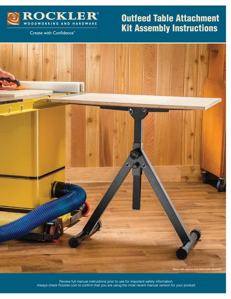
Rockler Bench Dog Tools ProMAX User manual

Review full instructions prior to use for important safety information.
Always check Rockler.com to conrm that you are using the most
recent version for your product.
PROMAX
CAST IRON ROUTER
TABLE EXTENSION
INSTRUCTIONS
Effective August 2020


1
Index
General Safety Warnings . . . . . . . . . . . . . . . . . . . . . . . . . . . . . . . . . . . . . . . . . .2
Product Specific Warnings . . . . . . . . . . . . . . . . . . . . . . . . . . . . . . . . . . . . . . . . .4
Parts List . . . . . . . . . . . . . . . . . . . . . . . . . . . . . . . . . . . . . . . . . . . . . . . . . . . . . . .5
Attaching the Table . . . . . . . . . . . . . . . . . . . . . . . . . . . . . . . . . . . . . . . . . . . . . . .6
Leveling the Router Plate . . . . . . . . . . . . . . . . . . . . . . . . . . . . . . . . . . . . . . . . . .8

2BP0918
This product is designed only for specific applications as defined in the instructions and
should not be modified or used for any manner not described in these instructions. Use
only recommended accessories. Before using the ProMax Cast Iron Router Table Extension:
READ, UNDERSTAND and FOLLOW ALL INSTRUCTIONS AND SAFETY WARNINGS.
KEEP THESE INSTRUCTIONS READILY AVAILABLE FOR FUTURE REFERENCE.
>Always confirm that you are using the most
recent version of the Instructions and safety
warnings for your product (see the
Instructions link on the product
page at Rockler.com).
>Before using another tool with this product,
always read, understand and follow the
instructions and safety warnings in the
owner’s manual for that tool. If you do not
have the owner’s manual, obtain one from
the tool’s manufacturer before using it with
this product.
>Before using any chemical with this
product, always read, understand and
follow all safety warnings and guidelines
in the manufacturer’s Safety Data
Sheet (SDS; formerly called “MSDS”),
especially regarding:
• How to safely use the chemical,
including potential hazards and
recommended first aid measures;
• Personal safety equipment required
to safely use the chemical (e.g. gloves,
eye protection, mask/respirator, etc.);
• Proper and safe handling, storage
and disposal of the chemical.
>Before using this product, review and verify
that all tools to be used with it have safety
equipment installed and are in proper
working order as defined by the tool’s
owner’s manual.
>Do not use this product until you have read
and are confident you understand:
• Product Specific Warnings (p. 4);
• Parts List (p. 5);
• Attaching the Table (pp. 6 - 8);
• Leveling the Router Plate (pp. 8 - 9).
>The user assumes all risk and responsibility
for the proper and safe use of this product
and for ensuring product suitability for the
intended application.
>It is the sole responsibility of the purchaser
of this product to ensure that any anyone
you allow to use this product reads and
complies with all instructions and safety
precautions outlined in this manual
prior to use.
>Follow all standard shop safety
practices, including:
• Keep children and bystanders away
from the tool operating area;
• Do NOT use power tools in explosive
environments, or in the presence of
flammable liquids, fumes or dust;
• TURN OFF AND UNPLUG all power
tools BEFORE making any adjustments
or changing accessories;
• Remain alert and use good judgment.
Do not use this product if you are in any
way impaired by medications, alcohol,
drugs or fatigue;
• Keep your work area well lit and clean;
• Dress appropriately. Secure loose
clothing, remove all jewelry and tie
up long hair before using this product;
• ALWAYS wear safety glasses, hearing
protection and respiratory protection that
complies with ANSI safety standards;
• Use dust collection tools and dust face
masks to reduce exposure to dust;
• Use safety equipment such as
featherboards, push sticks and push
blocks, etc., when appropriate;
• Maintain proper footing at all times
and do not overreach;
• Do NOT force woodworking tools.
>These warnings and instructions Do
NOT represent the total of all information
available regarding tool safety, use and
technique. Always seek out opportunities
to learn more and improve your skills
and knowledge.
Drilling, sawing, sanding
or machining wood products can expose
you to wood dust, a substance known to
the State of California to cause cancer.
Avoid inhaling wood dust or use a dust
mask or other safeguards for personal
protection. For more information go to
www.P65Warnings.ca.gov/wood.
GENERAL SAFETY WARNINGS
2BP1219
3
Danger indicates a hazardous situation that, if not avoided, will result
in death or serious injury.
Warning indicates a hazardous situation that, if not avoided, could
result in death or serious injury.
Caution indicates a hazardous situation that, if not avoided, may result
in minor or moderate injury or property damage.
Notice indicates important or helpful information and/or user tips.
SAFETY WARNING KEY

24
>When using this product with a table
saw, in addition to the warnings
provided herein, the user must
comply with all warnings, instructions
and safety guidelines provided by the
manufacturer of the table saw and by
the manufacturer(s) of any accessories
used with the table saw. Failure to do
so may result in tipping of the table
saw and serious personal injury.
>Before attempting to install the ProMax
table on your table saw, refer to the
saw’s instruction manual to make sure
the manufacturer allows installation of
accessories such as the ProMax. If such
accessories are not allowed, Do NOT
install the ProMax.
>Install the ProMax table ONLY on
contractor-style or cabinet table saws
with cast iron tables at least 27" deep.
Tables deeper than 27" will require the
use of shims to fill the space between
the fence rails and the ProMax.
>Do NOT install on portable or jobsite
table saws.
>Do NOT install the ProMax table in
place of the left extension wing on
left-tilt cabinet saws or in place of the
right extension wing on right-tilt cabinet
saws. The location of the saw’s motor
does not provide sufficient clearance
for the router.
>If installing on a right-tilt cabinet saw with
an extension and longer fence rails, the
ProMax table may be mounted to the
far right to avoid the protruding motor.
However, the ProMax MUST be mounted
to and supported by the two steel rails
and the legs that also support
the extension.
>If your table saw has casters or a mobile
base, do NOT attempt to operate the table
saw or the router mounted in the ProMax
if the casters or wheels are in the rolling
position. ALWAYS position the saw on a
firm, level surface. ALWAYS check to
make sure the saw base will not move
or shift during use. Failure to do so may
result in tipping of the table saw and
serious personal injury.
>Use the appropriate bolts and hardware
included with your ProMax to install it on
your saw. Do NOT use the bolts that held
the extension wing to your table saw, as
they may not be sufficiently strong (Grade
5) or the proper length. If the necessary
bolt size is not supplied with the ProMax,
you must purchase your own
Grade 5 bolts.
>The ProMax Router Tabletop is heavy.
To mount it to your table saw, you will
need the help of another adult to hold it
in place. Use proper lifting techniques.
>Before using a router in the ProMax
table, be sure to read, understand
and follow all the instructions and
safety recommendations in the
router’s operator’s manual.
PRODUCT SPECIFIC SAFETY WARNINGS
> A router plate must be purchased separately. The ProMAX
accommodates all Rockler router plates.

5
Quantity
1 Cast Iron Router Tabletop 1
2 Heavy Rectangular Washer 3
3 M10-1.5 x 40mm Hex Bolt 3
4 7/16"-20 x 11⁄2" Hex Bolt 3
5 5/16"-18 x 11⁄2" Hex Bolt 4
6 5/16" Flat Washer 8
7 5/16" Lock Washer 4
8 5/16" Hex Nut 4
9 1/4"-20 Plate Leveling Set Screw 10
10 1/4"-20 Hex Nut 12
11 J-Hook 2
PARTS LIST
1
43
5
9
11
26
8
7
10

26
Attaching the Table
These instructions
describe mounting the ProMax in
place of the left extension wing on a
contractor-type table saw. The basic
procedure described here can be used
to mount the ProMax to a cabinet saw or
to the other side of the table saw, with
the exception of to the far right of cabinet
saws with long right extensions. As
noted in the Product Specific Warnings,
in these cases the ProMax MUST be
mounted to and supported by the two
steel rails and the legs that also support
the extension.
1. Using the manual that came with your table saw
as a reference, carefully remove the saw’s left
extension wing. Fig. 1.
2. Note the hole pattern on the edge of your table
saw’s cast iron top, where you removed the
extension wing. Some saws have a four-hole
pattern. Many have a three-hole pattern. Fig. 2.
In most cases, the
extension wings that come with your
table saw are supported by the fence
rails. When bolted directly to your table
saw, the ProMax requires no support
from the fence rails, and the fence
rails do not need to be fastened to
the ProMax.
>Use the appropriate bolts and
hardware included with your
ProMax to install it on your saw.
Do NOT use the bolts that held the
extension wing to your table saw,
as they may not be sufficiently
strong (Grade 5) or the proper
length. If the necessary bolt size
is not supplied with the ProMax,
you must purchase your own
Grade 5 bolts.
THESE WARNINGS PERTAIN TO
ALL REMAINING STEPS:
Fig. 2
Fig. 1
4
3
4
3
4
3
4

7
3. Gather the hardware required for installation
on your particular saw.
Four-hole applications:
• Most saws with four-hole patterns use
5/16"-18 bolts. If the bolt size is not
5/16"-18, you must supply your own
Grade 5 bolts.
• The Heavy Rectangle Washers (2) MUST be
used for the middle two holes, as shown in
Fig. 3.
• Each 5/16"-18 Hex Bolt receives two 5/16" flat
washers, one lock washer and one nut. The bolts
going in the middle two holes also must each get
a Heavy Rectangular Washer (2), as mentioned
above; the Heavy Rectangular Washers must be
on the inside face of the ProMax table.
• Some saws have tapped holes in their cast-iron
tops, rather than through holes, and the bolts
secure into these holes.
Three-hole applications:
• Check to see whether the included M10-1.5 x
40mm Hex Bolts (3) or 7/16"-20 x 11⁄2" Hex
Bolts (4) fit your saw. If neither fits, you must
supply your own Grade 5 bolts.
• The Heavy Rectangle Washers (2) MUST be
used for all three holes in three-hole
applications, as shown in Fig. 4.
• Some saws have tapped holes in their cast-iron
tops, rather than through holes, and the bolts
secure into these holes.
Fig. 4
Fig. 3
Heavy Rectangle Washers (2)
MUST be used here
Heavy Rectangle Washers (2)
MUST be used here

28
If installing the Pro
Lift router lift (52429, sold separately) in
your ProMax tabletop, you will need to
remove the tabs extending from the left
and right edges of the tabletop’s center
opening. For instructions on how to do
this, go to Rockler.com
In the corners of the
center opening that have three holes,
install Plate Leveling Set Screws (9) only
in the two outer holes. The center hole is
for securing the router plate.
5. With the help of another adult, lift the ProMax
table into position, aligning its mounting holes
with the mounting holes in your saw’s cast-iron
table. While your helper holds the table in position,
use the hardware specified in Step 3 for your
application to attach the ProMax table to your
saw. Just snug the bolts for now. Fig. 5.
6. Make sure the edges of the ProMax table and the
saw table are flush, and then tighten the bolts
gradually and evenly. Fig. 6. If necessary, use a
soft-tipped mallet to lightly tap the table surfaces.
If the ProMax table is not flat with your table saw’s
table, you may need to shim it with paper or brass
shims between the tables. Slight inaccuracies in
alignment rarely pose a significant problem.
7. The J-Hooks (11) are included to provide a place
for storing a fence when the router table is not in
use. Thread a 1/4"-20 Hex Nut (10) onto each of
the two J-Hooks and then thread the hooks about
3/8" into the tapped holes in the table. Tighten the
1/4"-20 Hex Nut with a 7/16" wrench. Fig. 7.
Leveling the Router Plate
1. Fit the router plate (sold separately) in the center
opening of the ProMax tabletop (1).
4. Check the surfaces of the ProMax extension and
the cast-iron table of your table saw. Make sure
both surfaces are smooth, flat and free of burrs.
If necessary, file edges to remove burrs.
The ProMax Router
Tabletop is heavy. To mount it to your
table saw, you will need the help of
another adult to hold it in place. Use
proper lifting techniques.
Fig. 5

9
Check Rockler.com for updates. If you have further
questions, please contact our Technical Support
Department at 1-800-260-9663 or
support@rockler.com
2. Working from the underside of the table, thread
ten 1/4"-20 x 1" Plate Leveling Set Screws (9) in
the adjustment holes. Then install a 1/4"-20 Hex
Nut (10) on the bottom of each Plate Leveling
Set Screw. Fig. 8.
3. Use a hex wrench to adjust the 1/4"-20 x 1" Plate
Leveling Set Screws (9) until the router plate is
flush with the ProMax tabletop (1).
4. Hold each 1/4"-20 x 1" Plate Leveling Set Screw (9)
with the hex wrench and use a 7/16" wrench to
tighten the 1/4"-20 Hex Nut (10). This will prevent
the Leveling Set Screws from moving. You might
need to fine tune the settings after installing
your router.
5. Once the router plate is level with the table all
the way around, use the plate locking bolts that
came with the router plate to secure it in place.
Fig. 6
Fig. 8
Fig. 7

Distributed by Rockler Companies, Inc.
4365 Willow Dr. Medina, MN 55340
23600
Rev 08/20
1-800-279-4441
www.rockler.com
This manual suits for next models
1
Table of contents
Other Rockler Tools Storage manuals
Popular Tools Storage manuals by other brands

RAIMONDI
RAIMONDI BM180 Use and maintenance manual

Sealey
Sealey API1500 quick start guide

Seaside Casual
Seaside Casual Sonoma 36 Assembly instructions

IAC INDUSTRIES
IAC INDUSTRIES Quick Ship WORKMASTER Assembly instructions

Seville Classics
Seville Classics HOME UltraGuard Workcenter Island UHD20109 Assembly instructions

Tennsco
Tennsco INDUSTRIAL WORKBENCH With Steel Top Assembly Instructions/Parts Manual