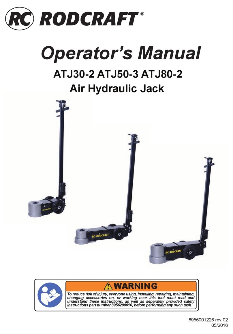
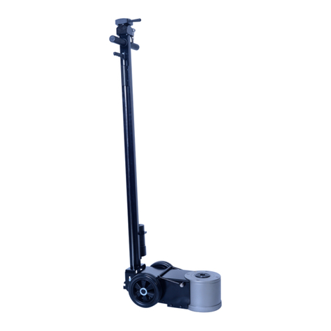
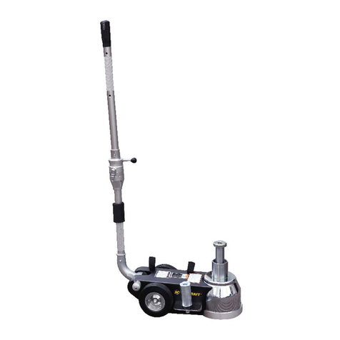
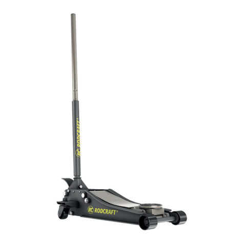
RODCRAFT ATJ30-1H User manual

Operator’s Manual
ATJ30-1H
Air Hydraulic Jack
8956001674 rev 01
13/11/2017
WARNING
To reduce risk of injury, everyone using, installing, repairing, maintaining,
changing accessories on, or working near this tool must read and
understand these instructions, as well as separately provided safety
instructions part number 8956200010, before performing any such task.

Fig. 01
Fig. 02

Fig. 03
Fig. 04

Fig. 05 & 06
OIL TYPE : ISO VG#15

1 2 3 4 5 6 7 8 9 10
EN Piston One-way walve air route oil route Air Inlet Valve Air Cylinder Check Vlave Oil tank Working Theory
(lifting up)
Working Theory (lifting
down)
DE Kolben Einweg-Ventil Luftuss Öluss Lufteinlass Druckluftzylinder Rückschlagventil Öltank Arbeitsuss
(Hubvorgang)
Arbeitsuss (Senk-
vorgang)
FR Piston Clapet unidirec-
tionnel Circuit d'air Circuit d'huile Clapet d'entrée d'air Vérin pneumatique Clapet antiretour Réservoir d'huile
Fonctionnement
théorique
(levage)
Fonctionnement théo-
rique (descente)
ES Pistón Válvula unidi-
reccional ruta de aire ruta de aceite Válvula de entrada
de aire Cilindro de aire Válvula de retención Depósito de
aceite
Teoría de trabajo
(elevación)
Teoría de trabajo
(descenso)
IT Pistone Valvola unidire-
zionale Percorso dell'aria Percorso dell'olio Valvola di aspirazione
dell'aria Cilindro pneumatico Valvola di ritegno Serbatoio
dell'olio
Teoria (solleva-
mento) Teoria (abbassamento)
NL Zuiger Eenwegs golf luchtlijn olielijn Luchtinlaatklep Luchtcilinder Terugslagklep Olietank Werktheorie
(tillen)
Werktheorie
(neerlaten)
RU Поршень Одноходовый
клапан воздуховод маслопровод Впускной воздушный
клапан Воздушный цилиндр Обратный клапан Масляный бак Принцип работы
(поднимание)
Принцип работы
(опускание)
SV Kolv Envägsventil luftväg oljeväg Luftinloppsventil Luftcylinder Kontrollventil Oljetank Arbetsteori (lyfta
upp) Arbetsteori (lyfta ned)
DA Stempel En-vejs-ventil luftrute olierute Luftindgangsventil Luftcylinder Kontraventil Olietank Arbejdsteori
(løftning op)
Arbejdsteori (løftning
ned)
NO stempel énveis ventil luftkurs oljekurs luftinntaksventil luftsylinder kontrollventil oljetank Arbeidsteori
(oppløfting)
Arbeidsteori (ned-
senking)
FI Mäntä Suuntaventtiili ilman kulku öljyn kulku Ilman imuventtiili Ilmasylinteri Suuntaventtiili Öljysäiliö Nostoteoria
(nostaa ylös)
Nostoteoria (laskee
alas)
PT Pistão Válvula de
uma via percurso do ar percurso do óleo Válvula de entrada
de ar Cilindro de ar Vericar válvula Depósito de óleo Teoria do trabalho
(elevação)
Teoria do trabalho
(descida)
EL Έμβολο Μονόοδη
βαλβίδα διαδρομή αέρα διαδρομή λαδιού Βαλβίδα εισόδου
αέρα Κύλινδρος αέρα Βαλβίδα ελέγχου Δεξαμενή λαδιού
Θεωρία
λειτουργίας
(ανύψωση)
Θεωρία λειτουργίας
(κατέβασμα)
PL Tłok Zawór jedno-
drogowy droga powietrza droga oleju Zawór wlotowy
powietrza
Siłownik pneuma-
tyczny Zawór zwrotny Zbiornik oleju Zasada działania
(podnoszenie)
Zasada działania
(opuszczanie)
CS Píst Jednocestný
ventil vzdušná cesta olejová cesta Přívodní ventil
vzduchu Vzduchový válec Zpětný ventil Olejová nádrž Teorie fungování
(zvedání)
Teorie fungování
(spouštění)
SK Piest Jednosmerný
ventil vzduchová trasa olejová trasa Ventil vstupu vzduchu Vzduchový valec Kontrolný ventil Olejová nádrž Pracovná teória
(zdvih)
Pracovná teória
(spustenie nadol)
HU Dugattyú Egyirányú
szelep levegő útvonala olaj útvonala Légbeszívó szelep Pneumatikus henger Visszacsapó szelep Olajtartály Működési elv
(emelés)
Működési elv
(leeresztés)
SL Bat Enopotni ventil zračna pot oljna po Vhodni zračni ventil Zračni valj Krmilni ventil Rezervoar
za olje
Delovna teorija
(dviganje)
Delovna teorija
(spuščanje)
LT Stūmoklis Vienakryptis
vožtuvas oro kelias alyvos kelias Oro įleidimo vožtuvas Pneumatinis cilindras Patikros vožtuvas Alyvos bakas Darbinė teorija
(kėlimas)
Darbinė teorija
(nuleidimas)
LV Virzulis Vienvirziena
vārsts gaisa ceļš eļļas ceļš Gaisa ievades vārsts Gaisa cilindrs Pārbaudiet vārstu Eļļas tvertne Darba toerija
(pacelšana)
Darba teorija
(nolaišana)
HR Stap Jednosmjerni
ventil Zračni vod Uljni vod Ventil za ulaz zraka Zračni cilindar Regulacijski ventil Uljni spremnik Načelo rada
(podizanje)
Načelo rada
(spuštanje)
RO Piston Supapă de
reținere circuitul aerului circuitul uleiului Supapă de admisie
aer Cilindru pneumatic Supapă de închidere Rezervor de ulei
Schema de
funcționare (la
ridicare)
Schema de funcționare
(la coborâre)
BG Бутало Еднопосочен
клапан въздухопровод маслопровод Входящ въздушен
клапан Въздушен цилиндър Възвратен клапан Резервоар за
масло
Принцип
на работа
(повдигане)
Принцип на работа
(сваляне)
ET Kolb Ühesuunaline
klapp õhutrass õlitrass Õhu sisselaskeklapp Õhusilinder Tagasilöögiklapp Õlimahuti Tööpõhimõte
(tõstmine)
Tööpõhimõte (lange-
tamine)
TR Piston Tek yönlü valf hava güzergahı yağ güzergahı Hava Giriş Val Hava Silindiri Çek Val Yağ deposu Çalışma Teorisi
(yukarı kaldırma)
Çalışma Teorisi (aşağı
indirme)
ZH 活塞 单向阀 气路 油路 进气阀 气缸 止回阀 油罐 工作原理(提升
向上) 工作原理(提升向下)
JA ピストン 一方向弁 エアルート オイルルート チェックバルブ オイルタンク 作業理論(持ち
上げ)
作業理論(引き下
ろし)
KO 피스톤 한방향 밸브 공기 경로 오일 경로 공기 흡입 밸브 공기 실린더 밸브 점검 오일 탱크 작업 이론(올리기) 작업 이론(내리기)
Translation for Fig.05 & 06

Fig. 07
Fig. 08

EN English ATJ30-1H
Air Hydraulic jack
2. Machine type(s)
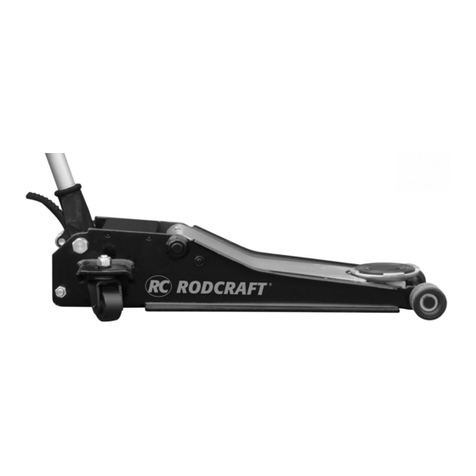
• An Air-Hydraulic jack is a device to lift a vehicle up to for accessibility during repair and maintenance.No other use permitted. For professional use only.
• A Jack is only a lifting device and should never be used for transporting and/or loading a vehicle. Lifting a vehicle with person inside is prohibited.
Moving the jack with load is prohibited.
• Please read the instructions carefully before starting the machine.
3. Mounting instruction
WARNING
Make sure every parts are fixed and tightened.
• First loosen the screw attached to the handle. (see fig. 01)
• Connect the hose and the spring to the lifting device. The white hose is connected to the left inlet, the Black hose is connected to the right inlet.
• To assemble the handle, see figure 03.
• To install the control lever, loosen the screw and rotate the control lever into the hole. (see fig.04)
• Do a complete cycle of lifting and lowering with no load, to purge air from the hydraulic system.
Document Ref: 8940169914_REV:01 _ 05-2012
Scale: 1:1
Caution
Working area of 1 m must be kept free both in front of and behind the machine while it is in operation so that it is always
easily accessible.
4. Operation
• Verify the control lever is in the neutral position.
• Connect the shop air supply to the jack. Minimum air pressure is 9 bar. Install an air filter/lubricator in the shop air line, because water in the air line will
damage the jack.
• Move the control lever clockwise to raise the saddle to the contact point. Move the control lever to neutral position.
• Check the placement of the jack. The load must be centered on the jack saddle. Avoid jack wheel obstructions such as gravel, tools, or uneven
expansion joints.
• Move the control lever clockwise to finish lifting the vehicle.
• Immediately place approved support stands under the vehicle’s lifting points (recommended by the vehicle manufacturer).
• To lower the load, move the control lever counter clockwise.
WARNING
• Brake vehicle. Chock vehicle tires that are still in contact with the ground.
• SLOWLY and CAREFULLY lower the vehicle onto the support stands by pushing the control lever counter
clockwise.
• It is not allowed to work under the raised load until it is secured by suitable means.
• The operator shall be provided with all necessary information about training and about pumping and translating
forces.
1. Technical Data (See gures 08)
Max. Lifting capacity Pressure Air Consumption Hydraulic oil Quantity
ISO VG#15 Sound pressure Weight
Unit [kg] [bar] [l/min] [l] dB [kg]
ATJ30-1H 30000 9-12 11,5 3,4 76,4 87
Static coefficient test: 1.5 / Dynamic Coefficient test: 1.2
All values are current as of the date of this publication. For the latest information please visit www.rodcraft.com.
Declaration of noise and vibration statement
These declared values were obtained by laboratory type testing in accordance with the stated standards and are suitable for comparison with the
declared values of other tools tested in accordance with the same standards. These declared values are not adequate for use in risk assessments and
values measured in individual work places may be higher. The actual exposure values and risk of harm experienced by an individual user are unique and
depend upon the way the user works, the workpiece and the workstation design, as well upon the exposure time and the physical condition of the user.
exposure, in an individual risk assessment in a work place situation over which we have no control. This tool may cause hand-arm vibration syndrome
if its use is not adequately managed. An EU guide to managing hand-arm vibration can be found at www. pneurop.eu/uploads/documents/pdf/PN3-02-
NV_Declaration_info_sheet_0111.pdf We recommend a programme of health surveillance to detect early symptoms which may relate to noise or vibration

EN English ATJ30-1H
Air Hydraulic jack
6. Trouble Shooting
Fault Cause Remedy
AThe hydraulic piston is not rising
up with or without load
1. Not enough air pressure supply to
the jack
2. hydraulic piston is missing oil
3. Failure of the pneumatic pump
1.a Supply air pressure within the tolerances specify into the
manual and on the product nameplate
tie-ins (Fig.02)
2.b failure of the hydraulic system, product to be repair by
authorized repair center
3. Product to be repaired by authorized repair facility
BThe hydraulic piston is not
reaching the maximum position hydraulic piston is missing oil
CThe hydraulic piston cannot stand
in upper position
1. hydraulic piston is leaking oil.
2. Failure of the pneumatic pump
1. Check the product to detect potential oil leakage from
the piston. Send the product to authorized repair facility for
reparation
2. Product to be repaired by authorized repair facility
DThe hydraulic piston is not going
down
1. Not enough air pressure supply to
the jack
2. Failure of the pneumatic pump
3. Air leakage from the dustproof gasket
1.a Supply air pressure within the tolerances specify into the
manual and on the product nameplate
tie-ins (Fig.02)
2.&3. Product to be repaired by authorized repair facility
5. Maintenance instruction
Document Ref: 8940169914_REV:01 _ 05-2012
Scale: 1:1
Caution
• Do not use damaged/deformed product. If abnormal noise or vibration occurs, stop use immediately, then inspect
and ask manufacturer for help.It is recommended that this inspection be made by a manufacturer’s or supplier’s
authorized repair facility.
• The greatest single cause of failure in hydraulic units is dirt. Keep the service jack clean and
well lubricated to prevent foreign matter from entering the system. If the jack has been exposed to rain, snow, sand,
or grit, it must be cleaned before it is used.
• Store the jack, with pistons completely retracted, in a well-protected area where it will not be exposed to corrosive vapors, abrasive dust, or any other
harmful elements.
• Periodically check the condition of the product.
• Store the product in dry and non-corrosion environment.
• Owners and/or operators should be aware that repair of this equipment may require specialized knowledge and facilities. It is recommended that an
annual inspection of the product be made by a manufacturer’s or supplier’s authorized repair facility and that any defective parts, decals, or safety labels
or signs be replaced with manufacturer’s or supplier’s specified parts. A list of authorized repair facilities is available from the manufacturer or supplier,
please call them for help.
• Any product that appears to be damaged in any way, is found to be worn, or operates abnormally SHALL BE REMOVED FROM SERVICE UNTIL
REPAIRED. It is recommended that necessary repairs be made by a manufacturer’s or supplier’s authorized repair facility if repairs are permitted by the
manufacturer or supplier.
• Only attachments and/or adapters supplied by the manufacturer shall be used.
7. EU Declaration of conformity
We : Rodcraft Customer Center Langemarckstr.35 bis 45141 Essen- Germany
Declare that the product(s): ATJ30-1H Serial Number: 001 - 999
Machine type(s): Air Hydraulic jack Origin of the product: China
is in conformity with the requirements of the council Directives on the approximation of the laws of the Member States relating : to “Machinery“
2006/42/EC (17/05/2006)
applicable harmonised standard(s) : EN 1494:2000 + A1:2008
Name and position of issuer: Pascal Roussy ( R&D Manager)
Place & Date: Saint-Herblain, 13/11/2017
Technical file available from EU headquarter. Pascal Roussy, R&D manager CP Technocenter 38, rue Bobby Sands - BP10273 44800 Saint Herblain -
France
Copyright 2017, Rodcraft
All rights reserved. Any unauthorized use or copying of the contents or part thereof is prohibited. This applies in particular to trademarks, model
denominations, part numbers and drawings. Use only authorized parts. Any damage or malfunction caused by the use of unauthorized parts is not
covered by Warranty or Product Liability.
Original Instructions

DE Deutsch ATJ30-1H
Luft-Hydraulik-Hubwagen
2. Typ(en)
•
• Ein Heber ist nur eine Hebevorrichtung und darf nie zum Transportieren bzw. Beladen eines Fahrzeuges verwendet werden. Anheben eines Fahrzeugs
mit Personen darin ist verboten. Der Wagenheber darf nicht mit Last bewegt werden.
•
3. Montageanleitung
WARNING
Stellen Sie sicher, dass alle Teile befestigt und festgezogen sind.
•
• Schlauch und Feder an der Hubeinheit anschließen. Heber wird der weiße Schlauch links angeschlossen, der andere Schlauch rechts.
•
• Schraube im Schalter lösen und den Hebel zur Schraubenöffnung drehen. (Fig.04)
•
entfernt.
Document Ref: 8940169914_REV:01 _ 05-2012
Scale: 1:1
Caution
4. Bedienung
• Schraube im Schalter lösen und den Hebel zur Schraubenöffnung drehen.
• Der Hebel muss sich nun in Neutral Stellung befinden.
• -
•
•
• Hebel im UZS drehen um den Hebevorgang zu stoppen.
•
• Zum Senken der Last den Hebel gg. den UZS drehen
WARNING
• Bremsen Sie das Fahrzeug. Verkeilen Sie Fahrzeugreifen, die immer noch Kontakt mit dem Boden haben.
• Das Fahrzeug LANGSAM und VORSICHTIG auf de Stützen ablassen, indem der Hebel gg. den UZS gedreht wird.
• Die Arbeit unter der angehobenen Last darf erst begonnen werden, nachdem geeignete Sicherheitsvorkehrungen
getroffen wurden.
• Dem Bediener mssen alle notwendigen Einweisungsinformationen hinsichtlich der Pumpen- und Umrechnungsfak-
toren fr die Leistungseinheiten zur Verfgung stehen.
1. Technische Daten (Siehe Abbildungen 08)
Max. Tragkraft Druck Luftverbrauch Hydraulikölmenge
ISO VG#15 Schalldruck Gewicht
Unit [kg] [bar] [l/min] [l] dB [kg]
ATJ30-1H 30000 9-12 11,5 3,4 76,4 87
Geräuschemissions- und Vibrationsemissionserklärung
angegebenen Werten anderer Werkzeuge geeignet, die entsprechend derselben Normen getestet wurden. Diese angegebenen Werte sind nicht
Aufbau des Arbeitsplatzes, der Expositionszeit und dem physischen Zustand des Nutzers ab. Wir, RODCRAFT PNEUMATIC TOOLS, können nicht

DE Deutsch ATJ30-1H
Luft-Hydraulik-Hubwagen
6. Fehlersuche
Fehler Ursache Behebung
A
oder ohne Last nicht heraus.
2. Ölmangel im Hydraulikkolben
3. Störung der Pneumatikpumpe
1.a Die Druckluftversorgung muss den Angaben in
der Anleitung und dem Typenschild auf dem Produkt
entsprechen.
2.b Störung im Hydrauliksystem, Produkt muss von einem
3. Produkt muss von einer autorisierten Werkstatt
repariert werden
BDer Hydraulikkolben erreicht
nicht die maximale Position. Ölmangel im Hydraulikkolben
CDer Hydraulikkolben verbleibt
nicht in der oberen Stellung.
1. Ölleck am Hydraulikkolben
2. Störung der Pneumatikpumpe
autorisierte Werkstatt zur Reparatur schicken
2. Produkt muss von einer autorisierten Werkstatt
repariert werden
D
2. Störung der Pneumatikpumpe
3. Druckluftverlust an der Staubdichtung
1.a SDie Druckluftversorgung muss den Angaben in
der Anleitung und dem Typenschild auf dem Produkt
entsprechen.
2.&3. Produkt muss von einer autorisierten Werkstatt
repariert werden
5. Wartungsanweisungen
Document Ref: 8940169914_REV:01 _ 05-2012
Scale: 1:1
Caution
• Verwenden Sie keine beschädigten/deformierten Produkte. Falls ungewöhnliche Geräusche oder Vibrationen
auftreten, beenden Sie sofort die Nutzung. Führen Sie dann eine Überprüfung durch und bitten Sie den Hersteller
um Hilfe.Es wird empfohlen, dass diese Überprüfung durch eine vom Hersteller oder Lieferanten autorisierte
Reparaturwerkstatt erfolgt.
• Die häufigste einzelne Ursache für Ausfälle in Hydraulikaggregaten ist Schmutz. Halten
Sie den Hubwagen sauber und gut geschmiert, damit keine Fremdkörper in das System eindringen können. Wenn
der Hubwagen Regen, Schnee, Sand oder Splitt ausgesetzt war, muss er vor der nächsten Verwendung gereinigt
werden.
•
•
• Lagern Sie das Produkt an einem trockenen und nicht korrosiven Umgebung.
•
an.
•
VERWENDET WERDEN, BIS ES REPARIERT IST. Es wird empfohlen, dass die notwendigen Reparaturen durch eine vom Hersteller oder Lieferanten
autorisierte Reparaturwerkstatt erfolgt, falls Reparaturen vom Hersteller oder Lieferanten erlaubt werden.
•
7. EG-KONFORMITÄTSERKLÄRUNG
Wir: Rodcraft Customer Center Langemarckstr.35 bis 45141 Essen- Germany
Erklären hiermit, dass das (die) Produkt(e): ATJ30-1H Serial Number: 001 - 999
Typ(en): Luft-Hydraulik-Hubwagen Produktherkunft: China
den Anforderungen der EG-Richtlinie zur Angleichung der Rechtsvorschriften der Mitgliedsstaaten entspricht: für “Maschinen” 2006/42/EC
(17/05/2006)
Geltende harmonisierte Norme(n): EN 1494:2000 + A1:2008
Name und Position des Ausstellers: Pascal Roussy ( R&D Manager)
Ort und Datum: Saint-Herblain, 13/11/2017
Technische Datei bei EU-Hauptbüro erhältlich. Pascal Roussy, R&D manager CP Technocenter 38, rue Bobby Sands - BP10273 44800 Saint Herblain -
France
Copyright 2017, Rodcraft
Produkthaftung nicht abgedeckt.
FR Français ATJ30-1H
Cric aérohydraulique
2. Type(s) de machine
• Un cric aérohydraulique est un équipement servant à lever un véhicule pour permettre un accès facile pendant les réparations ou l'entretien.Aucune
autre utilisation n'est autorisée. Réservé à un usage professionnel.
• Un cric est uniquement un appareil de levage et ne doit jamais être utilisé pour transporter et/ou charger un véhicule. Il est interdit de lever un véhicule
dans lequel se trouve une personne. Il est interdit de déplacer le cric lorsqu‘il est chargé.
• Veuillez lire attentivement les instructions avant de démarrer la machine.
3. Instructions de montage
WARNING
Vérifier que toutes les pièces sont fixées et bien serrées.
• Commencer par desserrer les vis de la poignée. (Voir fig. 01).
• Raccorder le flexible et le ressort au dispositif de levage. Le flexible blanc est raccordé à l'entrée gauche, l'autre flexible est raccordé à l'entrée droite.
• Pour le montage de la poignée, voir la figure 03.
• Pour assemble le levier de commande, desserrer la vis et visser le levier, comme indiqué sur la figure 04.
• Effectuer un cycle complet de levage et de descente à vide, afin de purger l‘air du circuit hydraulique.
Document Ref: 8940169914_REV:01 _ 05-2012
Scale: 1:1
Caution
Une zone de travail d‘1 m doit rester libre, à la fois à l‘avant et à l‘arrière de la machine lorsqu‘elle est en fonctionnement,
4. Utilisation
• Vérifier que le levier de commande est en position neutre.
• Raccorder l‘alimentation en air de l‘atelier au cric. La pression d‘air minimale est de 9 bars. Installer un filtre à air/lubrificateur sur le circuit d‘air de
l‘atelier, sans quoi l‘eau présente dans le circuit d‘air endommagerait le cric.
• Déplacer le levier de commande dans le sens des aiguilles d‘une montre pour relever la platine au point de contact. Placer le levier de commande en
position neutre.
• Vérifier le positionnement du cric. La charge doit être centrée sur la platine du cric. Éviter les obstacles au niveau des roues du cric tels que les
graviers, outils ou joints de dilatation irréguliers.
• Déplacer le levier de commande dans le sens des aiguilles d‘une montre pour terminer le levage du véhicule.
• Placer immédiatement des chandelles d‘appui homologuées sous les points de levage du véhicule (suivre les recommandations du constructeur du
véhicule).
• Pour abaisser la charge, déplacer le levier de commande en sens inverse des aiguilles d‘une montre.
WARNING
• Freiner le véhicule. Caler les pneus du véhicule qui sont encore en contact avec le sol.
• Abaisser LENTEMENT et PRUDEMMENT le véhicule sur les chandelles d‘appui en poussant le levier de
commande en sens inverse des aiguilles d‘une montre.
• il est interdit de travailler sous une charge relevée jusqu‘à ce qu‘elle ait été sécurisée par une méthode adéquate .
• l‘opérateur doit disposer de toutes les informations nécessaires à propos de la formation, du pompage et des
transferts de forces.
1. Données techniques (Voir gure 08)
Capacité de levage
max. Pression Consommation d'air
Quantité d'huile
hydraulique
ISO VG#15
Pression
accoustique Poids
Unit [kg] [bar] [l/min] [l] dB [kg]
ATJ30-1H 30000 9-12 11,5 3,4 76,4 87
Coefficient de test statique: 1.5 / Coefficient de test dynamique: 1.2 .
Toutes les valeurs sont justes à la date de cette publication. Pour obtenir les dernières informations, veuillez consulter www.rodcraft.com.
Déclaration de niveau sonore et émissions de vibration
Les valeurs indiquées ont été mesurées lors d'essais en laboratoire, dans le respect des normes indiquées et elles correspondent aux valeurs déclarées
des autres outils testés selon les mêmes normes, Ces valeurs indiquées ne conviennent pas à l'évaluation des risques et il est possible que les valeurs
mesurées aux postes de travail individuels soient plus élevées. Les valeurs d'exposition réelles et les risques encourus par les utilisateurs individuels
sont uniques et dépendent de la manière selon laquelle l'utilisateur travaille, de la pièce à usiner et de la conception du banc de travail, ainsi que du
temps d'exposition et de la condition physique de l'utilisateur. Nous, RODCRAFT PNEUMATIC TOOLS, ne pouvons pas être tenus responsables des
le lieu de travail pour lequel nous n'avons aucun contrôle. Cet outil peut provoquer un syndrome de vibrations transmise aux mains-bras s'il n'est pas
manié de manière adéquate. Un guide de l'UE pour gérer les vibrations sur les mains se trouve sur www. pneurop.eu/uploads/documents/pdf/PN3-02-
NV_Declaration_info_sheet_0111.pdf Nous recommandons un programme de surveillance sanitaire pour détecter les symptômes précoces pouvant être

FR Français ATJ30-1H
Cric aérohydraulique
6. Guide de dépannage
Défaillance Cause Solution
A
Le piston hydraulique
ne remonte pas à vide
ou en charge
1. Alimentation en air comprimé du cric
2. Manque d'huile dans le piston
hydraulique
3. Défaillance de la pompe pneumatique
manuel et sur la plaque signalétique du produit.
2.b Défaillance du système hydraulique, faire réparer le produit par un centre
de réparation agréé.
3. Faire réparer le produit par un atelier de réparation agréé.
B
Le piston hydraulique
n'atteint pas la
position maximale
Manque d'huile dans le piston
hydraulique
C
Le piston hydraulique
ne reste pas en
position haute
1. Fuite d'huile dans le piston
hydraulique
2. Défaillance de la pompe pneumatique
piston. Envoyer le produit en réparation dans un atelier de réparation agréé.
2. Faire réparer le produit par un atelier de réparation agréé.
DLe piston hydraulique
ne s'abaisse pas
1. Alimentation en air comprimé du cric
2. Défaillance de la pompe pneumatique
3. Fuite d'air par le joint pare-poussière
manuel et sur la plaque signalétique du produit.
2.&3. Faire réparer le produit par un atelier de réparation agréé.
5. Maintenance
Document Ref: 8940169914_REV:01 _ 05-2012
Scale: 1:1
Caution
• Ne pas utiliser un produit s‘il est endommagé ou déformé. En cas de bruit ou vibration anormaux, arrêter
immédiatement l‘utilisation, puis inspecter et demander de l‘assistance au fabricant.Il est recommandé de confier
cette inspection à un réparateur agréé du fabricant ou du revendeur.
• La cause unique majeure de défaillance des unités hydrauliques est la saleté. Garder le cric
propre et bien lubrifié afin d‘éviter que des matières étrangères n‘entrent dans le système. Si le cric a été exposé à
la pluie, à la neige, au sable ou à des gravillons, il doit être nettoyé avant d‘être utilisé.
• Entreposer le cric, avec les pistons complètement rétractés, dans un endroit bien protégé où il ne sera pas exposé à des vapeurs corrosives, de la
poussière abrasive ni d'autre éléments nuisibles.
• Vérifier périodiquement l'état du produit.
• Ranger le produit dans un local sec et non corrosif.
• Les propriétaires et/ou les opérateurs doivent être conscients que la réparation de cet équipement peut nécessiter des connaissances et installations
spécialisées. Il est recommandé de confier l'inspection annuelle du produit à un réparateur agréé du fabricant ou du revendeur et de remplacer toutes les
pièces défectueuses, autocollants, étiquettes de sécurité ou symbole de sécurité par des pièces spécifiées par le fabricant ou le revendeur. Pour obtenir
une liste des réparateurs agréés, appelez le fabricant ou le revendeur.
• Tout produit semblant endommagé de quelque manière que ce soit, s'avérant usé ou présentant des dysfonctionnements DOIT ÊTRE MIS HORS
SERVICE JUSQU'À CE QU'IL SOIT RÉPARÉ. Il est recommandé de confier les réparations nécessaires à un réparateur agréé du fabricant ou du
revendeur, si les réparations sont permises par le fabricant ou le revendeur.
• Utiliser uniquement les accessoires et/ou adaptateurs fournis par le fabricant.
7. Déclaration de conformité CE
Nous : Rodcraft Customer Center Langemarckstr.35 bis 45141 Essen- Germany
Déclarons que les produits: ATJ30-1H Serial Number: 001 - 999
Type(s) de machine: Cric aérohydraulique Origine du produit: Chine
est conforme aux exigences de la directive „Machines“ du conseil concernant la législation des États membres 2006/42/EC (17/05/2006)
Norme(s) harmonisée(s) applicable(s) : EN 1494:2000 + A1:2008
Nom et fonction de l‘émetteur: Pascal Roussy ( R&D Manager)
Lieu et date: Saint-Herblain, 13/11/2017
Dossier technique disponible auprès du siège social européen. Pascal Roussy, R&D manager CP Technocenter 38, rue Bobby Sands - BP10273 44800
Saint Herblain - France
Copyright 2017, Rodcraft
Tous droits réservés. Toute utilisation ou reproduction non autorisée du contenu ou d’une partie du contenu est interdite. Cette restriction s’applique en
particulier aux marques de commerce, dénominations de modèle, numéros de pièces et plans. N’utiliser que des piéces homologuées. Aucun dégât ou
défaut de fonctionnement résultant de l’utilisation de pièces non homologuées n’est couvert par la garantie ou la responsabilité de produits.
Instructions originales

ES Español ATJ30-1H
Gato hidroneumático
2. Tipo(s) de máquina
• Un gato hidroneumático es un dispositivo diseñado para levantar un vehículo de modo que se pueda acceder a su parte inferior para realizar tareas de
reparación y mantenimiento.No se permite ningún otro uso. Solo para uso profesional.
• Un gato es solamente un dispositivo elevador, y no debe usarse nunca para transportar y/o cargar un vehculo. Est prohibido elevar un vehculo con
persnas dentro. Est prohibido mover el gato cuando tiene una carga.
• Por favor, lea atentamente las instrucciones antes de encender la máquina.
3. Instrucciones de montaje
WARNING
Asegúrese de que todas las piezas estén fijas y apretadas.
• Afloje primero el tornillo sujeto al mango. (véase la fig. 01)
• Conecte la manguera y el muelle al dispositivo de elevación. La manguera blanca se conecta a la entrada izquierda, y la otra manguera se conecta a
la entrada derecha.
• Para montar el mango, consulte la figura 03.
• Afloje el tornillo y gire la palanca de control hacia el orificio del tornillo. (consulte la figura 04.)
• Hacer un ciclo completo de elevación y descenso sin carga, para purgar el aire del sistema hidráulico.
Document Ref: 8940169914_REV:01 _ 05-2012
Scale: 1:1
Caution
Se necesita mantener despejada una zona de trabajo de 1 m tanto en la parte anterior como en la parte posterior de la
máquina, mientras esté en funcionamiento, de manera que se pueda acceder siempre con facilidad.
4. Funcionamiento
• Verifique que la palanca de control está en posición neutra.
• Conecte el suministro de aire del taller al gato. La presión mínima de aire es 9. Instale un filtro/lubricador de aire en la línea de aire del taller, pues si
hay agua en la línea se dañará el gato.
• Mueva la palanca de control en el sentido de las agujas del reloj para levantar la montura hasta el punto de contacto. Mueva la palanca de control
hasta posición neutra.
• Compruebe la colocación del gato. La carga debe estar centrada en la montura del gato. Evite obstrucciones en la rueda del gato, como gravilla,
herramientas o juntas de dilatación desiguales.
• Mueva la palanca de control en el sentido de las agujas del reloj para terminar de elevar el vehículo.
• Coloque inmediatamente soportes de sujeción aprobados debajo de los puntos de elevación del vehículo (los recomendados por el fabricante del
vehículo).
• Para descender la carga, mueva la palanca de control en sentido contrario a las agujas del reloj
WARNING
• Frene el vehículo. Calce los neumáticos del vehículo que estén en contacto con el suelo.
• Descienda el vehículo LENTA y CUIDADOSAMENTE sobre el soporte de sujeción empujando la palanca de control en
sentido contrario a las agujas del reloj.
• no est permitido trabajar debajo de la carga elevada hasta que se haya asegurado con los medios apropiados.
• al operador se le debe proporcionar toda la informacin necesaria acerca de la formacin y acerca del bombeo y con-
versin de la unidad de potencia.
1. Datos técnicos (véanse los grácos 08)
Capacidad de
elevación máx. Presión Consumo de aire
Cantidad de aceite
hidráulico
ISO VG#15
Presión sonora Peso
Unit [kg] [bar] [l/min] [l] dB [kg]
ATJ30-1H 30000 9-12 11,5 3,4 76,4 87
Coeficiente de pruebas estáticas: 1.5 / Coeficiente de pruebas dinámicas: 1.2 .
Todos los valores son correctos en el momento de la publicación. Para obtener la información más reciente, visite www.rodcraft.com.
Declaración de emisiones sonoras y de vibraciones
Estos valores declarados se obtuvieron en pruebas de laboratorio en cumplimiento con las normas establecidas y son adecuados para compararse
con los valores declarados de otras herramientas comprobadas según los mismos estándares. No son adecuados para utilizarse en evaluaciones de
riesgos. Los valores medidos en lugares de trabajo individuales podrían ser más altos que los valores declarados. Los valores de exposición reales y el
riesgo de daños experimentado por un usuario individual son únicos y dependen del hábito de trabajo del usuario, la pieza en la que se está trabajando
y el diseño de la estación de trabajo, además del tiempo de exposición y las condiciones físicas del usuario. Nosotros, RODCRAFT PNEUMATIC
real en una evaluación de riesgo individual y en una situación de lugar de trabajo sobre los que no tenemos ningún control. Esta herramienta puede
provocar síndrome de vibración en brazo y mano si no se gestiona adecuadamente su utilización. Encontrará una guía de la UE respecto a la gestión
de vibraciones transmitidas al sistema mano-brazo en www. pneurop.eu/uploads/documents/pdf/PN3-02-NV_Declaration_info_ sheet_0111.pdf Se
recomienda mantener un programa de control sanitario de detección precoz de los síntomas relacionados con la exposición a vibraciones y ruidos, con

ES Español ATJ30-1H
Gato hidroneumático
6. Resolución de problemas
Fallo Causa Solución
AEl pistón hidráulico no sube con
o sin carga
de presión de aire al gato
2. El pistón hidráulico pierde
aceite
3. Fallo de la bomba neumática
1.a El suministro de presión de aire tiene que estar dentro de las
del producto
correctamente a los componentes relacionados (Fig. 02)
2.b Fallo del sistema hidráulico, el producto debe repararlo un centro de
reparación autorizado
3. El producto debe repararlo una instalación de reparación autorizada
BEl pistón hidráulico no alcanza la
posición máxima El pistón hidráulico pierde aceite
CEl pistón hidráulico no puede
mantenerse en posición elevada
1. El pistón hidráulico gotea
aceite.
2. Fallo de la bomba neumática
1. Compruebe el producto para detectar posibles pérdidas de aceite del
pistón. Envíe el producto a la instalación de reparación autorizada para
que lo reparen
2. El producto debe repararlo una instalación de reparación autorizada
DEl pistón hidráulico no baja
de presión de aire al gato
2. Fallo de la bomba neumática
3. Fuga de aire en la junta
antipolvo
1.a SEl suministro de presión de aire tiene que estar dentro de las
del producto
correctamente a los componentes relacionados (Fig. 02)
2.&3. El producto debe repararlo una instalación de reparación autorizada
5. Instrucciones de mantenimiento
Document Ref: 8940169914_REV:01 _ 05-2012
Scale: 1:1
Caution
• No utilice el producto en caso de que esté dañado/deformado. Si detecta ruidos o vibraciones anormales,
detenga el uso inmediatamente, inspeccione el producto y pida asistencia al fabricante. Se recomienda llevar el
producto a revisar al fabricante o a un centro de reparaciones autorizado del fabricante.
• La mayor causa de fallos en las unidades hidráulicas es la suciedad. Mantenga el gato de
servicio limpio y bien lubricado para evitar que entre material extraño en el sistema. Si el gato ha sido expuesto a
lluvia, nieve, arena o gravilla, debe de limpiarlo antes de usarlo.
•
otro elemento dañino.
• Compruebe el estado del producto periódicamente.
• Almacene el producto en lugar seco y libre de corrosión.
• Los propietarios y/o los operadores deben ser conscientes de que la reparación de este equipo puede requerir conocimientos e instalaciones
especializados. Se recomienda una inspección anual del producto en un centro de reparación autorizado del proveedor o fabricante y que cualquier
pieza defectuosa, dañada, o cualquier etiqueta o señal borrada o despegada sean sustituidas por piezas específicas suministradas por el fabricante o el
proveedor. El proveedor o fabricante le proporcionarán una lista de centros de reparación autorizados, consulte para que le proporcionen la información
necesaria.
• Cualquier producto que presente cualquier tipo de daño, desgaste o no funcione correctamente DEBE SER RETIRADO DEL SERVICIO HASTA QUE
HAYA SIDO COMPLETAMENTE REPARADO. Se recomienda que cualquier reparación necesaria se realice en un centro de reparaciones aprobado por
el fabricante o el proveedor, en caso de que dicha reparación haya sido autorizada por el fabricante o proveedor.
• Se deben utilizar únicamente accesorios y/o adaptadores suministrados por el fabricante.
7. DECLARACION DE CONFORMIDAD CE
Nosotros: Rodcraft Customer Center Langemarckstr.35 bis 45141 Essen- Germany
Declaramos que el producto: ATJ30-1H Serial Number: 001 - 999
Tipo(s) de máquina: Gato hidroneumático Origen del producto: China
es conforme a los requisitos de la Directiva del Consejo sobre la aproximación de las leyes de los Estados Miembros con relación :
a la „maquinaria“ 2006/42/EC (17/05/2006)
normas armonizadas aplicadas: EN 1494:2000 + A1:2008
Nombre y cargo del expedidor: Pascal Roussy ( R&D Manager)
Lugar y fecha: Saint-Herblain, 13/11/2017
Ficha técnica disponible en las oficinas centrales de la UE. Pascal Roussy, R&D manager LLC CP Technocenter 38, rue Bobby Sands - BP10273 44800
Saint Herblain - France
Copyright 2017, Rodcraft
Derechos reservados. Cualquier uso o copiado no autorizado del contenido o parte del mismo está prohibido. Esto corresponde en particular a marcas
comerciales, denominaciones de modelos, números de partes y dibujos. Utilice partes autorizadas únicamente. La garantía o responsabilidad de
productos no cubre ningún daño o defecto causado por el uso de partes
Instrucciones originales

IT Italiano ATJ30-1H
Martinetto oleopneumatico
2. Tipo
• Un martinetto oleopneumatico è un dispositivo per sollevare un veicolo per renderlo accessibile durante le operazioni di riparazione e manutenzione.
Nessun altro utilizzo consentito. Solo per uso professionale.
• Un sollevatore è solo un apparecchio di sollevamento e non può mai essere usato per il trasporto e/o il carico di un veicolo. È proibito sollevare un
veicolo con persone al suo interno. È vietato spostare il martinetto con carico.
• Si prega di leggere attentamente le istruzioni prima di avviare la macchina.
3. Istruzione di montaggio
WARNING
Assicurarsi che tutte le parti siano fissate e serrate.
• Per prima cosa allentare la vite attaccata al impugnatura. (vedere fig. 01)
• Collegare il tubo e la molla al dispositivo di sollevamento. l tubo bianco è collegato all'ingresso sinistro, l'altro tubo è collegato all'ingresso destro.
• Per montare l'impugnatura, fare riferimento alla figura 03.
• Allentare la vite nell'interruttore e ruotare la leva di controllo nel foro della vite. (fare riferimento alla figura 04.)
• Effettuare un ciclo completo di sollevamento e abbassamento senza carico, per spurgare aria dal sistema idraulico.
Document Ref: 8940169914_REV:01 _ 05-2012
Scale: 1:1
Caution
Un‘area di lavoro di 1 m deve essere mantenuta libera sia davanti che dietro la macchina mentre è in funzione in modo che
sia facilmente accessibile.
4. Funzionamento
• Allentare la vite nell‘interruttore e ruotare la leva di controllo nel foro della vite.
• Verificare che la leva di controllo sia in posizione neutra.
• Collegare l‘alimentazione dell‘aria compressa dell‘officina al sollevatore. La pressione dell‘aria minima è 8 bar per 30 t, 8,5 per 50 t e 9 per 80 t. Instal-
lare un filtro dell‘aria/lubrificatore nella linea pneumatica dell‘officina, poiché la presenza d‘acqua nella linea pneumatica danneggerà il sollevatore.
• Spostare la leva di controllo in senso orario per sollevare la sella fino al punto di contatto. Spostare la leva di controllo in posizione neutra.
• Verificare il posizionamento del sollevatore. Il carico deve essere centrato nella sella del sollevatore. Evitare impedimenti alle ruote del sollevatore quali
ghiaia, utensili o giunti di espansione irregolari.
• Spostare la leva di controllo in senso orario per finire di sollevare il veicolo.
• Sistemare immediatamente dei cavalletti di sostegno approvati sotto i punti di sollevamento del veicolo (raccomandati dal produttore del veicolo).
• Per abbassare il carico, spostare la leva di controllo in senso antiorario
WARNING
• Frenare il veicolo. Bloccare i pneumatici del veicolo ancora in contatto con il terreno.
• Abbassare il veicolo LENTAMENTE e CON ATTENZIONE nei cavalletti di sostegno spingendo la leva di controllo in
senso antiorario.
• non è permesso lavorare sotto un carico sollevato finché non è stato fissato con mezzi idonei.
• l’operatore deve fornire tutte le informazioni necessarie sull’allenamento e le forze di pompaggio e translazione).
1. Dati Tecnici (vedi gure 08)
Capacità di
sollevamento max Pressione Consumo aria Quantità olio idraulico
ISO VG#15 Pressione sonora Peso
Unit [kg] [bar] [l/min] [l] dB [kg]
ATJ30-1H 30000 9-12 11,5 3,4 76,4 87
Coefficiente test statico: 1.5 / Coefficiente test dinamicos: 1.2 .
Tutti i valori sono vigenti alla data della presente pubblicazione. Per informazioni più recenti, visitare il sito www.rodcraft.com.
Dichiarazione relativa al livello di emissione rumori e vibrazioni
I valori dichiarati sono stati ottenuti da test eseguiti in laboratorio in conformità con le norme stabilite e sono adeguati per il confronto con i valori dichiarati
di altri utensili testati in conformità con gli stessi standard. I valori dichiarati non sono adeguati alla valutazione dei rischi e possono essere inferiori ai
valori rilevati in determinati luoghi lavorativi. I reali valori di esposizione e il rischio di pericolo a cui il singolo utente è soggetto sono esclusivi e dipendono
dal modo in cui la persona lavora, dal pezzo in lavorazione e dalla struttura dell‘area di lavoro, nonché dai tempi di esposizione e dalle condizioni
alcun controllo. Se non utilizzato in modo idoneo, questo utensile può provocare la sindrome da vibrazioni mano-braccio. Una guida UE alla gestione
delle vibrazioni manobraccio si trova all‘indirizzo www.pneurop.eu/uploads/documents/pdf/PN3-02-NV_Declaration_info_sheet_0111.pdf. Si raccomanda

IT Italiano ATJ30-1H
Martinetto oleopneumatico
6. Risoluzione dei problemi
Guasto Causa Rimedio
AIl pistone idraulico non si solleva,
con o senza carico
pressione dell'aria
2. Manca olio nel pistone idraulico
nel manuale e nella targhetta del prodotto
raccordi (Fig.02)
2.a Riempire il serbatoio con l'olio idraulico raccomandato(ISO
un centro riparazioni autorizzato
3. Il prodotto deve essere riparato da un centro riparazioni
autorizzato
BIl pistone idraulico non raggiunge
la posizione massima Manca olio nel pistone idraulico
CIl pistone idraulico non riesce a
stare in posizione superiore
1. Il pistone idraulico perde olio
1. Ispezionare il prodotto per rilevare eventuali perdite d'olio dal
pistone Inviare il prodotto a un centro riparazioni autorizzato
2. Il prodotto deve essere riparato da un centro riparazioni
autorizzato
DIl pistone idraulico non scende
pressione dell'aria
3. Perdita d'aria dalla guarnizione
antipolvere
1.a SFornire pressione dell'aria all'interno delle tolleranze
raccordi (Fig.02)
2.&3. Il prodotto deve essere riparato da un centro riparazioni
autorizzato
5. Istruzioni per la manutenzione
Document Ref: 8940169914_REV:01 _ 05-2012
Scale: 1:1
Caution
• Non utilizzare un prodotto danneggiato o deformato. In caso di rumori anomali o vibrazioni, interrompere
immediatamente l‘uso, quindi ispezionare e chiedere l‘assistenza del produttore. Si consiglia di far effettuare
l‘ispezione da un centro riparazioni autorizzato del produttore o fornitore.
• La principale causa di guasto negli utensili idraulici è lo sporco. Mantenere il martinetto pulito
e ben lubrificato per impedire che corpi estranei entrino nell‘impianto. Se il martinetto è stato esposto a pioggia,
neve, sabbia o terra, deve essere pulito prima dell‘utilizzo.
• Conservare il martinetto, con i pistoni completamente rientrati, in una zona ben protetta dove non sia esposto a vapori corrosivi, polvere abrasiva o altri
elementi dannosi.
• Controllare periodicamente le condizioni del prodotto.
• Conservare il prodotto in ambienti asciutti e privi di agenti corrosivi.
• I proprietari e/o gli operatori devono essere consapevoli che la riparazione di questa apparecchiatura può richiedere conoscenze e strutture
specializzate. Si raccomanda un controllo annuale del prodotto da parte di un centro riparazioni autorizzato del produttore o del fornitore. Le eventuali
parti difettose, decalcomanie, etichette e segnali di sicurezza vanno sostituiti con parti originali del produttore o del fornitore. Un elenco di centri di
riparazione autorizzati è disponibile presso il produttore o il fornitore, si prega di rivolgersi a loro per l'assistenza.
• Qualsiasi prodotto che sembri essere in qualche modo danneggiato, usurato, o funzioni in modo anomalo DEVE ESSERE RIMOSSO DAL SERVIZIO
FINO ALLA RIPARAZIONE. Si raccomanda di far effettuare le riparazioni necessarie da un centro riparazioni autorizzato del produttore o del fornitore, se
le riparazioni sono autorizzate dal produttore o dal fornitore.
• Vanno utilizzati solo accessori e/o adattatori forniti dal produttore.
7. DICHIARAZIONE DI CONFORMITÀ CE
La Società: Rodcraft Customer Center Langemarckstr.35 bis 45141 Essen- Germany
Dichiara che il(i) prodotto(i): ATJ30-1H Serial Number: 001 - 999
Tipo: Martinetto oleopneumatico Origine del prodotto: Porcellana
è (sono) in conformità con le esigenze previste dalla Direttiva sulla convergenza delle legislazioni degli Stati membri relative: - alle „Macchine“
2006/42/EC (17/05/2006)
norma(e) armonizzata(e) applicabile(i): EN 1494:2000 + A1:2008
Nome e funzione del dichiarante: Pascal Roussy ( R&D Manager)
Luogo e Data: Saint-Herblain, 13/11/2017
File tecnico disponibile dalla Sede Centrale europea Pascal Roussy, R&D manager LLC CP Technocenter 38, rue Bobby Sands - BP10273 44800 Saint
Herblain - France
Copyright 2017, Rodcraft
Tutti i diritti riservati. Qualsivoglia uso non autorizzato o copia del contenuto o di parte del contenuto è proibito. Questo vale in particolar modo per
i marchi registrati, le descrizioni dei modelli, i numeri delle parti e i disegni. Si avvisa che l’utilizzo di parti originali non è coperto da garanzia o da
responsabilità per danni causati da un prodotto difettoso.
Istruzioni originali

NL Nederlands ATJ30-1H
Hydropneumatische krik
2. Machinetype
• Een hydropneumatische krik is een apparaat voor het heffen van een voertuig om tijdens reparatie en onderhoud er beter bij te kunnen.Andere
toepassingen zijn niet toegestaan. Alleen voor professioneel gebruik.
• Een krik is alleen een hefapparaat, hij mag nooit worden gebruikt om een voertuig te transporten en/of te beladen. Het opheffen van een voertuig
waarin een persoon aanwezig is, is verboden. Het verplaatsen van een garagekrik met lading is verboden.
• Lees de instructies aandachtig door voordat u de machine start.
3. Montagehandleiding
WARNING
Zorg ervoor dat alle onderdelen zijn bevestigd en aangedraaid.
• Draai eerst de schroef aan het handvat los. (zie fig. 01)
• Verbind de slang en de veer met het heftoestel. De witte slang aangesloten op de linker inlaat, de andere slang is aangesloten op de rechter inlaat.
• Om het handvat te monteren, zie figuur 03.
• Draai de schroef in de schakelaar los en draai de bedieningshendel naar het gat van schroef (zie figuur 04).
• Doe een volle- dige heffen en dalen zonder lading, om lucht uit het hydraulische systeem.
Document Ref: 8940169914_REV:01 _ 05-2012
Scale: 1:1
Caution
Een werkruimte van 1 m moet vrij blijven zowel voor als achter de machine als deze in werking is, zodat het gemakkelijk
toegankelijk is.
4. Bediening
• Controleer of de bedieningshendel in de neutrale stand staat.
• Verbind de luchttoevoer van de installatie met de krik. Minimale luchtdruk is 9 bar. Installeer een luchtfilter/smeerapparaat in de luchtleiding van de
werkplek, omdat water in de luchtleiding de krik zal beschadigen.
• Beweeg de bedieningshendel naar rechts om het zadel naar het contactpunt te verhogen. Plaats de bedieningshendel in de neutrale stand.
• Controleer de plaatsing van de krik. De lading moet worden gecentreerd op de krikzadel. Vermijd krikwiel obstructies zoals grind, gereedschap, of
ongelijke uitzettingsvoegen.
• Beweeg de hendel met de klok mee om het opheffen van het voertuig te beëindigen.
• Plaats onmiddellijk goedgekeurde steunen onder de hefpunten van het voertuig (aanbevolen door de fabrikant van het voertuig).
• Om de belasting te verlagen, beweegt u de hendel tegen de klok in
WARNING
• Rem het voertuig. Controleer of de banden van het voertuig nog steeds contact maken met de grond.
• Verlaag het voertuig LANGZAAM en VOORZICHTIG op de steunen door de hendel naar links te duwen.
• het is niet toegestaan om onder de opgeheven lading te werken, totdat deze met de geschikte middelen is vastgezet
en veilig is gesteld.
• de bediener zal worden voorzien van alle benodigde informatie m.b.t. training, pompen en stroomomzetting.
1. Technische gegevens (zie afbeeldingen 08)
Hefcapaciteit max. Druk Luchtverbruik
Hoeveelheid
hydraulische olie
ISO VG#15.
Geluidsdruk Gewicht
Unit [kg] [bar] [l/min] [l] dB [kg]
ATJ30-1H 30000 9-12 11,5 3,4 76,4 87
Statische Test Coefficiënt: 1.5 / Dynamische Test Coefficiënt: 1.2 .
Alle waarden zijn van toepassing op de datum van deze publicatie. Actuele informatie vindt u op www.rodcraft.com.
Verklaring van ruis en trillingen
De opgegeven waarden zijn verkregen door laboratoriumtesten in overeenstemming met de verklaarde eisen en zijn geschikt voor vergelijking met de
opgegeven waarden van andere tools die getest zijn volgens de normen. De opgegeven waarden zijn niet voldoende voor gebruik in risico-evaluaties
en kunnen de waarden gemeten in individuele werkplekken hoger zijn. De feitelijke blootstellingwaarden en het letselrisico ervaren door een individuele
gebruiker zijn uniek en hangen af van de manier waarop de gebruiker werkt, het werkstuk en de inrichting van de werkplek, maar ook van de duur
van de blootstelling en fysieke conditie van de gebruiker. Wij, RODCRAFT PNEUMATIC TOOLS, kunnen niet aansprakelijk worden gesteld voor de
gevolgen van het gebruik van de opgegeven waarden in plaats van de waarden van werkelijke blootstelling in een individuele risico-evaluatie op een
werkpleksituatie waarover wij geen controle hebben. Deze tool kan hand-arm vibratiesyndroom veroorzaken als gebruiksregels niet adequaat worden
toegepast. Een EU richtlijn inzake het beheer van hand-armtrillingen is te vinden op www. pneurop.eu/uploads/documents/pdf/PN3-02-NV_Declaration_
info_sheet_0111.pdf Wij adviseren een beleid voor medische controle voor het opsporen van vroege symptomen die betrekking kunnen hebben
op blootstelling aan lawaai of trillingen, zodat de beleidsprocedures kunnen worden gewijzigd om mogelijk schadelijke gevolgen in de toekomst te
voorkomen.

NL Nederlands ATJ30-1H
Hydropneumatische krik
6. Problemen oplossen
Storing Oorzaak Oplossing
ADe hydraulische zuiger gaat niet
omhoog, met of zonder lading
1. Onvoldoende luchtdruk naar de krik
2. hydraulische zuiger bevat onvoldoende
olie
3. Defect van de pneumatische pomp
1.a Toevoer van luchtdruk binnen de toleranties van de
handleiding en op het naamplaatje
1.b Controleer of de pneumatische slangen correct zijn
aangesloten op de verbindingspunten (Fig.02)
2.b defect van het hydraulisch systeem, product moet
gerepareerd door geautoriseerd reparatiecentrum
3. Product moet worden gerepareerd door geautoriseerde
reparatiecentrum
BDe hydraulische zuiger bereikt de
maximale stand niet hydraulische zuiger bevat onvoldoende olie
CDe hydraulische zuiger kan niet
in de bovenste positie staan
1. hydraulische zuiger lekt olie.
2. Defect van de pneumatische pomp
1. Controleer het product om mogelijke olielekkage van
de zuiger te detecteren. Stuur het product naar erkend
reparatiecentrum voor reparatie
2. Product moet worden gerepareerd door geautoriseerd
reparatiecentrum
DDe hydraulische zuiger daalt niet
1. Onvoldoende luchtdruk naar de krik
2. Defect van de pneumatische pomp
3. Luchtlekkage uit de stofdichte pakking
1.a SToevoer van luchtdruk binnen de toleranties van de
handleiding en op het naamplaatje
1.b Controleer of de pneumatische slangen correct zijn
aangesloten op de verbindingspunten (Fig.02)
2.&3. Product moet worden gerepareerd door geautoriseerd
reparatiecentrum
5. Onderhoudsinstructies
Document Ref: 8940169914_REV:01 _ 05-2012
Scale: 1:1
Caution
• Gebruik geen beschadigd/vervormd product. Als abnormaal lawaai of trilling optreedt, stop onmiddellijk het
gebruik, inspecteer en vraag de fabrikant om hulp. Het wordt aanbevolen om deze inspectie door een hersteldienst
van de fabrikant of leverancier uit te laten voeren.
• De belangrijkste oorzaak van storing in hydraulische units, is vuil. Houd de servicekrik
schoon en goed gesmeerd om het binnendringen dat vreemde stoffen in het systeem te voorkomen. Als de krik is
blootgesteld aan regen, sneeuw, zand of grind, moet het worden gereinigd voordat het wordt gebruikt.
• Bewaar de krik, met de zuigers volledig ingeschoven, in een goed beschermd ruimte waar het niet aan corrosieve dampen, schurende stof of andere
schadelijke elementen zal worden blootgesteld.
• Controleer periodiek de toestand van het product.
• Berg het product in een droge en corrosievrije omgeving op.
• Eigenaren en/of gebruikers moeten zich er bewust van zijn dat reparatie van deze apparatuur gespecialiseerde kennis en faciliteiten kan vereisen. Het
wordt aanbevolen om een jaarlijkse inspectie van het product door een geautoriseerde hersteldienst van de fabrikant of leverancier te laten uitvoeren
en dat eventuele defecte onderdelen, stickers, of veiligheidsetiketten of aanwijzingen door gespecificeerde onderdelen van de fabrikant of leverancier
worden vervangen. Een lijst van geautoriseerde hersteldiensten is verkrijgbaar bij de fabrikant of leverancier, bel ze voor hulp.
•
worden uitgevoerd, indien reparaties door de fabrikant of leverancier worden toegestaan.
• Alleen hulpstukken en/of adapters geleverd door de fabrikant mogen worden gebruikt.
7. E.G.-VERKLARING VAN OVEREENSTEMMING
De firma : Rodcraft Customer Center Langemarckstr.35 bis 45141 Essen- Germany
Verklaart hierbij dat het (de) produkt(en): ATJ30-1H Serial Number: 001 - 999
Machinetype: Hydropneumatische krik Herkomst van het product: China
in overeenstemming is (zijn) met de vereisten van de richtlijn van de Raad inzake de onderlinge aanpassing van de wetgevingen van de lidstaten
betreffende: “machines” 2006/42/EC (17/05/2006)
geldige geharmoniseerde norm(en) : EN 1494:2000 + A1:2008
Naam en Functie van de opsteller: Pascal Roussy ( R&D Manager)
Plaats en datum: Saint-Herblain, 13/11/2017
Technisch bestand is verkrijgbaar van het EU-hoofdkwartier. Pascal Roussy, R&D manager LLC CP Technocenter 38, rue Bobby Sands - BP10273 44800
Saint Herblain - France
Copyright 2017, Rodcraft
Alle rechten voorbehouden. Onbevoegd gebruik of kopiëren van de inhoud of een deel daarvan is verboden. Dit geldt in het bijzonder voor
het gebruik van niet-goedgekeurde onderdelen, worden niet door de
Originele instructies

RU русский язык ATJ30-1H
Гидропневматический домкрат
2. Тип(ы) оборудования
•
•
•
3. Инструкция по установке
WARNING
Убедитесь, что все детали закреплены и затянуты.
•
•
•
•
•
Document Ref: 8940169914_REV:01 _ 05-2012
Scale: 1:1
Caution
4. Работа
•
•
•
•
•
•
•
WARNING
• Затормозите автомобиль. Подоприте колодками шины автомобиля, которые остаются в контакте на уровне
грунта.
• МЕДЛЕННО и АККУРАТНО опустите транспортное средство на опорные стойки, повернув рычаг управления
против часовой стрелки.
• не разрешается работать под поднятым автомобилем, если он не закреплен надлежащим образом.
• оператору должна быть передана вся информация о тренингах и о накачке и преобразуемых силах.
1. Технические характеристики (См. рисунки 08)
Грузоподъемность
макс. Давление Расход воздуха
Количество
гидравлического масла
ISO VG#15.
Звуковое
давление Вес
Unit [kg] [bar] [l/min] [l] dB [kg]
ATJ30-1H 30000 9-12 11,5 3,4 76,4 87
Statische Test Coefficiënt: 1.5 / Dynamische Test Coefficiënt: 1.2 .
Заявленные шумовые и вибрационные характеристики

RU русский язык ATJ30-1H
Гидропневматический домкрат
6. Диагностика
Неисправность Причина Устранение
A
B
C
D
5. Инструкция по техническому обслуживанию
Document Ref: 8940169914_REV:01 _ 05-2012
Scale: 1:1
Caution
• Не пользуйтесь поврежденным/деформированным продуктом. При возникновении аномального шума
или вибрации немедленно прекратите эксплуатацию, проведите осмотр и обратитесь за помощью к
производителю. Рекомендуется проведение такого осмотра уполномоченным ремонтным подразделением
производителя или поставщика.
• Единственной наиболее важной причиной неисправности гидравлических блоков
является грязь. Содержите сервисный домкрат в чистоте и хорошо смазывайте его для предотвращения
проникновения внешних частиц в систему. Если домкрат подвергался воздействию дождя, влажности, пыли
или песка, перед использованием необходима его очистка.
•
•
•
•
•
•
7. ДЕКЛАРАЦИЯ СООТВЕТСТВИЯ
Мы: Rodcraft Customer Center Langemarckstr.35 bis 45141 Essen- Germany
Заявляем, что продукция: ATJ30-1H Serial Number: 001 - 999
Тип(ы) оборудования: Гидропневматический домкрат Происхождение продукта: Китай
соответствует требованиям директив Европейского Совета относительно законодательств стран-участниц по: „Машинному оборудованию“
2006/42/EC (17/05/2006)
применяемые согласованные нормы: EN 1494:2000 + A1:2008
Фамилия и должность составителя: Pascal Roussy ( R&D Manager)
Место и дата: Saint-Herblain, 13/11/2017
Технический документ доступен в главном офисе Европейского Союза. Pascal Roussy, R&D manager LLC CP Technocenter 38, rue Bobby Sands -
BP10273 44800 Saint Herblain - France
Copyright 2017, Rodcraft
Table of contents
Languages:
Other RODCRAFT Jack manuals

RODCRAFT
RODCRAFT RH215 User manual

RODCRAFT
RODCRAFT MGN-30 User manual

RODCRAFT
RODCRAFT RH251 User manual

RODCRAFT
RODCRAFT RH 135 User manual

RODCRAFT
RODCRAFT LHH 22 User manual

RODCRAFT
RODCRAFT RH216 User manual

RODCRAFT
RODCRAFT ATJ30-2 User manual

RODCRAFT
RODCRAFT RH151 User manual

RODCRAFT
RODCRAFT LHHT20P User manual

RODCRAFT
RODCRAFT MGN-2 User manual