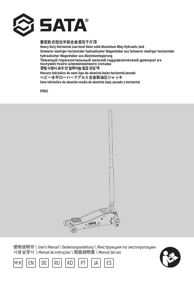
SATA 97821 User manual

铝合金卧式液压千斤顶
Aluminum Alloy Horizontal Hydraulic Jack
Schwerer niedriger horizontaler hydraulischer Wagenheber aus
Aluminiumlegierung
Горизонтальный гидравлический домкрат из алюминиевого сплава
알루미늄 합금 수평식 유압 잭
Macaco hidráulico horizontal da liga de alumínio
アルミ合金製水平油圧ジャッキ
Gato hidráulico horizontal de aleación de aluminio
97821
使用说明书 \ User's Manual \ Bedienungsanleitung \ Инструкция по эксплуатации
사용설명서 \ Manual de instruções \ 取扱説明書 \ Manual del uso
中文 EN DE RU KO PT JA ES


中文 EN DE RU KO PT JA ES
97821
3
铝合金卧式液压千斤顶 1.5 公吨:
编号 额定承重
(KG)净重(KG) 毛重(KG) 最高位(MM) 最低位(MM)产品尺寸
(MM)
97821 1500 19.5 21.0 470 85 715x295x160
开箱后即请检查产品,确保产品完好无损。如果发现有任何部件缺失或损坏,请电话联系世达汽车科技(上海)有限公司。
请记录产品序列号:
注:如果产品没有序列号,请记录购买日期。
请妥善保存本使用说明书:
本使用说明书涉及产品的安全警告、组装、操作、检验、维护和清洁程序等内容,请妥善保管。
请将本千斤顶的序列号(或购买日期)写在本使用说明书的首页,并将本说明书保存在干燥安全之处以备参阅
请在完全理解本说明书内容的基础上,正确使用。

中文 EN DE RU KO PT JA ES
97821
4
本千斤顶已经投保产品责任险:
本千斤顶达到最新颁布的美国工程师协会标准 :ASME PALD--2014 标准。
一、安全警告:
1) 在操作使用前,务必仔细阅读并完全理解使用说明书的全部容。不正确的操作可能导致人员损伤及产品损坏。
2) 每次使用前都要检查千斤顶,如有零部件松动或者损坏,不能使用。
3) 根据车辆重量,选择合适载重吨位的千斤顶。
4) 严禁超载使用千斤顶,否则引起的事故责任不在保险范围之列。
5) 严禁偏载,不能倾斜顶升车辆,否则容易造成危险及损坏千斤顶和车辆。
6) 操作前要将车辆刹车制动、将发动机熄火。
7) 操作前必须确认支撑面为水平硬质面,否则会有危险。
8) 千斤顶只能用于顶升,不能用于支撑,顶升完毕,立即选用匹配的千斤顶支架支撑车辆。
9) 必须小心将千斤顶托盘对准车辆底盘的支撑点再开始顶升操作。
10)顶升操作工程中,不能转动手柄、否则会使回油阀被旋松而导致支撑托盘下降。
11)在操作过程中不能移动车辆。
12)卸载下降时,必须逆时针方向缓慢转动手柄,使车辆缓慢下降。
13)不能在只有千斤顶支撑的情况下,在车辆的上下方或周围进行工作。
14)不能自行拆装或改装本千斤顶。
15)不能自行调节安全阀,否则引起的事故责任不在保险范围之列。
16)操作员在操作时必须佩戴符合国家相关安全规定的防护眼镜和工作手套。
二、产品图示:
图1
托盘
起升臂
提手
托盘垫
注油孔螺丝
(未显示)
万向节
(未显示)
液压泵
后轮
手柄
揿手孔

中文 EN DE RU KO PT JA ES
97821
5
图2
注:产品出厂时油泵内添加的是 15" 机械油,如果需要经常在 0℃以下温度的环境中使用,建议更换 10" 航空液压油。
更换时请将油泵中的原有的 15" 机械油全部放出,再注入 10" 航空液压油,具体操作请见第 5页。
三、安装及操作:
安装手柄:
1)紧固螺丝将上下两节手柄连接安装。
2)旋松手柄上的定位螺丝,将手柄塞进手孔。
3)拧紧定位螺丝,完成手柄安装。
排气:
1)旋松注油孔螺丝,但不要取出螺丝(见图 2)。
2)将手柄塞进手孔(见图 1)。
3)逆时针方向转动手柄(见图 1),打开回油阀。
4)顺时针方向转动手柄,掀压手柄,反复上下快速操作几次将油路内空气排放出去。
5)拧紧注油孔螺丝(见图 2)。
注油:
1)取出注油孔螺丝(见图 2)。
2)对准注油孔,缓慢加注合格的液压油(见图 2),直至离注油孔 0.6cm(注意 :注油时不可压操作手柄)。
3)更换注油孔螺丝并拧紧。
安全阀螺丝(不可自
行打开调节)
万向节
液压泵
注油孔螺丝
螺丝

中文 EN DE RU KO PT JA ES
97821
6
顶升操作:
1)选择安全之地,将车辆停靠在坚固平坦的水平面,将发动机熄火。
2)逆时针方向转动手柄,放低千斤顶。起身臂放至最低位后,顺时针方向转动手柄,关闭回油阀。
3)小心仔细地将千斤顶托盘对准车辆底盘的支撑点(参考车辆厂出厂说明书上指定的起重部位)。
4)压手柄直至千斤顶托盘接触车辆底盘的支撑点(注意 :顶升操作前必须确保千斤顶托盘与车辆底盘支撑点完好贴
合形成上下垂直,否则需要重新定位)。
5)继续压手柄,顶升千斤顶。操作要平稳缓慢,每次压要压到底。
6)当车辆被顶升到位后,将匹配的千斤顶支架放置在合适的位置来支撑车辆(注意 :千斤顶支架需要另外购买,且
应该始终成对使用)。
7)缓慢逆时针方向转动手柄,放低千斤顶直至车辆底盘的支撑点落在成对支架的托架中心,然后再顺时针方向转动
手柄关闭回油阀。
注意:
由于本千斤顶有安全限压装置,故对于限压吨位以上重量的车辆,千斤顶会自行保护,不作顶升
下降操作:
1)清理取出车辆下面的所有工具、零配件等。
2)将千斤顶托盘对准车辆底盘的支撑点。顺时针方向转动手柄,顶升千斤顶,取出千斤顶支架。
3)逆时针方向缓慢转动手柄(确保每次转动不超过半圈),将车辆降至地面。
4)继续逆时针方向转动手柄,直至千斤顶到达最低位。
使用千斤顶支架需要注意:
1)千斤顶支架的额定承重量是指一对支架的承重量,使用千斤顶支架时不能超载。
2)使用前必须确保车辆底盘的支撑点都落在成对支架的托架中心,并确保支架被安全锁定不至打滑。
3)成对支架在使用时必须始终保持同样高度。
4)错误使用千斤顶支架,可能会造成人员危险及车辆损坏。
四、检查、维护和清洁:
1)不能使用已经损坏的千斤顶,以防严重伤害事故。如果发现操作过程有异常的声响或振额,必须维修排除故障后
才可使用。
2)每次使用前,都要进行零部件检查。检查是否有断裂、弯曲变形、松动、缺失的零部件,以及其它影响正常操作
的情况。如有任何问题,都必须解决后,才能使用千斤顶。
3)每次使用前,都要进行功能性检查。如果发现不能正常工作,需要检查是否需要排气、注油等。
4)经常检查,当活塞杆顶端、各横轴处、万向节、滚轮、脚轮等转动传动部位缺少润滑脂(即黄油)时,请及时加注黄油。
5)每隔 3年,至少更换一次液压油。更换液压油程序如下:
a)将千斤顶降至最低位,旋松取出注油孔螺丝。
b)倾倒千斤顶,排出全部的液压油(处理液压油要符合当地法规)。
c)朝上放置千斤顶,对准注油孔,慢慢加注合格的液压油,直至离注油孔 0.6cm。
d)逆时针方向转动手柄,打开回油阀。
e)顺时针方向转动手柄到底,揿压手柄,反复上下快速操作几次排放掉油路内空气。
f)再检查油位,如果需要再次注油。
g)拧紧注油孔螺丝。
h)用干净擦布擦干油迹,然后将千斤顶放置在安全之处。

中文 EN DE RU KO PT JA ES
97821
7
五、常见故障及处理:
故障
症状
额定载重下不能顶升 √ √ √ √
载重下托盘自动下降 √ √
托盘始终不能顶升 √ √
揿压手柄感觉软绵无
力√ √
载重下手柄自动翘起 √
注油孔处漏油 √
可能
的原
因
1. 检查是否
彻底关闭回
油阀;或
2. 油路内可
能有空气。
1. 油路可能
堵塞;或
2. 回油阀没
有彻底关
闭。
可能缺少液
压油。
油路内可能
有空气。
液压油可能
太多。
建议
处理
方案
1. 顺时针方
向转动手柄
到底,关闭
回油阀。
2. 将油路空
气排出。
1. 冲刷油路 :
a. 降至最低
位,关回油
阀。
b.升高托盘。
c. 快速释放
回油阀,并
加力使托盘
快速回位。
2. 顺时针方
向转动手柄
到底,关闭
回油阀。
检查液压油
位,如果
需要进行注
油。
将油路空气
排出。
将油路空气
排出。
检查液压油
位,如果需
要,调整油
量。

中文 EN DE RU KO PT JA ES
97821
8
六、售后服务:
用户在使用过程中,如发现千斤顶不能正常工作,可到世达指定经销商处进行维修,维修收费标准按照世达公司公
布的售后维修价格表执行。
七、零件分解图及零配件清单:
配件编号 序列 零配件品名 数量
97821-01 1 托盘垫 1
97821-02 2 托盘定位螺丝 1
97821-03 3 托盘 1
97821-04 4 托盘座 1
97821-05 5 托盘座下横轴 1
97821-06 6 卡簧(M18)2
97821-07 7 前轮横轴 1
97821-08 8 墙板 2
97821-09 9 轴衬 2
97821-10 10 前轮 2
97821-11 11 垫片 2
97821-12 12 螺母(M12)4
97821-13 13 提手 2
97821-14 14 螺丝(M6x25)4
97821-15 15 垫片 2
97821-16 16 螺丝(M8x25)4
97821-17 17 长连杆 2
97821-18 18 螺丝 4
97821-19 19 横连杆 1
97821-20 20 托盘座上横轴 1
97821-21 21 连接砧块 1

中文 EN DE RU KO PT JA ES
97821
9
配件编号 序列 零配件品名 数量
97821-22 22 起升臂侧板 2
97821-23 23 螺栓 2
97821-24 24 垫片(M10)2
97821-25 25 弹簧垫圈(M10)4
97821-26 26 螺丝(M10x25)8
97821-27 27 螺母(M18)2
97821-28 28 螺丝(M10x35)6
97821-29 29 螺丝(M8x20)2
97821-30 30 垫片(M8)2
97821-31 31 螺丝(M10)2
97821-32 32 后轮 2
97821-33 33 后轮座 2
97821-34 34 垫片(M10)2
97821-35 35 螺丝(M6x25)2
97821-36 36 拉簧 2
97821-37 37 卡簧 2
97821-38 38 短连杆 2
97821-39 39 液压泵 1
97821-40 40 防撞手柄套 1
97821-41 41 上节手柄 1
97821-42 42 下节手柄 1
97821-43 43 定位螺丝 1
97821-44 44 卡簧(M12)1
97821-45 45 滚轮 1
97821-46 46 滚轮轴 1
97821-47 47 揿手孔 1

中文 EN DE RU KO PT JA ES
97821
10
配件编号 序列 零配件品名 数量
97821-48 48 螺栓 2
97821-49 49 横连杆 1
97821-50 50 起升臂横轴 1
97821-51 51 橡胶条 2
97821-52 52 销子(M4x45)1
97821-53 53 液压泵顶头 1
97821-54 54 螺栓 2
97821-55 55 起升臂连接砧块 1
97821-56 56 砧块横轴 1
97821-57 57 万向节 1
97821-58 58 安全阀螺丝 2
97821-59 59 注油孔螺丝 1

中文 EN DE RU KO PT JA ES
97821
11
Aluminum Alloy Horizontal Hydraulic Jack 1.5 MT:
No. Rated load
(kg)
Net weight
(kg)
Gross weight
(kg)
Highest level
(mm)
Lowest level
(mm)
Product
dimensions
(mm)
97821 1500 19.5 21.0 470 85 715x295x160
Please check the product immediately after unpacking to ensure that it is intact. If you discover that any components are lost or
damaged, please contact the Customer Service Department of SATA Automotive Technology (shanghai)Co.,Ltd.
Please record the product serial number:
Note: If no product serial number is available, please record the date of purchase.
Please keep these instructions for future reference:
As these instructions are related to the product's safety precautions and assembly, operation, inspection, maintenance and cleaning
procedures, please keep them safe.
Please record the serial number (or date of purchase)of the jack on the first page of these instructions and keep them in a safe, dry
place for future reference.
Please use the product correctly on the basis of a full understanding of these instructions.

中文 EN DE RU KO PT JA ES
97821
12
This jack is covered by product liability insurance:
This jack complies with the latest version of ASME PALD-2014.
I. Safety precautions:
1)Before operation and use, be sure to carefully read and fully understand all the contents of these instructions. Incorrect operation
may result in personal injury or product damage.
2)Check the jack before each use. Do not use it in case of any loosened or damaged parts.
3)Select the jack with the proper loading capacity (tonnage)according to the gross vehicle weight.
4)Never use the jack in an overloaded state, or else any losses caused by an accident will not be covered by the insurance.
5)Unbalanced loading is not allowed. Never tilt a jacked vehicle as this is likely to result in safety hazards and cause damage to the jack
and vehicle.
6)Brake the vehicle and stop the engine before operation.
7)Always confirm that the support surface is a horizontal hard surface before operation so as to avoid potential hazards.
8)The jack can only be used for jacking and cannot be used for supporting. After jacking, matching jacks shall immediately be used to
support the vehicle.
9)The jack tray shall be carefully aligned with the supporting point of the vehicle chassis before jacking.
10)Never rotate the handle during jacking, as this will cause the oil return valve to become loosened and the supporting tray to fall.
11 )Do not move the vehicle during operation.
12)During unloading and lowering, slowly rotate the handle counterclockwise to lower down the vehicle.
13)Do not work under or around a vehicle which is only supported by a jack.
14)Do not disassemble or modify the jack without permission.
15)Never adjust the safety valve without permission, or else any losses caused by an accident will not be covered by the insurance.
16)During operation, the operator shall wear safety goggles and working gloves conforming to the relevant national safety regulations.
II. Product diagrams:
Figure 1
Tray
Lifting arm
提手
托盘垫
Oil filler screw
(not shown)
Universal joint
(not shown)
Hydraulic pump
Rear wheel
Handle
Handle hole

中文 EN DE RU KO PT JA ES
97821
13
Figure 2
Note: The product contains 15" mechanical when it leaves the factory. If it is to be frequently used in environments below 0 ℃, it is
recommended to use 10" aviation hydraulic oil. Please completely drain the original 15" mechanical oil from the oil pump and add 10"
aviation hydraulic oil. Please refer to page 5 for the specific operation procedure.
III. Installation and operation :
Handle installation :
1)Tighten the screws to connect and install the upper and lower handles.
2)Release the positioning screw on the handle and insert the handle into the handle hole.
3)Tighten the positioning screw to complete handle installation.
Exhaust :
1)Release the oil filler screw but do not remove it (see Figure 2).
2)Insert the handle into the handle hole (see Figure 1).
3)Rotate the handle counterclockwise (see Figure 1)and turn on the oil return valve.
4)Rotate the handle clockwise, lift and press it, and repeat this operation several times quickly to discharge air from the oil circuit.
5)Tighten the oil filler screw (see Figure 2).
Oil filling:
1)Remove the oil filler screw (see Figure 2).
2)Align with the oil filler and slowly add qualified hydraulic oil (see Figure 2)until it is 0.6 cm from the oil filler (note: do not press
the operating handle when adding oil).
3)Replace the oil filler screw and tighten it.
Safety valve screw (cannot be
opened and adjusted by itself)
Universal Joint
Hydraulic pump
Oil filler screw
(not shown)
螺丝

中文 EN DE RU KO PT JA ES
97821
14
Jacking :
1)Park the vehicle on a firm and level surface, and stop the engine.
2)Rotate the handle clockwise and lower the jack. After the lifting arm reaches the lowest position, rotate the handle clockwise and
close the oil return valve.
3)Carefully align the jack tray with the supporting point of the vehicle chassis (refer to the lifting position specified in the operation
instructions provided by the vehicle manufacturer).
4)Press down the handle until the jack tray is in contact with the supporting point of the vehicle chassis (note: before jacking, ensure
that the jack tray and supporting point of the vehicle chassis are properly fitted in order to ensure proper verticality, or else they
must be repositioned).
5)Continue to press the handle and lift the jack. The operation shall be smooth and slow, and the handle shall be pressed to the
furthest position every time.
6)When the vehicle is jacked properly, place the matched jack bracket in a proper position to support the vehicle (note: jack brackets
shall be purchased separately and always used in pairs).
7)Slowly rotate the handle counterclockwise, lower down the jack until the supporting point of the chassis is located in the center of
the paired brackets, and rotate the handle clockwise to close the oil return valve.
Note:
With the safety pressure limit device, the jack will protect vehicles heavier than the pressure limit tonnage from lifting
Lowering:
1)Remove all tools and spare parts from under the vehicle.
2)The jack tray shall be aligned with the supporting point of the vehicle chassis. Rotate the handle clockwise, lift the jack and remove
the jack bracket.
3)Slowly rotate the handle counterclockwise (ensure no more than half a circle each time)and lower the vehicle to the ground.
4)Continue to rotate the handle counterclockwise until the jack reaches the lowest level.
During the use of this jack bracket, it is necessary to pay attention to the following:
1)The rated load of the jack bracket is the combined load of both brackets, and overloading is not allowed during use.
2)The supporting points of the vehicle chassis shall be located in the center of the paired brackets before use, and the brackets shall
be safely locked to prevent slipping.
3)The paired brackets shall always be maintained at the same height during use.
4)Incorrect use of jack bracket may result in personal injury and vehicle damage.
IV. Inspection, maintenance and cleaning:
1)Never use damaged jacks as this could result in severe personal injury. If there is any abnormal sound or vibration during operation,
stop operation and conduct troubleshooting and repairs.
2)All parts shall be checked before each use. Check for broken, bent, deformed, loose or missing parts, or any other conditions that
could affect normal operation. The jack can only be used after all problems are solved.
3)Functionality inspection shall be carried out before each use. If it cannot work normally, check whether venting or oil filling is
required.
4)Check the jack frequently. If the top end of the piston rod, transverse shafts, universal joints, rollers, casters or other rotating parts
lack lubrication (i.e. grease), please add grease immediately.
5)Replace the hydraulic oil at least once every 3 years. The hydraulic oil replacement procedure is as follows:
a)Lower the jack to the lowest level and release and remove the oil filler screw.
b)Overturn the jack and drain out all the hydraulic oil (hydraulic oil shall be disposed of according to the local laws and

中文 EN DE RU KO PT JA ES
97821
15
regulations).
c)Place the jack upwards, align it with the oil filler and slowly fill qualified hydraulic oil until it is 0.6 cm from the oil filler.
d)Rotate the handle counterclockwise and open the oil return valve.
e)Rotate the handle clockwise, lift and press it, and repeat this operation several times quickly to discharge air from the oil circuit.
f)Recheck the oil level and refill the oil if necessary.
g)Tighten the oil filler screw.
h)Wipe it off with a piece of clean cloth, then place the jack in a safe place.
V. Common faults and troubleshooting:
Fault symptoms
symptoms
The jack fails
to rise under
rated load
√√√√
The tray
lowers
automatically
under load
√√
The jack fails
to rise √√
The rolling
handle feels
soft and weak
√√
The handle
tilts
automatically
under load
√
Leakage at
the oil filler √
Possible cause
(s)
1. Check
whether the
oil return valve
is completely
closed;
2. There may
be air in the oil
circuit
1. The oil circuit may be
blocked;
2. The oil return valve is
not completely closed
The amount
of hydraulic
oil may be
insufficient
There
may be
air in the
oil circuit
The amount
of hydraulic
oil may be
excessive

中文 EN DE RU KO PT JA ES
97821
16
Recommended
solutions
1. Rotate
the handle
clockwise to
the furthest
position and
close the oil
return valve;
2. Discharge
the air from
the oil circuit
1. Flush the oil circuit:
a. Drop it to the lowest
level and close the oil
return valve;
b. Lift the tray;
c. Quickly release the oil
return valve andapply
force to make the tray
quickly return to its
original position; or
2. Rotate the handle
clockwise to the furthest
position and close the oil
return valve
Check the
hydraulic
oil level and
add oil if
necessary
Discharge
the air
from the
oil circuit
Check the
hydraulic
oil level and
adjust the
oil quantity
if necessar
VI. After-sales services:
If the operator finds that the jack is not working properly, it can be repaired at a designated SATA dealer. The maintenance fee will be in
accordance with SATA's after-sales maintenance price list.
VII. Exploded view and list of spare parts:
Accessory No. No. Parts No. Quantity
97821-01 1 Tray pad 1
97821-02 2 Tray positioning screw 1
97821-03 3 Tray 1
97821-04 4 Tray seat 1
97821-05 5 Lower transverse shaft of
tray seat 1
97821-06 6 Circlip (M18)2
97821-07 7 Transverse shaft of front
wheel 1
97821-08 8 Wallboard 2

中文 EN DE RU KO PT JA ES
97821
17
Accessory No. No. Parts No. Quantity
97821-09 9 Bushing 2
97821-10 10 Front wheel 2
97821-11 11 Gasket 2
97821-12 12 Nut (M12)4
97821-13 13 Handle 2
97821-14 14 Screw (M6x25)4
97821-15 15 Gasket 2
97821-16 16 Screw (M8x25)4
97821-17 17 Long connecting rod 2
97821-18 18 Screw 4
97821-19 19 Transverse connecting rod 1
97821-20 20 Upper transverse shaft of
tray seat 1
97821-21 21 Connecting anvil block 1
97821-22 22 Lifting arm side plate 2
97821-23 23 Bolt 2
97821-24 24 Gasket (M10)2
97821-25 25 Spring washer (M10)4
97821-26 26 Screw (M10x25)8
97821-27 27 Nut (M18)2
97821-28 28 Screw (M10x35)6
97821-29 29 Screw (M8x20)2
97821-30 30 Gasket (M8)2
97821-26 26 Screw (M10x25)8
97821-27 27 Nut (M18)2

中文 EN DE RU KO PT JA ES
97821
18
Accessory No. No. Parts No. Quantity
97821-28 28 Screw (M10x35)6
97821-29 29 Screw (M8x20)2
97821-30 30 Gasket (M8)2
97821-31 31 Screw (M10)2
97821-32 32 Rear wheel 2
97821-33 33 Rear wheel seat 2
97821-34 34 Gasket (M10)2
97821-35 35 Screw (M6×25)2
97821-36 36 Tension spring 2
97821-37 37 Circlip 2
97821-38 38 Short connecting rod 2
97821-39 39 Hydraulic pump 1
97821-40 40 Anti-collision handle cover 1
97821-41 41 Upper handle 1
97821-42 42 Lower handle 1
97821-43 43 Positioning screw 1
97821-44 44 Circlip (M12)1
97821-45 45 Roller 1
97821-46 46 Roller shaft 1
97821-47 47 Handle hole 1
97821-48 48 Bolt 2
97821-49 49 Transverse connecting rod 1
97821-50 50 Transverse shaft of lifting
arm 1
97821-51 51 Rubber strip 2
97821-52 52 Pin (M4×45)1

中文 EN DE RU KO PT JA ES
97821
19
Accessory No. No. Parts No. Quantity
97821-53 53 Hydraulic pump jack head 1
97821-54 54 Bolt 2
97821-55 55 Lifting arm connecting anvil
block 1
97821-56 56 Transverse shaft of anvil
block 1
97821-57 57 Universal joint 1
97821-58 58 Safety valve screw 2
97821-59 59 Oil filler screw 1

中文 EN DE RU KO PT JA ES
97821
20
Horizontaler hydraulischer Wagenheber aus Aluminiumlegierung 1,5 Tonnen:
Nummer Nennbelastung
(KG)
Nettogewicht
(KG)
Bruttogewicht
(KG)
Höchste
Position
(MM)
Niedrigste
Position
(MM)
Produktgröße
(MM)
97821 1500 19,5 21,0 470 85 715x295x160
Überprüfen Sie das Produkt sofort nach dem Auspacken, um sicherzustellen, dass das Produkt intakt ist. Wenn Teile fehlen oder
beschädigt sind, wenden Sie sich bitte an die Kundendienstabteilung von SATA Automobiltechnologie(Shanghai)GmbH
Bitte notieren Sie die Seriennummer des Produkts:
Hinweis: Wenn das Produkt keine Seriennummer hat, notieren Sie bitte das Kaufdatum.
Bewahren Sie diese Bedienungsanleitung an einem sicheren Ort auf:
Diese Bedienungsanleitung beinhaltet die Sicherheitswarnung, Montage, Betrieb, Inspektion, Wartung und Reinigung des Produkts und
bewahren Sie sie an einem sicheren Ort auf.
Bitte schreiben Sie die Seriennummer (oder das Kaufdatum)dieses Wagenhebers auf die Vorderseite dieser Bedienungsanleitung
und bewahren Sie diese Bedienungsanleitung an einem trockenen und sicheren Ort auf.
Bitte verwenden Sie ihn korrekt, wenn Sie den Inhalt dieser Bedienungsanleitung vollständig verstanden haben.
Table of contents
Languages:
Other SATA Jack manuals