ROHO AGILITY User manual

ROHO®
AGILITY™Back Systems
OPERATION MANUAL
SUPPLIER: This manual must be given to the user of this product.
USER: Before using this product, read instructions and save for
future reference.
shape fitting technology
®
Visit www.therohogroup.com to view the contents of this document in additional languages.
ESPAÑOL: Visite www.therohogroup.com para ver el contenido de este documento en otros idiomas.
FRANÇAIS: Visitez le www.therohogroup.com pour voir le contenu de ce document dans différentes langues.
DEUTSCH: Besuchen Sie www.therohogroup.com, um den Inhalt dieses Dokuments in weiteren Sprachen anzuzeigen.
ITALIANO: Visitare www.therohogroup.com per visualizzare i contenuti del presente documento nelle altre lingue.
NEDERLANDS: Ga naar www.therohogroup.com om de inhoud van dit document in andere talen te bekijken.
DANSK: Besøg www.therohogroup.com for at se indholdet af dette dokument på andre sprog.
SVENSKA: Besök www.therohogroup.com för att visa innehållet i detta dokument i ytterligare språk.
NORSK: Besøk www.therohogroup.com for å se innholdet i dette dokumentet på flere språk.
SUOMI: Käy osoitteessa www.therohogroup.com nähdäksesi tämän asiakirjan sisällön muilla kielillä.
PORTUGUÊS: Visite www.therohogroup.com para exibir o conteúdo deste documento em outros idiomas.


- 1 -
INTENDED USE 2
INFORMATION FOR SAFETY 2-3
PARTS DETAIL 4-5
PRODUCT SPECIFICATIONS 5-6
BACK CANE HARDWARE INSTALLATION AND REMOVAL 7
AGILITY INSTALLATION AND REMOVAL 8-9
FLIP BACK SHELL 9
WIDTH ADJUSTMENT 10
HEIGHT ADJUSTMENT 11
DEPTH AND ANGLE ADJUSTMENT 12
COVER REMOVAL AND INSTALLATION 13
COVER COMPONENTS - REMOVAL AND INSTALLATION 13-14
COVER COMPONENTS - AIR INSERT ADJUSTMENT 15
ACCESSORIES 16
CLEANING AND DISINFECTING 17
MAINTENANCE, DISPOSAL AND TROUBLESHOOTING 18
RETURN POLICY, CONTACT INFORMATION AND LIMITED WARRANTY 19
ESPAÑOL 20
FRANÇAIS 39
TABLE OF CONTENTS
ROHO, Inc. has a policy of continual product improvement and reserves the right to amend this document. The current version of this document is available
at www.therohogroup.com.
ROHO® AGILITY™ Back Systems are manufactured by ROHO, Inc.,
100 North Florida Avenue, Belleville, Illinois 62221-5429
www.therohogroup.com.
© 2012, 2014 ROHO, Inc.
The following are trademarks and registered trademarks of ROHO, Inc.: ROHO®, AGILITY™, and shape fitting technology®.
Zytel®is a registered trademark of DuPont.
Products in this manual may be covered by one or more U.S. and foreign patents and trademarks. For further details please refer to www.therohogroup.com.

- 2 -
INTENDED USE
• DO NOT operate AGILITY without first reading and understanding this manual. If assistance is needed, contact a clinician, ROHO
provider or ROHO, Inc.
• In addition to information in this manual, individuals with an AGILITY installed on a wheelchair must continue to follow the
wheelchair manufacturer’s instructions.
• When using any back system, it is especially important to inspect the skin, especially those areas covering bony prominences,
which are at greater risk for breakdown. If any discoloration (ie. redness, bruising, purple, or darker areas versus normal skin
tone, which may be the beginning sign of skin breakdown) is noted and does NOT disappear within 30 minutes after removal from
the product, discontinue use and consult a healthcare provider immediately.
• AGILITY should be installed by a qualified and competent healthcare professional.
• AGILITY must be sized correctly to the individual and the wheelchair.
• As with any addition to a wheelchair, AGILITY may affect the stability of the wheelchair. Before using an AGILITY, ROHO, Inc.
recommends that a clinician evaluate the need for possible wheelchair modifications.
• DO NOT lean over the top of AGILITY. This may cause a change in center of gravity and the wheelchair could tip over.
• Use caution when installing, adjusting, or removing AGILITY hardware to avoid pinching or trapping fingers in openings.
• AGILITY is not intended for individuals weighing over 300 lbs. (136 kg).
• Check AGILITY screws, clamps, and brackets for wear, breakage, and tightness daily. Retighten loose screws following the
instructions throughout this manual. DO NOT continue to use an AGILITY if any part cannot be tightened or is broken. ROHO, Inc.
recommends that an AGILITY be thoroughly inspected periodically by a qualified technician.
• DO NOT attach, remove or adjust the width of an AGILITY when an individual is seated in the chair.
• DO NOT use an AGILITY to lift or push a wheelchair. Doing so may cause the back system to become unintentionally detached from
the wheelchair. Ensure both left and right safety locks are in the LOCKED ( ) position prior to the individual being seated in the
chair and remain in the LOCKED ( ) position while the individual is seated in the chair.
• AGILITY is compatible with many wheelchairs that are angularly adjustable, recline or tilt and result in a back angle up to and
including 60 degrees. Beyond 60 degrees, AGILITY may not be an appropriate selection. Use with wheelchairs that angularly
adjust, recline or tilt to a back angle greater than 60 degrees may cause AGILITY to accidentally disconnect from the wheelchair,
resulting in a fall and the potential for serious injury. Consult a clinician to determine if AGILITY is compatible with the individual’s
wheelchair.
ROHO®AGILITY™Back Systems (AGILITY) are removable backrest replacement systems for wheelchairs, designed to provide trunk/pelvis
support and positioning to the individual. AGILITY include:
• ROHO®AGILITY™Minimum Contour Back System (AGILITY Minimum Contour)
• ROHO®AGILITY™Mid Contour Back System (AGILITY Mid Contour)
AGILITY have a weight limit of 300 lbs. (136 kg).
ROHO, Inc. recommends that a clinician, such as a doctor or therapist experienced in seating and positioning, be consulted to determine if
an AGILITY is appropriate for the individual’s particular seating needs.
INFORMATION FOR SAFETY - GENERAL WARNINGS
WARNINGS

- 3 -
INFORMATION FOR SAFETY - GENERAL CAUTIONS
• AGILITY is intended to be used with an AGILITY cover, foam pad, lumbar support pad (if applicable), and either the air insert or the foam
insert (if applicable). The air insert and the foam insert are not intended to be used together.
• Protect AGILITY from blunt force shocks that may cause damage and/or breakage.
• Use of any hardware or components, other than those supplied by ROHO, may void the warranty. If replacement parts are needed, contact a
ROHO provider.
• Unless otherwise stated in this manual, AGILITY is not intended to be used with, and has not been tested for use with, other manufacturers’
accessories.
• The components of AGILITY are not intended to be used separately, or in conjunction with, other wheelchair back systems.
• Altering AGILITY may affect its performance and void the warranty.
• Metal components may become hot if exposed to high temperatures or cold if exposed to low temperatures.
• AGILITY may need to be removed from the wheelchair prior to folding the wheelchair.
• The U.S. Environmental Protection Agency, Health Canada, and other government agencies have issued warnings regarding the use of
ozone generators. Prolonged exposure to ozone may degrade some materials used in the manufacture of this product, and may affect the
performance of this product and void the product warranty.
CAUTIONS
• Failure to pay attention to these warnings could result in severe injury to the individual in the wheelchair or to others.
• AGILITY must be correctly and securely installed on the wheelchair following all instructions and warnings provided in this operation
manual.
• AGILITY should be installed on a wheelchair so the individual is seated in an upright position and the wheelchair is facing forward
during transportation in a motor vehicle. AGILITY has only been crash tested on a wheelchair in the forward facing position per the test
information provided above.
• AGILITY must only be used with wheelchairs that comply with the performance requirements of ISO 7176-19 and that are installed, used
and maintained according to the wheelchair manufacturer’s instructions.
• The wheelchair with an AGILITY must be used with an effective wheelchair securement system and a properly positioned, crash-tested
pelvic and shoulder-belt restraint, or Wheelchair Tiedown and Occupant Restraint System (WTORS), following manufacturer’s instructions.
• The top of AGILITY should be positioned as close to the top of the shoulder as possible to provide good support in the event of a crash.
The distance between the top of the user’s shoulder and the top of the back should not exceed 6.5 in. (16.5 cm).
• If an AGILITY is involved in a motor vehicle accident, see MAINTENANCE in this manual.
WARNINGS
For additional information on motor vehicle testing of AGILITY, visit www.therohogroup.com.
CAUTION: Whenever possible, the individual in the wheelchair with an AGILITY should transfer into a manufacturer-installed vehicle
seat and use the vehicle’s crash-tested occupant restraint system.
INFORMATION FOR SAFETY - MOTOR VEHICLE TRANSPORTATION
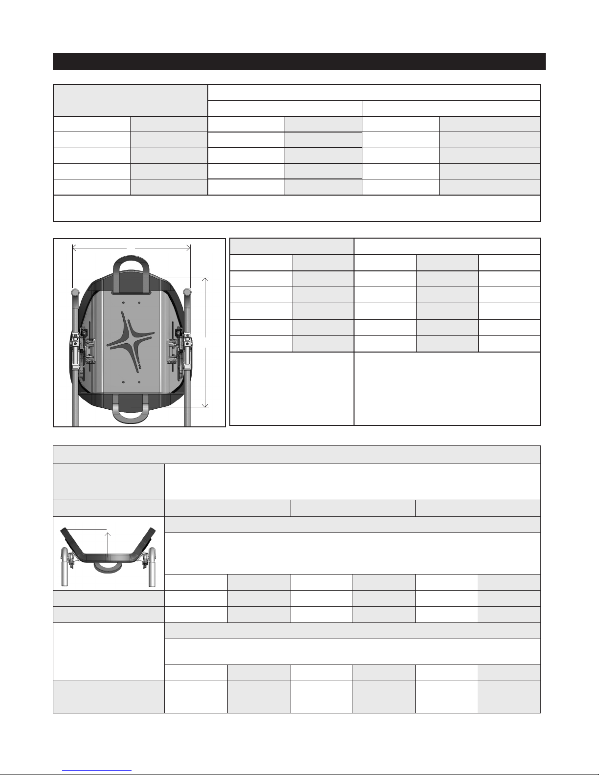
AGILITY with Quick Release Attachment Hardware has been dynamically tested for use in a motor vehicle by a third-party testing facility.
Initial frontal impact test set-up included:
• AGILITY 20 in. (51 cm) in height
• Surrogate: ISO/RESNA wheelchair frame (SWCF); metal seat;
four-point, strap-type tie-down; and SWCF-anchored three-
point belt
• Hybrid III mid-size male seated facing forward and torso
upright
Additional testing with AGILITY positioned 6.5 in. (16.5 cm) below the
shoulders included:
• AGILITY 13 in. (33 cm) in height
• Surrogate: SWCF @ 18” with metal pan; SWTORS;
and WC-anchored lap belt
• Back cane hardware mounted both behind and in front of the back
canes during separate test set-ups
Testing, as described above, concluded that AGILITY meets all criteria for wheelchair seating systems proposed in Section 5.1.1 of
Section 20 ANSI/RESNA/ WC/Volume 4 “Wheelchair Seating Systems for Use in Motor Vehicles”.

- 4 -
PARTS DETAIL
Package Contents:
Hand PumpRepair Kit Lumbar Support Pad
Additional Package Contents depending on model:
Note: A tape measure or ruler is recommended, but not
included in the package contents.
1 65432
Dual Wrench Detail - To separate and assemble for use as an Allen Wrench:
Upper Pin
Back Cane Bracket
(Right ( R), Standard
shown)
Lower Pin
Back Cane
Hardware Bolt
Adjustment
Cylinder
Back Cane Hardware Detail - Right ( R), Standard shown:
Pivoting
Back Cane
Band
Triangle
Bracket
Width and Height
Adjustment Nut Latch
Back Shell Hardware Detail - Right (R) shown:
Depth
and Angle
Adjustment
Bolt
Double Hook -
Right (R)
shown
Safety Lock
Sliding
Height
Adjustment
Bar
(on front side
of back shell)
Width and
Height
Adjustment
Bolt
Width and
Height
Adjustment Bolt
Width and Height
Adjustment Nut
Cover
(See Detail)
Back Shell
Back Shell
Hardware (R)
(See Detail)
Registration Card
Product
Registration Card
Operation Manual
ROHO®
AGILITY™Back Systems
OPERATIONMANUAL
SUPPLIER:This manual must be given to the user of this product.
USER:Before using this product, read instructions and save for
futurereference.
shape fitting technology
®
Dual Wrench (See Detail)
(4 mm Hex Key) (10 mm Box End)
Back Shell Hardware (L)
Back Cane Hardware (See Detail)
LR

- 5 -
To order replacement parts: In the U.S.A., contact the ROHO Customer Service Department, call your product provider or visit
www.therohostore.com. Outside the U.S.A., contact your country’s ROHO International distributor.
PARTS DETAIL CONTINUED
PRODUCT SPECIFICATIONS*
Cover Components Detail:
*Note: The air insert and the foam insert are not intended to be used together.
Cover with Foam Pad only
Foam Pad
Cover
Zipper
Handle
Handle
Air Insert
Foam Pad
Cutout area
for air insert
or foam
insert
Valve Hose Zipper
Cover
Foam Insert
Cover with Foam Pad + Air Insert or Foam Insert*
Fastener
Strip
Handle
Handle
-OR-
-OR-
BACK CANE BRACKET COMPATIBILITY
Back Cane Bracket
(Top View)
Adjusts to Fit Back Cane Diameters (A)
Smallest Largest
in. (cm) in. (cm)
Standard
Fits Circular
Back Canes
0.75 (2.0) 1.0 (2.5)
A
A
*NOTE: All measurements are approximate.
WARNINGS:
AGILITY is compatible with many wheelchairs that are angularly adjustable, recline or tilt and result in a back angle up to and
including 60 degrees. Beyond 60 degrees, AGILITY may not be an appropriate selection. Use with wheelchairs that angularly adjust,
recline or tilt to a back angle greater than 60 degrees may cause AGILITY to accidentally disconnect from the wheelchair, resulting
in a fall and the potential for serious injury. Consult a clinician to determine if AGILITY is compatible with the individual’s wheelchair.
Rigidizer bars may pose a mounting challenge. See TROUBLESHOOTING. Make sure the rigidizer bar does not interfere with any of
the back cane hardware components.
Note: If the back cane brackets are installed on the front side of the back canes, there will be up to 1 in. (2.5 cm) of additional seat depth loss.
Materials:
Cover:
Front Side: Polyester
Back Side: Polyurethane foam coated
nylon/polyurethane coated polyester
Flaps: Polyurethane-coated polyester
Lumbar Support Pad: Polyurethane
Foam Pad:
Front Side: Polyurethane
Back Side: Polyethylene
Foam Insert: Polyurethane
Air Insert:
Front Side: Polyether polyurethane
Back Side: Urethane film coated nylon
Back Shell: Aluminum
Back Shell Hardware: Zytel®
Sliding Height Adjustment Bar: Aluminum
Back Cane Hardware:
Back Cane Bracket: Aluminum
Pivoting Cane Band and Adjustment
Cylinder: Steel
AGILITY complies with CAL 117, EN 1021-1 and EN 1021-2 flammability requirements.
Wheelchair Compatibility:
AGILITY is designed to be used with most wheelchairs that have back canes described in the BACK CANE BRACKET COMPATIBILITY chart.
AGILITY must be sized correctly to the wheelchair and may not fit every wheelchair. Consult with the provider or clinician providing your
equipment to determine if your wheelchair and back canes are compatible with AGILITY.

- 6 -
PRODUCT SPECIFICATIONS* CONTINUED
AGILITY HEIGHT (H) ADJUSTABLE AIR INSERT HEIGHT
in. (cm) in. (cm) # Cells
10.0 (25.5) 6.5 (16.5) 3
13.0 (33.0) 10.5 (27.0) 5
16.0 (40.5) 12.5 (32.0) 6
18.0 (45.5) 14.5 (37.0) 7
20.0 (51.0) 16.5 (42.0) 8
Height (H) measurements are
taken from center edge to center
edge between the narrow and
wide ends of the back shell.
Note: Cover assembly not
included in height measurement.
All air inserts:
• Width: 3 cells, 6.5 in. (16.5 cm)
• Perimeter: 0.25 in. (1.0 cm) included in height
and width measurements
• Cell height: 1.25 in. (3.0 cm) when fully inflated
W
H
*NOTE: All measurements are approximate.
AGILITY
WIDTH (W)
ADJUSTS TO FIT WHEELCHAIR WIDTHS
Smallest** Largest
in. (cm) in. (cm) in. (cm)
14.0 (35.5) 13.0 (33.0) 14.0 (35.5)
16.0 (40.5) 15.0 (38.0) 16.0 (40.5)
18.0 (45.5) 17.0 (43.0) 18.0 (45.5)
20.0 (51.0) 19.0 (48.5) 20.0 (51.0)
Width (W) measurements are taken from the outside of the back cane to the outside of the back cane.
**There will be a 0.5 in. (1.5 cm) loss of seat depth if an AGILITY is fitted to the smallest wheelchair width within each size range.
AGILITY DEPTH (D) AND WEIGHT RANGE
AGILITY Model Depths and weights are based on (W x H): 14 in. x 10 in. (35.5 cm x 25.5 cm), 16 in. x 16 in. (40.5 cm x 40.5 cm),
and 20 in. x 18 in. (51.0 cm x 45.5 cm) AGILITY Minimum Contour models. 14 in. x 10 in. (35.5 cm x 25.5 cm),
16 in. x 16 in. (40.5 cm x 40.5 cm), and 20 in. x 20 in. (51.0 cm x 51.0 cm) AGILITY Mid Contour models.
Least Average Greatest
DEPTH
Depth (D) measurements are taken from the highest point of a contoured edge of the cover to the center,
front surface of a cover assembled with an air insert inflated to allow 0.5 in. (2.5 cm) immersion. Depth of
foam only models will be 0.5 in. (2.5 cm) less.
in. (cm) in. (cm) in. (cm)
AGILITY Minimum Contour 3.0 (7.5) 3.0 (7.5) 3.5 (9.0)
AGILITY Mid Contour 3.75 (9.0) 4.0 (10.0) 4.25 (11.0)
WEIGHT
Weight ranges do not include Back Cane Hardware. Pair of Back Cane Hardware with Standard Bracket:
0.75 lbs. (0.30 kg)
lbs. (kg) lbs. (kg) lbs. (kg)
AGILITY Minimum Contour 2.5 (1.1) 4.0 (1.8) 5.25 (2.3)
AGILITY Mid Contour 2.5 (1.2) 4.25 (1.9) 6.0 (2.8)
D

- 7 -
Tighten the back cane hardware bolts with the Allen
wrench until snug + one-quarter turn. Note: If
torque wrench available, tighten to no more than 40
inch-pounds (4.5 Newton-meters).
Hold the pivoting back cane band against the
back cane and tighten back cane hardware
bolt by hand until the adjustment cylinder is
pulled forward against back cane.
(Repeat steps 1 to 5 for opposite back cane
hardware.)
Hold the pivoting back cane band against the
back cane and rotate the back cane bracket to
press against the back cane.
Push against the back cane hardware bolt
with thumb and clip the opening of the
pivoting back cane band around the end of the
adjustment cylinder. Position the narrow end
of the cane band’s opening into the groove at
the end of the adjustment cylinder.
Press the end of the adjustment cylinder and
unclip the pivoting back cane band. Rotate
the back cane bracket away from the back
cane band.
Loosen the back cane hardware bolt as shown.
Note: The bolt should NOT disengage from the
adjustment cylinder.
BACK CANE HARDWARE INSTALLATION
Notes: The existing wheelchair back should be removed from the wheelchair following the wheelchair/wheelchair back manufacturer’s directions.
Make sure the wheelchair back canes are clean before installing the back cane hardware.
Apply wheelchair brakes before installing back cane hardware.
Back cane hardware is pre-assembled as left (L) and right ( R). For demonstration purposes, only left (L) assembly may be shown below.
Rotate the back cane bracket away from the
back cane.
BACK CANE HARDWARE REMOVAL
WARNING: DO NOT install AGILITY back cane hardware with the individual in the chair.
WARNING: DO NOT remove AGILITY or the back cane hardware with the individual in the chair.
Push against the back cane hardware bolt
with thumb and pry pivoting back cane band
away from adjustment cylinder groove.
Note: Remove the AGILITY from the wheelchair prior to removing the back cane hardware. SEE AGILITY REMOVAL.
1 2 3
46
5
1 2 3
Loosen the back cane hardware bolt as shown.
Note: The bolt should NOT disengage from the
adjustment cylinder.
LR
IMPORTANT! Make sure the upper and lower
pins of each back cane bracket are aligned with each
other, both brackets are installed on the correct side,
and the height of both brackets is equal.

- 8 -
Tilt the back shell toward the back canes until
the latches rest on upper pins.
Slightly lift the back shell up then tilt it
backwards toward the back canes. Note: DO
NOT lift the back shell up so far that the lower
ends of the double hooks clear the lower pins.
Lower ends of the double hooks should remain
positioned over the lower pins.
Hook the lower ends of double hooks onto the
lower pins of the back cane brackets.
Tilt the top of the back shell toward the front
of the chair.
WARNING: DO NOT attach the AGILITY with the individual seated in the wheelchair.
Lock the latches by pushing both the left and
right safety locks toward the center of the
back shell into the LOCKED ( ) position.
AGILITY INSTALLATION
Note: Safety locks must be in the UNLOCKED ( ) position to the install the AGILITY.
WARNING: Make sure both left
and right safety locks are in the
LOCKED ( ) position prior to the
individual being seated in the chair.
To test locks, use the handle to pull
up on AGILITY.
DO NOT use the handle to pull the wheelchair with the individual seated in the wheelchair. The handle is intended only to assist
with the installation and removal of AGILITY from the wheelchair.
Ensure both left and right safety locks are in the LOCKED ( ) position prior to the individual being seated in the chair and
remain in the LOCKED ( ) position while the individual is seated in the chair.
Once installation is complete, make sure all hardware is securely tightened prior to the individual being seated. Refer to
appropriate sections in this manual for recommended torque specifications. If adjustments are needed, have individual
transfer out of the chair if required, adjust as necessary, and re-tighten all hardware prior to the individual being seated.
WARNINGS:
1
654
32
Push down on the back shell until the mouths
of the latches open and the upper ends of
double hooks wrap around the upper pins.
Latches should now be all the way down in the
closed position.
IMPORTANT! Make sure both latches are
fully closed. If latches will not close, or
back shell hardware will not hook to the upper
and lower pins of the back cane bracket, see
TROUBLESHOOTING.

- 9 -
ROHO, Inc. recommends that the bottom portion of an AGILITY be
positioned to make contact at the PSIS for optimal pelvic support and
trunk control.
Use the top handle to slightly lift the AGILITY
up and remove it from the wheelchair.
Open the left and right latches by pulling
the latches up.
UNLOCK ( ) the safety locks.
AGILITY REMOVAL
WARNING: DO NOT remove the AGILITY with the individual seated in the wheelchair.
WARNING: If the AGILITY is not positioned to make contact at the PSIS,
pelvic support and trunk control may be reduced.
Posterior, Superior, Illiac Spine (PSIS):
1 2 3
Rotate the back shell to wide or narrow top.Remove the nuts at the end of the width and
height adjustment bolts with the box end
wrench. Detach the triangle brackets from the
back shell.
Note: AGILITY must be removed from the wheelchair before flipping positions.
FLIP BACK SHELL
321
See all ADJUSTMENT and INSTALLATION
sections in this manual.
AGILITY INSTALLATION CONTINUED
PSIS PSIS

- 10 -
WIDTH ADJUSTMENT
See WIDTH ADJUSTMENT WARNINGS at the top of this page.
Remove AGILITY from the wheelchair before adjusting the width.
Remove the nuts at the end of the width and height adjustment
bolts with the box end wrench. Detach the triangle brackets from
the back shell.
Refer to the AGILITY Sizing Guide to determine which grooves on
the top and bottom of the triangle brackets match the desired
AGILITY width position. At the desired groove location, slide the
triangle bracket horizontal slots over the flat end of the width and
height adjustment bolts.
Tighten the nuts on the width and height adjustment bolts with
the box end wrench until snug + one-quarter turn. Note: If torque
wrench available, tighten to 42 +/- 2 inch-pounds (4.75 +/- 0.25
Newton-meters).
Replace the nuts on the width and height adjustment bolts. With
the left (L) and right (R) back shell hardware positioned at equal
heights, tighten the nuts so they are snug enough to hold the
hardware in place. Use the box end wrench if necessary.
If height adjustment is needed, proceed to HEIGHT ADJUSTMENT
section.
WARNING: Once adjustment is complete, make sure all
hardware is securely tightened before the individual is
seated in the wheelchair.
WARNINGS: DO NOT remove the AGILITY with the individual in the chair.
DO NOT adjust the width of an AGILITY with the individual in the chair.
1
4
2
3
Install AGILITY on the wheelchair. See AGILITY INSTALLATION.
5
IMPORTANT! Use the reference grooves on the triangle
brackets to make sure that the width and height adjustment
bolts are in the same position within the horizontal slots in the
triangle brackets.

- 11 -
Loosen the nuts on the width and height adjustment bolts with
the box end wrench.
HEIGHT ADJUSTMENT
Tighten the nuts on the width and height adjustments bolts with
the box end wrench until snug + one-quarter turn. Note: If
torque wrench available, tighten to 42 +/- 2 inch-pounds (4.75
+/- 0.25 Newton-meters).
Slide the back shell up and down in the vertical slots until the
desired height is achieved.
WARNING: Once adjustment is complete, make sure all
hardware is securely tightened.
4
3
21
Install the AGILITY on the wheelchair. See AGILITY
INSTALLATION. The individual may be seated in the chair. See
HEIGHT ADJUSTMENT WARNING at the top of this page.
WARNING: Height adjustments can be made with the individual in the chair if performed with caution. Make sure wheelchair wheels are
locked, AGILITY safety locks are in the LOCKED ( ) position, and all hardware is securely tightened before the individual is seated in
the chair.
IMPORTANT! In the sliding height adjustment bar, count
the number of square slots that are visible through the
vertical slots in the back shell to make sure that the left (L)
and right (R) back shell hardware are in the same position.

- 12 -
TO ADJUST THE ANGLE: Pivot the back shell
back and forth until desired incline or decline
is achieved.
See WARNINGS at the top of this page.
Loosen the left and right depth and angle
adjustment bolts with the Allen wrench:
• 2 to 3 full rotations TO ADJUST THE SEAT
DEPTH
• 1 to 2 full rotations TO ADJUST THE ANGLE
only
DEPTH AND ANGLE ADJUSTMENT
TO ADJUST THE SEAT DEPTH: Slide the back
shell forward or backward to the desired
depth. Note: If triangle bracket will not slide,
see TROUBLESHOOTING.
WARNINGS:
Depth and angle adjustments can be made with the individual in the chair, if performed correctly and with caution. If the installer
finds it too difficult or unsafe to make depth and angle adjustments with the individual in the chair, have the individual transfer
safely out of the chair.
Make sure the wheelchair wheels are locked, the AGILITY safety locks are in the LOCKED ( ) position, and all hardware is tight
before the individual is seated in the chair.
DO NOT rotate the depth and angle adjustment bolts more than three (3) full rotations. If the depth and angle adjustment bolts are
over-rotated, components of the back shell hardware will begin to disassemble, preventing the bolt from being tightened securely.
Transfer the individual out of the chair immediately if over-rotation of the bolt occurs. Contact ROHO, Inc. for instruction on
re-assembly of the back shell hardware. See CONTACT INFORMATION.
WARNING: Once depth and angle adjustment is complete, make sure all hardware is securely tightened. Refer to appropriate
sections in this manual for recommended torque specifications. If individual is seated in the chair and depth and angle
re-adjustments are needed, see WARNINGS at the beginning of this section and re-adjust as necessary. Re-tighten all hardware
securely.
3
21
Note: AGILITY must be installed on the wheelchair before adjusting the seat depth and angle.
Hold the back shell in position. Tighten right
and left depth and angle adjustment bolts with
the Allen wrench until snug + one-quarter turn.
Note: If torque wrench available, tighten to 60
+/- 4 inch-pounds (7 +/- 0.5 Newton-meters).
4
IMPORTANT! Make sure the depth
positions on the left and right sides are
equal by comparing the markers on the top of
the triangle brackets.
IMPORTANT! Make sure the left (L) and
right (R) double hooks are rotated to the
same angle by comparing the markers on the
front of the double hooks.

- 13 -
COVER COMPONENTS - REMOVAL
Beginning at the wide end, pull the cover
away from the back shell releasing it from
the fastener strips on the front side of the
back shell.
On the back side of the back shell’s wide end,
release the fastener strips between the cover
flap and the back shell.
Flip the cover completely over the narrow end
of back shell.
On the front of the back shell’s narrow end,
release the fastener strips between the cover
flap and the back shell.
Pull the flap from the horizontal slot in the
back shell.
COVER REMOVAL AND INSTALLATION
TO REMOVE THE COVER:
TO REMOVE THE FOAM PAD, AIR INSERT OR FOAM INSERT:
WARNING: DO NOT remove or install the AGILITY cover with the individual in the chair.
DO NOT use the AGILITY without the cover, foam pad, and, if applicable, the air insert or foam insert, in place.
1 2
TO INSTALL THE COVER:
3
1. Unzip the cover.
2. Remove the foam pad from inside the cover with the air insert or foam insert, if applicable, still attached.
3. Detach the insert from the fastener strip in the cutout area of the foam pad.
4. If the air insert attached, pull the valve hose back through the hole in the foam pad.
From the back side of the back shell, push
the flap through the horizontal slot on back
shell’s narrow end.
Press fastener strips on the flap and back
shell together.
Flip the cover over the narrow end of the back
shell.
Make sure the zipper side of the cover is
toward the back shell.
Secure the back side of the cover to the
fastener strips on the front side of the back
shell.
Pull the wide end of the cover over the wide
edge of the back shell.
Press the fastener strips on the cover flap and
back shell’s wide end together.
1 2 3

- 14 -
COVER COMPONENTS - INSTALLATION
TO INSTALL THE FOAM PAD:
TO INSTALL THE FOAM PAD WITH AIR INSERT:
With the fabric back of the air insert facing
the cutout area of the foam pad, align the air
insert’s valve hose with the hole in the corner
of the cutout area. Slide the air insert’s valve
hose through the hole.
Place the air insert into the cutout area of the
foam pad.
Secure the fabric back of the air insert to the
fastener strip in the cutout area of the foam
pad.
Tuck the perimeter of the air insert between
the foam layers just around the edge of the
cutout area.
Unzip the cover and place the foam pad with
the air insert attached inside the cover.
Note: The air insert should be facing the front
of the cover. The wide and narrow ends of the
foam pad should be aligned with the wide and
narrow ends of the cover.
1. Unzip the cover and place the foam pad into the cover.
Note: The wide and narrow ends of the foam pad should be aligned with the wide and narrow ends of the cover.
2. Zip the cover closed.
3. Install the cover on the back shell.
1 2 3
45a
a. If adjustment of the air insert is NOT
needed:
Place the valve hose inside the zipper area.
Zip the cover closed.
Install the cover on the back shell.
b. If adjustment of the air insert is needed:
Partially zip the cover closed allowing access
to the valve.
Install the cover on the back shell.
See TO ADJUST THE AIR INSERT.
5b
TO INSTALL THE FOAM PAD WITH FOAM INSERT:
1. Align the fastener strip on the back of foam insert with the fastener strip in the cutout area on the front of foam pad and press together to
secure in place.
2. Unzip the cover and place the foam pad with the foam insert attached into the cover.
Note: The side of the foam pad with the foam insert should face the front of the cover. The wide and narrow ends of the foam pad should be
aligned with the wide and narrow ends of the cover.
3. Zip the cover closed.
4. Install the cover on the back shell.

- 15 -
COVER COMPONENTS - AIR INSERT ADJUSTMENT
Notes: Before adjusting the air insert, the cover with the foam pad and air insert must be correctly installed on the back shell.
AGILITY must be correctly installed and adjusted on the wheelchair.
Slide the pump’s nozzle over the valve and turn the valve
counterclockwise to open.
Inflate the air insert until the cells arch.
The individual may be seated in the wheelchair in their
normal position.
Turn the valve counterclockwise to release air until the
individual is comfortable.
Turn the valve clockwise to close.
Pinch the pump’s nozzle and turn the valve clockwise to
close.
Remove the pump.
Detach the flap closest to the zipper.
Place the valve hose inside the zipper.
Zip the cover closed and reattach the flap.
• CHECK INFLATION AT LEAST ONCE A DAY!
• The air insert must be used with the air cells facing the front of
the wheelchair.
• The individual’s comfort level may be reduced if the air insert is:
• not positioned correctly
• not properly sized to the foam pad
• under-inflated or over-inflated
• If the air insert does not appear to be holding air, see
TROUBLESHOOTING. If the air insert is still not holding air, replace
the air insert with the foam insert and contact ROHO, Inc. or your
international distributor. See CONTACT INFORMATION.
• Changes in altitude may require adjustment to the air insert.
Check the inflation level of the air insert when changing altitude.
• Keep the air insert away from sharp objects which may puncture
the air cells and cause it to deflate.
CAUTIONS
TO ADJUST THE AIR INSERT:
• If the air insert has been in temperatures less than 32°F / 0°C and
exhibits unusual stiffness, allow the air insert to warm to room
temperature, then open corner air valve. Roll up the air insert
and then unroll it until the polyurethane is soft and pliable again.
Repeat adjustment instructions before using.
• DO NOT:
• use the air insert as a seat cushion.
• expose the air insert to high heat, open flames or hot ashes.
• use the valve as a handle to carry or pull the air insert.
• use the air insert as a water flotation device (e.g., a Life
Preserver).
• use both the air insert and the foam insert together.
• use a pump, cover, foam pad or repair kit, other than those
provided by ROHO, Inc., with an air insert Doing so may void the
product’s warranty.
3
21
WARNING: Safely transfer the individual out of the wheelchair.WARNING: Safely transfer the individual into the wheelchair.
4

- 16 -
ACCESSORIES
LUMBAR SUPPORT PAD:
The Lumbar Support Pad provides added support to the lumbar region. (Not included with all models.)
Package contents include hook and loop fastener strips. The hook side of the fastener strip is pre-attached to the back of the Lumbar Support
Pad.
DO NOT install a headrest to an AGILITY with the individual in the chair.
Pay attention to all WARNINGS and CAUTIONS listed in the AGILITY Back Systems Operation Manual when installing
another manufacturer’s headrest.
AGILITY has not been tested with a third-party headrest installed. If a headrest is necessary, follow the headrest
manufacturer’s instructions and safety information.
HEADREST:
To Install a Headrest, refer to the manufacturer’s product information and instructions supplied with headrest.
Note: Before installing another manufacturer’s headrest, consult with a clinician or service provider to ensure the headrest is
compatible with AGILITY.
Pre-drilled holes for attaching a universal headrest mount.
Note: Pre-drilled holes not available on AGILITY models 10 in. (25.5 cm) in height.
WARNINGS:
To Install a Lumbar Support Pad:
1. Detach the cover flap closest to the zipper and unzip the cover.
2. Place the lumbar support inside the cover positioned at the curve of the spine, or where it is most comfortable.
Notes: The Lumbar Support may be placed either in front of or in back of the foam pad.
Placement behind the foam pad is recommended for models with the air insert.
Placement in front of the air insert may reduce the performance of the air insert.
3. Remove the backing from the loop side of the fastener strip and secure the lumbar support pad in the desired position.
Note: If the loop fastener strip is attached to the inside of the cover, the fastener strip may need to be replaced after multiple cover
washings.
4. Zip the cover closed and re-attach the cover flap.
To Remove a Lumbar Support Pad:
1. Detach the cover flap closest to the zipper and unzip the cover.
2. Carefully detach the hook and loop fastener strips from each other.
Refer to the product information included in the package with other ROHO accessories.
OTHER ACCESSORIES:
Altering an AGILITY, including, but not limited to, drilling additional holes, to install another manufacturer’s headrest
may void the AGILITY warranty.
CAUTION:

- 17 -
CLEANING AND DISINFECTING
Cleaning and disinfecting are two separate processes. Cleaning MUST precede disinfection.
Note: Product MUST be cleaned, disinfected, and checked for proper functioning between use by different individuals.
CAUTION: DO NOT use abrasives such as steel wool or scouring pads on components of AGILITY.
DO NOT use cleaning products containing petroleum or organic solvents [i.e. acetone, toluene,
Methyl Ethyl Ketone (MEK), naphtha, dry cleaning fluids, adhesive removers] on components of AGILITY.
WARNING: If instructed to use bleach, follow safety guidelines on bleach container.
AGILITY Component To Clean: To Disinfect:
Back shell, back shell hardware
and back cane hardware:
Hand wash in warm (40°C) water with soap and a
sponge. Rinse with clean water. Wipe dry with a
clean cloth and then allow to air dry completely.
Wipe gently with a cloth dampened with a
household disinfectant. Rinse with clean water.
Wipe dry with a clean cloth and then allow to air
dry completely.
Cover:
Notes: Remove the foam and
air components from the cover
prior to cleaning and disinfecting.
Secure the hook and loop fastener
strip on the handle at the wide
end of the cover.
Turn the cover inside out.
Zip the cover closed to avoid
snags.
Machine wash in warm (40°C) water with mild
detergent. Tumble dry low.
Hand wash in warm (40°C) water using 1 part
household liquid bleach per 9 parts water. Rinse
thoroughly with clean water. The cover may also
be machine washed in hot (60°C) water to
disinfect. Tumble dry low.
Foam pad, foam insert and
lumbar support pad:
Note: Remove the foam
components from the cover prior
to cleaning.
Note: Disinfectants are NOT effective on porous
surfaces such as foam. Replace soiled or
contaminated foam components with authorized
ROHO foam components only. Replacement foam
components may be purchased separately. Soiled
or contaminated foam components MUST NOT be
used by different individuals.
Wipe lightly with a damp cloth. DO NOT use soap.
DO NOT submerge in water. Wipe off with a clean
cloth. Completely air dry before replacing in cover.
Air insert:
Notes: Remove the air
insert from the cover and foam
pad prior to cleaning and
disinfecting.
Make sure the valve is closed.
DO NOT allow water or cleaning
solution to enter the air insert.
Place in large sink or basin with warm (40°C)
water. ROHO, Inc. recommends using a mild
hand-washing or dish-washing liquid, laundry
detergent, or other multipurpose detergents used
for general cleaning. Use a soft, plastic bristle
brush, sponge, or washcloth to gently scrub all
cushion surfaces. Rinse with clean water. Air dry.
DO NOT machine wash or dry. DO NOT expose to
direct sunlight.
Hand wash in warm (40°C) water using 1 part
household liquid bleach per 9 parts water. Rinse
thoroughly with clean water. Air dry. DO NOT
machine wash or dry. DO NOT autoclave.
= Wipe with damp cloth
1:9
+
1:9
or
+

- 18 -
DISPOSAL
When properly used and disposed of, there are no known environmental hazards associated with the components of the product in this manual.
Dispose of the product and/or components in accordance with the applicable regulations in your jurisdiction. DO NOT INCINERATE.
Check AGILITY screws, clamps, and brackets for wear, breakage, and tightness daily. Retighten loose screws following instructions throughout
this manual.
WARNING: DO NOT continue to use an AGILITY if any part cannot be tightened or is broken. ROHO, Inc. recommends that an AGILITY be
thoroughly inspected periodically by a qualified technician.
Problem installing or adjusting AGILITY, check the following:
BACK CANE HARDWARE INSTALLATION:
1. Make sure that both the left (L) and right ( R) back cane brackets are in line with the frame of wheelchair and are not twisted.
2. Make sure that the heights of both the left (L) and right ( R) back cane brackets are equal. Use a tape measure or ruler, if necessary.
3. The normal installation location of the back cane brackets is on the back side of the back canes. If a rigidizer bar interferes with the back
cane brackets installed in the normal location, the back cane brackets may be installed on the front side of the back canes. In either
orientation, the left ( ) and right ( ) directional markers on the back cane brackets should be correctly located from the
viewpoint of the installer.
AGILITY INSTALLATION:
1. Make sure that both the left (L) and right ( R) back cane brackets are in line with the frame of wheelchair and are not twisted.
2. Make sure that the width is set appropriately for the chair. Back cane widths may vary. Back shell hardware is factory installed to
accommodate most wheelchairs. If back shell hardware will not hook to the upper and lower pins of the back cane brackets, or if latches
will not close, a width adjustment may be needed. Adjust the width as described in WIDTH AND HEIGHT ADJUSTMENT. It may take a few
attempts to find the ideal width position for your chair.
3. If latches will not close, check to see if safety locks are in the LOCKED ( ) position. Safety locks should be in the UNLOCKED ( )
position to install AGILITY, and then LOCKED ( ) prior to the individual being seated in the chair.
WIDTH AND HEIGHT ADJUSTMENT:
1. Make sure the left (L) and right (R) back shell hardware are on the correct side.
2. Make sure the width and height adjustment bolts are positioned the same within the horizontal slots in the triangle brackets. Use the
reference grooves above and below the horizontal slots on the triangle brackets as guides.
3. Make sure the left (L) and right (R) back shell hardware are positioned the same in the vertical slots on the back shell. Count the number of
square slots in the sliding height adjustment bar that are visible through the vertical slots in the back shell.
DEPTH AND ANGLE ADJUSTMENT:
1. If a triangle bracket will not slide, make sure the slider nut is not in position to interfere.
Adjust slider nut position if necessary.
2. Make sure that the left (L) and right (R) depths are equal. Compare the markers on the top of the triangle brackets.
3. Make sure that the left (L) and right (R) double hooks are rotated to the same angle. Compare the markers on the front of both double hooks.
Problem with the air insert, check the following:
1. If the air insert is not holding air, make sure the valve is tightly closed by turning the valve clockwise. If still not holding air, visibly check for
holes. If no holes are visible, close the valve and immerse the air insert in a sink or tub of water and look for air bubbles. If ‘pin-hole,’ sized
holes are found, air dry the insert completely and then use the repair kit that came with the product and follow the repair kit
instructions. If large holes or other leaks are found, see LIMITED WARRANTY Section.
2. If the air insert is not comfortable, add or remove air to adjust to your comfort level. (see TO ADJUST THE AIR INSERT). Make sure air cells are
facing the front of the wheelchair and the cover is properly positioned (see TO INSTALL THE COVER and TO INSTALL THE FOAM PAD WITH AIR
INSERT).
3. If the air insert slides inside the cover, make sure it is properly positioned and the fabric back is secured to the fastener strip in the cutout
area of the foam pad (see TO INSTALL THE FOAM PAD WITH AIR INSERT). The perimeter of the air insert should be tucked in between the foam
layers around the edge of the cutout area.
TROUBLESHOOTING
MAINTENANCE
L R
Other manuals for AGILITY
2
Table of contents
Other ROHO Wheelchair manuals

ROHO
ROHO AirLITE User manual

ROHO
ROHO Hybrid Elite User manual

ROHO
ROHO AirLITE User manual

ROHO
ROHO AGILITY AG-LATSA-M-FL User manual

ROHO
ROHO JetStream Pro User manual

ROHO
ROHO DRY FLOATATION User manual

ROHO
ROHO MID PROFILE User manual

ROHO
ROHO MOSAIC CUSHION User manual

ROHO
ROHO Cushion Guide

ROHO
ROHO HARMONY User manual