ROLEC WALLPOD ROLEC4020G User manual

INSTALLATION & OPERATION MANUAL
Manufactured
in the UK
WALLPOD
Intelligent EV charging unit

Product Support
WallPod Intelligent EV Charging Unit EVWM-V01-R1 Installation and Operation Manual
Page 1of 35 December 2022
Amendments
Amendment
Number Details Date
Ver 1, Rev 0 New Document. Nov 2022
Ver 1, Rev 1 Minor corrections. Dec 2022
Product: WallPod Intelligent EV Charging Unit
Applicable Models:
Tethered Universal Socket
ROLEC4140 (G/W/B) ROLEC4020 (G/W/B)
ROLEC4145 (G/W/B)
Document Type: Installation and Operation Manual
Document Code: EVWM-V01-R1
Language: UK English (Original)
Date Published: December 2022
Rolec Services Ltd are the publishers of this document and own the rights to use the text, images and all technical
content contained within. Content supplied by third parties / partner organisations remains the property of that
organisation and is used by agreement with the supplier.
Rolec Services Ltd exercise care to ensure content is as accurate as possible at the time of publication. However, no
guarantee of accuracy should be inferred.
Rolec Services Ltd, Ralphs Lane, Boston, Lincolnshire PE20 1QU. United Kingdom.
+44 (0) 1205 724754
Product Support
xUpdates to this manual will be made available on the Rolec website at
https://www.rolecserv.com/downloads-ev-charging
xCheck the document date, and the Version and Revision number shown at
the end of the Document Code (V01-R0, V01-R2, V02-R0, etc).
xFor installation assistance and advice, contact your preferred electrical
installer.

Product Support
EVWM-V01-R1 Installation and Operation Manual WallPod Intelligent EV Charging Unit
December 2022 Page 2of 35
Contents
Product Support 1
Safety 3
Safety Advice within this Manual 3
Product Overview 4
Product Features 4
About Load Balancing 6
About Load Management 7
About Demand Side Response 7
About PEN Protection 8
Security – Tamper Protection 8
Product Specification 9
Unpacking 14
Standard Contents 14
Options and Accessories 14
Labelling 15
Installation 16
BEFORE Installation 16
If a Mounting Post Will be Used 17
Schematics 18
Install the Chargepoint 20
Install Load Balancing 22
Overview 22
Connect the CT to the Property 22
Extend the CT Cable 23
Connect the CT Cable to the Chargepoint 24
Configure Load Balancing 26
Install Charge Plug Holsters 26
Configuration 27
Start Configuration 27
After Configuration 28
Chargepoint Installation Completion 28
Operation 30
VendElectric EV Driver Application 30
End a Charging Session 31
About Charging Cables and Sockets 32
Maintenance 33
Chargepoint Maintenance 33
About Software Updates 34
Suggested Inspection and Testing 35

Safety
WallPod Intelligent EV Charging Unit EVWM-V01-R1 Installation and Operation Manual
Page 3of 35 December 2022
Safety
This manual is specifically applicable to the WallPod Intelligent EV Charging Unit product
and is provided as a guide to its installation and operation.
IMPORTANT: Installers and End Users must read and understand the content
of this manual before installation and/or use of the product.
Installation must only be performed by someone who is properly qualified and
competent to do so in accordance with the current legislation applicable in the
geographical region of the installation.
xRolec Services Ltd cannot accept any responsibility for improper installation or any
problems arising from improper installation.
NOTE: Damage to the equipment, connected systems or to property caused by
improper installation are the responsibility of the installer.
xThe information provided in this manual must ONLY be used with the model(s) listed on
page 1 of this manual.
xThe information provided in this manual must NOT be used with any other product.
xThe content of this manual may be updated by the manufacturer as required.
xDo NOT use the equipment for anything other than its intended purpose.
xDo NOT modify the equipment unless specifically instructed to do so by the
manufacturer.
xDo NOT attempt to repair the equipment unless specifically instructed to do so by the
manufacturer.
xTo maintain electrical safety, the body enclosure of the product (access covers) must
be secured in their correct location using the supplied fasteners and the seal must be
sufficient to maintain the IP rating of the enclosure.
xFasteners used to mount the product in its working location must be sufficient for the
task and the specific mounting point.
xDamage to the product may render it unsafe. The product must be electrically
isolated and NOT used until appropriate remedial action has been performed.
Safety Advice within this Manual
Rolec manuals use a system of warnings, cautions and notes.
xWARNINGS concern the safety of installers/end user and will be given before the
detail/instructions in the manual.
xCAUTIONS concern the potential for damage to the equipment and will be given
before the detail/instructions in the manual.
xNOTES are given to provide additional information and/or to highlight information of
importance. They will be given either before or after the detail/instructions as
appropriate and may use different wording (such as IMPORTANT) where emphasis is
required.
Warnings, Cautions and Notes may be repeated several times as appropriate and may
be preceded by a hazard symbol where appropriate.

Product Overview
EVWM-V01-R1 Installation and Operation Manual WallPod Intelligent EV Charging Unit
December 2022 Page 4of 35
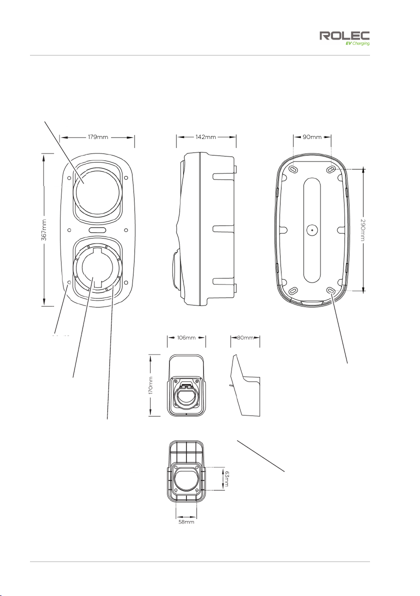
Product Overview
The WallPod is an affordable and reliable EV charging unit, which is ideal for both
domestic and commercial locations, providing up to 7.4kW fast charging.
This future-proof, OCPP compliant unit can offer a simple plug & charge or a pay-to
charge solution via the EV driver’s smartphone and/or RFID card/fob through any chosen
OCPP back-office management system.
Feature-rich, this EV charger supports dynamic load balancing and is equipped with PME
fault detection, so there is no requirement for an earth rod, reducing installation costs.
Domestic users can also charge their vehicle as sustainably as possible using their solar PV
or other home renewable for a zero-cost, zero-carbon charge. *
*App dependent feature:
Model Number Specification
ROLEC4020G WallPod Intelligent EV Charging Unit - up to 7.4kW Type 2 Socket - Grey
ROLEC4020W WallPod Intelligent EV Charging Unit - up to 7.4kW Type 2 Socket - White
ROLEC4020B WallPod Intelligent EV Charging Unit - up to 7.4kW Type 2 Socket - Black
ROLEC4140G WallPod Intelligent EV Charging Unit - up to 7.4kW Type 2 5m Tethered - Grey
ROLEC4140W WallPod Intelligent EV Charging Unit - up to 7.4kW Type 2 5m Tethered - White
ROLEC4140B WallPod Intelligent EV Charging Unit - up to 7.4kW Type 2 5m Tethered - Black
ROLEC4145G WallPod Intelligent EV Charging Unit - up to 7.4kW Type 2 10m Tethered - Grey
ROLEC4145W WallPod Intelligent EV Charging Unit - up to 7.4kW Type 2 10m Tethered - White
ROLEC4145B WallPod Intelligent EV Charging Unit - up to 7.4kW Type 2 10m Tethered - Black
NOTE: External tethered cable lengths are approximately 4.5m and 9.5m.
Product Features
xSuitable for both domestic and commercial
installations
xPlug & charge, mobile app or RFID controlled
charging
xUniversal charging socket or Type 2 tethered lead
xUp to 7.4kW charging output
xTruePEN PME fault detection (no earth rod
required)
xDynamic load balancing (CT clamp & cable
included)
xSolar PV, battery storage or wind turbine
integration *
xOCPP 1.6 compliant (Can integrate with any
compatible back-office)
xAlexa & Google assistant compatible *
xOver-the-air firmware / software updates
xBuilt-in overcurrent & 6mA DC leakage
protection
xCable lock security feature (can be
permanently locked by user)
xIntegrated RFID reader
xMID-approved energy metering
x4G / Wi-Fi / Ethernet connectivity
xIK10 impact resistant design
xWall or post mounted
xOZEV grant fundable
xDesigned & manufactured in the UK
*App dependent features:
NOTES:
xWhere mobile communications will be used, a signal strength of 14 CSQ or better is required at the
chargepoint.
xWhere Wi-Fi will be used the chargepoint must be in range of a wireless access point and the signal
must be strong and stable at the chargepoint. Users may need to consider an external antenna and/or
booster to their Wi-Fi system to reach remote chargepoints.
xFor Commercial installations, VendElectric is Rolec EV’s chargepoint management platform. Other
preferred partners are: Monta, Fuuse, and ChargePlace Scotland, but others include Parkable and
Ampeco.
xFor Domestic installations, our preferred partner is Monta who include 3 years free app connectivity
and support. Other preferred partners include ev.energy and Electric Miles.

Product Overview
WallPod Intelligent EV Charging Unit EVWM-V01-R1 Installation and Operation Manual
Page 5of 35 December 2022
NOTE: The United Kingdom has introduced new regulations (SI 2021/1467) that apply to
domestic and private EV chargepoints, and which aligns them with other ‘Smart’
appliances.
The new regulations are, amongst other things, designed to balance demands for
power and to deliver an efficient use of power across the country whilst maintaining a
consistent and secure service to EV drivers, when and where they need it.
The regulations are an ongoing, multi-part undertaking which may bring additional
requirements in the coming months and years.
About ‘Smart’ Services
Chargepoints are to be ‘Smart’ enabled.
‘Smart’ encompasses a large number of requirements but in summary these are:
xConnected to a ‘charging application’ such as VendElectric.
xThe ability to receive remote, online software updates.
xCapable of measuring the power used and the power delivered, and the associated
time periods.
xCapable of storing and displaying data about charge sessions to the owner and/or
user, via an application and/or on the chargepoint.
xCapable of communication with the power supplier and able to adjust the delivery of
power in response to commands issued by the supplier.
xCapable of charging even in the event of communications with the network being
lost. Data recorded about the charge session will be communicated at the next
available opportunity.
xThe ability to use other charging networks (that meet the Smart requirements).
xThe ability to receive power from any electricity supplier.
xIncorporates off-peak charging as the default with the ability to override if required.
xRandomised delay between initiating a charge session and the charge session
actually starting. This is to prevent overloads of the electricity system if a large number
of chargepoints are activated the moment the off-peak period starts.
xPhysical and digital protection of data and of the components used to access that
data.
xPhysical protection of electrical components within the chargepoint to prevent
personal harm and to prevent accidental or malicious tampering.

Product Overview
EVWM-V01-R1 Installation and Operation Manual WallPod Intelligent EV Charging Unit
December 2022 Page 6of 35
NOTE: When detailing Load Balancing and Load Management, this manual assumes the
installation of a single chargepoint. Whilst multiple chargepoints can be connected in a
similar way, installers may wish to consider connecting/monitoring using a third-party,
compliant energy management solution.
If connecting/monitoring via third-party equipment, make sure you are fully aware of
the manufacturer’s instructions so that the device/system can be installed correctly and
in conjunction with the chargepoint installation.
About Load Balancing
This chargepoint has a Load Balancing capability which is designed to prevent overloads
of the property’s power supply when a vehicle is being charged. This is similar in some
ways to Load Management but is NOT the same. Refer to the next page to read about
Load Management.
Once correctly installed and configured, the system will monitor the power being drawn
by the charging process and will compare this to the permissible maximum for the
property as a whole (which is set as part of the configuration). With this information, the
power made available for charging can be dynamically adjusted to reduce the load
before the property’s maximum load is exceeded.
For example, if the property’s main fuse (or circuit breaker) is rated at 60 Amps, the fuse
will operate and cut all power to the property if a draw of 60 Amps is exceeded.
It can be relatively easy to draw significant power if several property appliances are in use
at the same time.
Kettle 13 A
Oven 13 A
Dishwasher 10 A
Iron 13 A
Total = 49 A
In this example, only 11 Amps remain before the 60 Amp
limit is reached.
If an electric vehicle is now put on charge and is drawing
16 Amps, the limit would be exceeded, and the property’s
fuse would operate to cut all electrical power to the
property.
With load balancing enabled, the amount of power made available for charging will, if
required, be automatically adjusted to a level that does not exceed the maximum for the
property.
The system will continue to monitor the power and will dynamically increase and decrease
the power made available for charging in response to the demand for power from the
rest of the property.
Rolec chargepoints are pre-configured to load balance with a 13A ‘buffer’. This means
that whatever the property fuse may be, load balancing will start 13A before its maximum
limit is reached.
For example, if the charger is configured by the installer for use with a property with a 60A
fuse, load balancing will start at 47Amps. Similarly, for a property with an 80A fuse, load
balancing will start at 67Amps. This allows combined use of the charger plus other
appliances in normal use with no effect on the property’s electricity. You can then use up
to 13A more, with no risk of exceeding the maximum limit and load balancing will
continue to reduce charger power if more electricity is used by other appliances.

Product Overview
WallPod Intelligent EV Charging Unit EVWM-V01-R1 Installation and Operation Manual
Page 7of 35 December 2022
NOTE: Where a Rolec Load Balancing Current Transformer (CT) has been installed and
connected to a load balancing enabled Rolec chargepoint, it will reduce the supply of
power to the vehicle where the combined demand of the property and vehicle would
exceed the power available to the property as a whole.
xOnly 1 chargepoint is to be installed per phase to avoid counteracting behaviour.
xRolec cannot be held responsible for overloads of the supply caused by other
connected electrical items or failure of the vehicle to accept a reduced rate of
charge.
NOTES:
1. Load balancing ONLY controls power made available to the VEHICLE. It does not
control power to other equipment and it is still possible for that equipment to
overload the property’s power supply.
2. Depending on the manufacturer, electric vehicles need a minimum of around
6 Amps to charge. If the available power is below this level, the vehicle may stop
the charge session.
3. The lower the power available for charging, the more slowly the vehicle will be
charged.
About Load Management
This chargepoint is capable of Load Management. This is similar to load balancing in that
the power made available for charging can be dynamically adjusted to decrease or
increase the power available in response to other demands for power at the property.
The significant differences are that Load Management is:
xcontrolled by the software application used either within the chargepoint or via its
online connection (or a third-party device/system).
xmore often used where there are several chargepoints at the property, and where,
depending on pre-set criteria within the software, the system will control which
chargepoints receive the most power at any given point in time.
About Demand Side Response
Similar in some ways to Load Management, a Demand Side Response (DSR) system is
where the chargepoint and the electricity provider are in communication with each
other. The electricity provider will control the chargepoint remotely via the chargepoint
software to reduce the power it draws when it is needed by higher priorities in the area
and will increase power when those priorities reduce.
If the chargepoint is used with a DSR agreement in place, peak and off-peak charging will
not be implemented because the power company’s systems will control the charging
process.
Although the power drawn (and delivered) by the chargepoint can vary, this does not
necessarily protect the property power supply from being overloaded if the demand of
the property and vehicle exceed the power available to the property as a whole.

Product Overview
EVWM-V01-R1 Installation and Operation Manual WallPod Intelligent EV Charging Unit
December 2022 Page 8of 35
About PEN Protection
The TruePEN system removes the need to install a dedicated earth for the chargepoint.
In the event of a fault, the system will break all power cable connections between the
chargepoint and the vehicle.
A PEN fault is most commonly seen as either, an undervoltage or an overvoltage entering
the chargepoint from the mains supply. Following initial power ON, the TruePEN system
monitors the supply voltage for 5 seconds and determines if the voltage is within normal
operating parameters. If within limits, TruePEN allows the connection of Live, Neutral and
Earth to the vehicle and continues to monitor the supply.
If the voltage goes out of limits (below 207 Volts or above 253 Volts) for a continuous
period of 5 seconds, this could be caused by a PEN fault. The TruePEN device will activate
(‘trip’) and isolate Live, Neutral and Earth to the vehicle.
xUndervoltage – Following an undervoltage trip, TruePEN continues to monitor the
supply and if the voltage returns to within limits for a continuous period of 5
seconds, the TruePEN device will automatically reset and restore the Live, Neutral
and Earth connections to the vehicle, allowing charging to resume.
xOvervoltage – An overvoltage condition is potentially more likely to damage the
vehicle so, for safety reasons, automatic recovery following an overvoltage is NOT
provided and charging cannot resume until a manual reset is performed.
Following an overvoltage condition, EV drivers are advised to investigate as far as they
can, the reasons for the overvoltage condition and to check their vehicle for correct
operation.
Occasional overvoltage conditions may simply be caused by fluctuations in the supply
but if they are frequent, the cause should be investigated by an appropriately qualified
and experienced electrical engineer and/or the electricity supply company.
Security – Tamper Protection
In conjunction with a number of the ‘Smart’ requirements, it is a requirement in the United
Kingdom that chargepoints of this type, sold after 30 December 2022, have two-levels of
anti-tamper protection. If installed…
1. Chargepoints must incorporate a boundary to guard the electrical components
from tampering whilst also providing safety to engineers.
2. The chargepoint must log and issue an alert if there is a breach or an unsuccessful
attempted breach of the boundary.
The purpose of this protection is to:
xProtect people from harm.
xProtect the chargepoint, the charging network and the electricity network from
malicious or accidental damage or abuse.
xProtect the data held on the chargepoint and/or within the associated online
applications.

Product Specification
WallPod Intelligent EV Charging Unit EVWM-V01-R1 Installation and Operation Manual
Page 9of 35 December 2022
Product Specification
Figure 1 WallPod General Arrangement and Dimensions
Charging
Socket Cover
(Socket
ChargePoint
Only)
Enclosure
Fasteners
1 of 6
‘Halo’
LED
Status
Indicator
os
re
RFID
Reader
Location
Wall
Mounting
Point
1 of 4
Cable Tidy and
Plug Holster
(Tethered Cable
Chargepoints Only)

Product Specification
EVWM-V01-R1 Installation and Operation Manual WallPod Intelligent EV Charging Unit
December 2022 Page 10 of 35
Figure 2 WallPod Rear Enclosure Components
(For clarity, Wiring is not shown)
Figure 3 WallPod Front Enclosure Components
(For clarity, Wiring is not shown)
EV Charge
Controller
Meter Connector
CT Connectors
Status Indicator
‘Halo’ Connector
MID Meter
Incoming
Mains Power
Terminals
L, N, E.
Smart Link
Connection
Power ‘OUT’ and
Signal Connector
to Socket or
Cable
L, N, E.
Power ‘IN’
Connector to
PCB
N, E, L.
Rubber Seal
CANBUS
Connector
Connection to
Anti-Tamper Devices
SD Card Location
RJ45 LAN
Connector
Connection to RFID
Board
USB Connector
Smart
Communications
Module
t
Mobile Network
Antenna
Connection
RFID Reader
(Behind Coms PCB)
Status Indicator
‘Halo’
Connector
Socket Connector
(Socket Models Only)
Cable Lock
(Socket Models Only)
SIM Card
Location

Product Specification
WallPod Intelligent EV Charging Unit EVWM-V01-R1 Installation and Operation Manual
Page 11 of 35 December 2022
Figure 4 EV Charge Controller
Figure 5 Smart Communications Module
CANBUS
Connector
Connection to
Anti-Tamper Devices
SD Card Location
RJ45 LAN
Connector
Connection to RFID
Board
USB Connector
Fig
ure
5
Sma
rt
Com
Mobile Network
Antenna
Connection
SIM Card
Location
Meter Connector
2x CT
Connectors
Status Indicator
‘Halo’ Connector
Smart Link
Connection
C
C
C
C
Power ‘OUT’ and
Signal Connector
to Socket
L, N, E.
Power ‘IN’
Connector to
PCB
N, E, L.

Product Specification
EVWM-V01-R1 Installation and Operation Manual WallPod Intelligent EV Charging Unit
December 2022 Page 12 of 35
Connection
Type
Charging
Output
Input
Supply
Unit
Colour
Product
Code
Single
Phase
Units
1x Type 2 (IEC
62196)
charging socket
Up to 7.4kW (32A)
1x 32A
Single Phase
230V AC (±10 %)
50/60Hz
Grey ROLEC4020G
White ROLEC4020W
Black ROLEC4020B
1x Type 2 (IEC
62196)
5m tethered lead
Up to 7.4kW (32A)
1x 63A
Single Phase
230V AC (±10 %)
50/60Hz
Grey ROLEC4140G
White ROLEC4140W
Black ROLEC4140B
1x Type 2 (IEC
62196)
10m tethered
lead
Up to 7.4kW (32A)
1x 63A
Single Phase
230V AC (±10 %)
50/60Hz
Grey ROLEC4145G
White ROLEC4145W
Black ROLEC4145B

Product Specification
WallPod Intelligent EV Charging Unit EVWM-V01-R1 Installation and Operation Manual
Page 13 of 35 December 2022
User Interface
xMobile app
xRFID reader (Mifare ISO/IEC 14443 A)
xPlug & charge
xRGB LED status indicator halo – configurable
Charge Protocol Mode 3 (IEC 61851-1)
Protection
xAC overload & fault current protection – A dedicated 30mA Type A RCBO or equivalent
protection is required at source (see next page for options)
xOver current protection
xDC fault protection – 6mA
xLightning surge, over temperature protection
xTruePEN PME fault detection – No earth electrode/rod required
xSupports automatic dynamic load balancing (may require additional hardware)
xSupports static load management (software configurable)
Cable Terminals xSingle Phase – 3x 50mm 1P + N + E
Communications
x4G LTE Cat-1 (built-in nano SIM, subscription required)
xLTE FDD: B1/B3/B5/B7/B8/B20/B28
xGSM: B2/B3/B5/B8
xWi-Fi 802.11 b/g/n 2.4 GHz (2412-2472 MHz / 2422-2462 MHz)
xNFC 13.56 MHz
xRJ45 Ethernet connection
xBluetooth Low Energy (BLE 4.1) 2402-2480 MHz (for installer configuration purposes)
xOCPP 1.6J
xCyber security – Data encryption level TLS 1.2
Energy Metering Integrated Class 1 MID compliant metering
Standby Power
Consumption < 7.5W
Dimensions 179mm x 367mm x 142mm (W x H x D)
Weight < 2.8kg (model dependant)
Environmental
xIngress protection – Enclosure IP65, Socket IP54
xImpact protection – IK10
xSecurity – Dual tamper & breach notifications (optional in some units)
xOperating temperature – -30°C to +50°C
xOperating humidity – 5% to 95%
Materials xHigh impact resistant Polycarbonate
Unit Colour Black, Grey or White (Branding available upon request)
Certifications &
Compliances
xEV Charging Compliance – EN 61851-1:2019, EN 61851-22:2002
xSmart Charge Points – (SI 2021/1467) (Pre 2023 units may exclude Schedule 1)
xWiring Regulations – BS 7671:2018+A2:2022
xEMC Compliance – EN 61000-6-3:2007+A1:2011, EN 61000-6-2:2005, 2014/30 /EU, SI 2016/1091
xSafety Compliance (LVD) – EN 62368-1:2014, 2014/35/EU, SI 2016/1101
xCommunications / RED – EN 62311:2008, 2014/53/EU, SI 2017/1206,
EN 300 330 V2.1.1 (2017-02), EN 301 908-1 V15.1.1 (2021-09),
EN 301 908-13 V13.2.1 (2022-02), EN 301 511 V12.5.1 (2017-03),
EN 300 328 V2.2.2 (2019-07), EN 300 440 V2.2.1 (2018-07).
xEnvironmental Protection – BS EN 60529:1992+A2:2013
xImpact Rating – BS EN 62262:2002+A1:2021
xMetering – 2014/32/EU, SI 2016/1153
xRoHS – 2011/65/EU, SI 2012/3032
xREACH – 1907/2006, REACH etc. (Amendment) Regulations 2021
xCertification Markings – CE & UKCA
Warranty 3 years
Rolec Services Ltd are a registered manufacturer (WEE/AG3499TY) within the WEEE
Recycling Scheme, allowing its products at the end of their life, to be processed by an
appropriate local service provider.

Unpacking
EVWM-V01-R1 Installation and Operation Manual WallPod Intelligent EV Charging Unit
December 2022 Page 14 of 35
Unpacking
IMPORTANT: Make sure all packaging is disposed of responsibly and in accordance with
the current regulations in your region.
Packaging is 100% recyclable where appropriate facilities exist.
Standard Contents
xEV chargepoint
xConfiguration Tag
xVendElectric and Monta QR Code Socket ID Labels
xCurrent Transformer (CT) device with cable
xRemote cable hanger/plug holster (tethered units only)
xFixing Template – part of the packaging
xFixing Kit (Qty 4, 4 x 50mm screws and wall plugs)
xInstallation and Operation Manual
1. Examine the package and make sure the contents have not been damaged in
transit.
2. Make sure the chargepoint model and any accessories match the order.
3. Do NOT dispose of the packaging until the chargepoint has been installed and is
working correctly.
xPlease dispose of packaging responsibly when it is appropriate to do so.
NOTE: Items damaged in transit must first be reported to the courier and then to the
supplier. Where possible, photographic evidence of package and/or unit damage
should be supplied.
NOTE: Incorrect or damaged units must NOT be installed. Contact your supplier to
discuss rectification.
NOTE: If the supplied fixings are not suitable for the mounting location, the installer must
provide an appropriate alternative.
Options and Accessories
Product Code Item Description
RFID0010 RFID card
RFID0020 RFID fob
EVFP0020 Box section powder coated mounting post
EVCB0020 Root mount protection barrier – 48mm
EVCB0040 Surface mount protection barrier – 48mm
EVPS0010 EV parking sign – A4 landscape (Other sizes are available)
EVPP0100 5m 32A Type 2 to Type 2 charging cable
EVPP0107 10m 32A Type 2 to Type 2 charging cable (Other cables are available, including Type 1
options)
EVIN0010 20A Single Phase EV Consumer Unit with Type A RCBO
EVIN0015 40A Single Phase EV Consumer Unit with Type A RCBO
EVRS0030 Remote Wall Mount for Type 2 Charge Gun Holster
ACSR0125 100A, up to 35mm2screened CT clamp with 10m cable

Labelling
WallPod Intelligent EV Charging Unit EVWM-V01-R1 Installation and Operation Manual
Page 15 of 35 December 2022
Labelling
Observe any/all labels displayed on the equipment or inside the enclosure.
Figure 6 Typical Product Rating and
Serial Number Label
Figure 7 Configuration Tag (Back and Front)
Figure 8 Socket ID Label
Figure 9 RFID Label
Figure 10 Typical Socket Type and
power Rating Labels
NOTES:
1. Labels shown here are typical examples. Refer to the labels on the equipment.
2. Labels shown here are not to scale.
3. Additional labels may be located within the enclosure and used under instruction
of the configuration application.

Installation
EVWM-V01-R1 Installation and Operation Manual WallPod Intelligent EV Charging Unit
December 2022 Page 16 of 35
Installation
IMPORTANT: Installers and End Users must read and understand the content
of this manual before installation and/or use of the product.
Installation must only be performed by someone who is properly qualified and
competent to do so in accordance with the current legislation in force in the
geographical location of the installation.
xAdvice provided in this manual does NOT override any legislation.
xRolec Services Ltd cannot accept any responsibility for improper installation or any
problems arising from improper installation.
NOTE: Damage to the equipment, connected systems or to property caused by
improper installation are the responsibility of the installer.
BEFORE Installation
IMPORTANT: Signal Strength
Units that use mobile networks to communicate with a cloud-based back office contain
a roaming SIM card that connects to the strongest signal available.
It is assumed that a suitable mobile network signal has already been verified by the end
user/installer prior to installation.
xUnits using mobile networks require a suitable signal of 14 CSQ or better.
xUnits using Wi-Fi connectivity require a strong, stable connection.
xRolec cannot be held responsible or accountable in the event that a unit using a
mobile network or Wi-Fi is installed in a location without adequate network signal.
CAUTION: Equipment Damage – Sensitive Equipment
If you will be performing insulation resistance tests on the power supply cables, it is
advised to be done BEFORE connecting the power cable to the chargepoint. The high
voltages applied during the test may damage sensitive components if tested after the
cable is connected.
1. Establish a suitable site location for the unit that is both secure and environmentally
safe.
xMake sure the mounting location meets current legislation (if applicable).
xWhere a chargepoint with a tethered cable will be used, consider where the
chargepoint, and the cable and plug holster will be sited.
xWhere possible, choose a location that provides some shelter from extremes of
weather. Whilst the chargepoint (and associated equipment) meets or exceeds
the required standards, a sheltered location will provide additional protection
and make the chargepoint more pleasant to use.
xIf wall mounting will not be used, prepare the site by installing a mounting post.

Installation
WallPod Intelligent EV Charging Unit EVWM-V01-R1 Installation and Operation Manual
Page 17 of 35 December 2022
2. Make sure the electrical power available at the site is sufficient for the desired
power output from the chargepoint.
xChargepoint output power is managed by the chargepoint based on
information about the site entered into the Configuration Application after
installation.
xMaximum output per socket/plug is 230V/50hz, 7.4kW (32A).
3. Determine where power and other cables (CT and Ethernet – if required) will enter
the chargepoint enclosure.
xDiscuss cable routing and cable entry into the enclosure with the end user. Plan
the installation accordingly.
xDepending on the model of chargepoint, cables may enter through the
bottom or back of the rear half of the enclosure. Cable entry through the sides
or top of the chargepoint is NOT recommended.
4. If required, obtain fixings suitable to mount the WallPod in the chosen location.
xThe holes for wall mounting the enclosure are pre-made at 5 mm diameter.
5. Make sure that the WallPod and any options or accessories have not been
damaged in transit.
6. Make sure the unit model is correct and matches the order.
NOTE: Items damaged in transit must first be reported to the courier and then to the
supplier. Where possible, photographic evidence of package and/or item damage
should be provided.
NOTE: Incorrect or damaged units must NOT be installed. Contact your supplier to
discuss rectification.
7. Make sure a remote consumer unit has been installed (or appropriate switchgear is
available) in an appropriate location to supply power to the chargepoint. The
consumer unit must contain appropriately rated protective devices for the power
output that will be configured on the charger.
xFor total outputs of up to 32A, a 30mA Type A RCBO of appropriate rating must
be used.
8. Familiarise yourself with the schematic that is relevant to the product to be installed.
If a Mounting Post Will be Used
1. Prepare the ground and place the mounting post in the desired location.
xMake sure the power supply cable, the ethernet cable (if required), and the
Load Balancing CT cable (if required) are fed upward through the middle of
the post and exit through one of the apertures. Seal other apertures with the
provided blanking panels.
2. Secure the post into place with fixings that are appropriate for the mounting
surface.

Installation
EVWM-V01-R1 Installation and Operation Manual WallPod Intelligent EV Charging Unit
December 2022 Page 18 of 35
Schematics
Figure 11 WallPod Intelligent EV Charging Unit – 1x up to 7.4kW Type 2 Socket
NE
CP PP
L1
L2L3
kWh
1000
imp/kWh
230V 0.25-5(100)A
B
NN
2425 23 23 A
LIVE
NEUTRAL
EARTH
INCOMING SUPPLY
25 B
24 G
HALO LED STATUS
INDICATOR LEAD
HEADER
(FRONT VIEW)
2xWHITE
CABLES
HEADER
(FRONT VIEW)
LINK
B
A
WHITE
CABLE
(PP)
RED
CABLE
(CP)
L
N
E
PP CP
HIN GND
-HL +HL
LOAD BALANCING CT(TO BE CONNECTED TO A CT FITTED
AROUND THE HOME INCOMING SUPPLY LIVE WIRE)
OPTIONAL SOLAR MONITORING CT
H-
H+
S-
S+
MAGN ET 1
REED SWITCH 1
(TAMPER)
MAGNETIC
FIELD
REED SWITCH 2
(BREACH)
MAGN ET 2
MAGNETIC
FIELD

Installation
WallPod Intelligent EV Charging Unit EVWM-V01-R1 Installation and Operation Manual
Page 19 of 35 December 2022
Figure 12 WallPod Intelligent EV Charging Unit – 1x up to 7.4kW Type 2 Tethered Cable
kWh
1000
imp/kWh
230V 0.25-5(100)A
B
NN
2425 23 23 A
LIVE
NEUTRAL
EARTH
INCOMING SUPPLY
25 B
24 G
HALO LED
STATUS
INDICATOR
LEAD
HEADER
(FRONT VIEW)
2xWHITE
CABLES
HEADER
(FRONT VIEW)
LINK
B
A
L
N
E
PP CP
HIN GND
-HL +HL
LOAD BALANCING CT(TO BE CONNECTED TO A CT FITTED
AROUND THE HOME INCOMING SUPPLY LIVE WIRE)
OPTIONAL SOLAR MONITORING CT
H-
H+
S-
S+
MAGN ET 1
REED SWITCH 1
(TAMPER)
MAGNETIC
FIELD
REED SWITCH 2
(BREACH)
MAGN ET 2
MAGNETIC
FIELD
RED
CABLE
(CP)
RESISTOR
This manual suits for next models
21
Table of contents
Other ROLEC Batteries Charger manuals

ROLEC
ROLEC BasicCharge ROLEC0211B User manual

ROLEC
ROLEC ZURA ROLEC3020B User manual

ROLEC
ROLEC OCPP0410 User manual

ROLEC
ROLEC SecuriCharge ROLEC0111B User manual

ROLEC
ROLEC SECURICHARGE ROLEC0111 User manual

ROLEC
ROLEC EV SecuriCharge Series User manual

ROLEC
ROLEC EV Series User manual

ROLEC
ROLEC Sinexcel ULTRACHARGE 160 User manual

ROLEC
ROLEC Sinexcel ULTRACHARGE 160 User manual