Roller Grill 901 G Operation manual

Notice d’utilisation et d’insttddddqsdsq
Notice d’utilisation et d’installation (FR)
901 G / 902 G / 903 G
UTILISATION
Présentation de l’appareil
Les rôtissoires Gaz permettent de rôtir par rayonnement infrarouge (1050°C) volailles,
gibiers, gigots… Elles sont disponibles en 3 versions (capacité de 4, 8 ou 12 poulets) et sont
équipées d’un plat ramasse jus.
Ces appareils sont à usage professionnel et doivent donc être utilisés par du personnel
qualifié. Ils doivent être installés conformément aux réglementations en vigueur par un
installateur qualifié, et dans un local suffisamment aéré pour empêcher la formation de
concentration inadmissible de substances nocives pour la santé dans le local dans lequel il
est installé.
La plaque signalétique se situe à l’arrière de l’appareil.
Dimensions et capacité
Les modèles 901 G et 902 G sont équipés d’une zone d’étuvage.
Appareil Dimensions Poids Nombre
De broches Capacité
(nb de poulets)
901 G 800x350x665 30 Kg 1 4
902 G 800x350x870 40 Kg 2 8
903 G 800x350x870 40 Kg 3 12
Caractéristiques techniques
Appareil Débit
calorifique Nombre des
radiants
901 G 3.8 kW 1
902 G 7.6kW 2
903 G 11.4kW 3
Fonctionnement
Le moteur et le support broche sont montés sur glissière afin de positionner la broche plus
ou moins loin des radiants selon le type de cuisson désirée.
Les appareils sont équipés de 1, 2 ou 3 moteurs régulant chacun une broche.
Allumage Appuyer sur le bouton du robinet
Tourner le robinet sur la position grande flamme
Approcher une flamme près du brûleur
Maintenez le robinet appuyé pendant environ 5 secondes
Le brûleur reste alors allumé
Un thermocouple coupe l’alimentation en gaz en cas d’extinction d’un radiant.
Il est recommandé d’éteindre le brûleur lorsque la broche correspondante est vide de toute
pièce à cuire, afin d‘éviter un échauffement excessif de la vitre et de sa poignée.
Entretien
Votre appareil doit être régulièrement nettoyé à l’aide d’une éponge humide.
Ne nettoyer pas votre appareil sous un jet d’eau : les infiltrations risqueraient de
l’endommager.
Pour un meilleur service, nous vous conseillons un entretien tous les 6 mois à faire
effectuer par un installateur qualifié.
Votre appareil peut fonctionner avec différents types de gaz. Pour effectuer l’adaptation il
est nécessaire de faire appel à un installateur qualifié.
Installation
L’appareil doit être installé conformément aux réglementations en vigueur, dans un local
suffisamment aéré.
Les pièces scellées lors de la fabrication ne doivent pas être déprotégées par l’installateur
ou l’utilisateur.
Le débit d’air neuf requis pour l’alimentation en air de combustion est de :
901 G 7.6 m3/h
902 G 15.2m3/h
903 G 22.8m3/h
Note :Les parois latérales de votre appareil ne doivent pas être situées près d’un mur ou
d’une cloison constituée d’un matériau combustible ou si ce n’est pas le cas, le recouvrir
d’un matériau bon isolant thermique.
La distance de 30cm par rapport à une cloison est jugée suffisante.

Raccordement gaz
Les appareils fonctionnent aux gaz suivants : Butane G30, Propane G31, gaz naturel
G20/G25 et pour toutes les pressions rencontrées sur les réseaux de gaz. Le raccordement se
fait par un filetage G 1/2.
Les appareils sont livrés d’origine avec un injecteur Butane/Propane 100/100.
Raccorder l’appareil à la canalisation d’amenée de gaz en interposant une vanne de barrage
permettant d’isoler l’appareil du reste de l’installation. Vérifiez que les réglages
correspondent à la nature et à la pression du gaz du reste de l’installation.
Vérifiez la pression d’alimentation lorsque tous les brûleurs sont allumés, à l’aide d’un
manomètre. Celle-ci doit être égale aux indications de la plaque signalétique.
Conditions générales d’installation
L’installation et l’entretien de l’appareil doivent être effectués conformément aux textes
réglementaires et règles d’art en vigueur, notamment :
Règlement de sécurité contre l’incendie et la panique dans les établissements recevant du
public :
Prescriptions générales
1° Pour tous les appareils :
Article GZ Installations aux gaz combustibles et hydrocarbures liquéfiés
2° Ensuite, suivant l’usage :
Article CH Chauffage, ventilation, réfrigération, conditionnement d’air et
production de vapeur d’eau chaude sanitaire.
Article GC Installations d’appareils destinés à la restauration ;
Prescriptions particulières à chaque type d’établissements recevant du public
(Hôpitaux, magasins, etc…)
Changement de gaz (voir tableau ci-contre)
Important : Ne pas repercer les injecteurs.
Les injecteurs se démontent et remontent à l’aide d’une clé à œillet de 8.
Lors du passage de G30/G31 à G20/G25 il faut procéder au réglage du débit réduit. Pour se
faire, il faut dévisser la vis By Pass de 3 tours.
Dans le cas inverse visser la vis au maximum et retirer la bague d’air.
Pays de
Destination Catégorie Gaz Pressions ?Injecteur Bague d’air
France II2E+3+
II2E+3B/P
II2E+3P
G20/G25
G30/G31
G20/G25
G30
G31
G20/G25
G31
20/25
28-30/37
20/25
50
50
20/25
50
150
100
150
85
90
150
90
Sans
Sans
Sans
Sans
Sans
Sans
Sans
Allemagne II2ELL3B/P G20
G25
G30
G31
20
20
50
50
150
160
85
90
Sans
Sans
Sans
Sans
Autriche II2H3B/P G20
G30
G31
20
50
50
150
85
90
Sans
Sans
Sans
Belgique I2E+
I3+ G20/G25
G30/G31 20/25
28-30/37 150
100 Sans
Sans
Suède/Danemark/
Finlande II2H3B/P G20
G30/G31 20
28-30/30 150
100 Sans
Sans
Espagne II2H3+
II2H3P
G20
G30/G31
G20
G31
20
28-30/37
20
50
150
100
150
90
Sans
Sans
Sans
Sans
Luxembourg II2E3B/P
II2E3+
G20
G30
G31
G20
G30/G31
20
50
50
20
28-30/37
150
85
90
150
100
Sans
Sans
Sans
Sans
Sans
Pays-bas II2L3B/P
II2L3P
G25
G30/G31
G25
G31
25
28-30/30
25
50
150
100
150
90
Sans
Sans
Sans
Sans
Norvège I3B/P G30/G31 28-30/30 100 Sans
Islande/Grèce/Royaume
-Uni/Italie/Portugal II2H3+ G20
G30/G31 20
28-30/37 150
100 Sans
Sans
Raccordement électrique
Le moteur électrique doit être raccordé au réseau 220/230V monophasé.
Marquages
La plaque signalétique se situe au dos de l’appareil
En cas de changement de gaz, changez l’étiquette de réglage fournie avec la pochette.

Instruction for use and installation
901 G / 902 G / 903 G
USE
Description of the appliance
Gas rotisseries are designed for roasting poultry, game, joints, etc. using infrared radiation
(1050°C). They are available in 3 models (4, 8 and 12 chickens capacity) and are fitted with a
drip tray.
These appliances are for professional use and must therefore be used by qualified personnel.
They must be installed in accordance with current regulations by a qualified installer and in a
sufficiently well ventilated location.
The identification plate is located on the back of the appliance.
Dimensions and capacity
Models 901 G and 902 G are fitted with a warming area.
Appliance Dimensions Weight Number of
Spits Capacity
(no. Of chickens)
901G 800x350x665 30 Kg 1 4
902 G 800x350x870 40 Kg 2 8
903 G 800x350x870 40 Kg 3 12
Technical data
Appliance Heat
output Number of radiant
Burners
901 G 3.8 kW 1
902 G 7.6 kW 2
903 G 11.4 kW 3
Operation
The motor and the spit holder are fitted onto a sliding rack so that the distance of the spit
from the radiant burners can be varied according to the type of cooking required.
The appliances are fitted with 1, 2 or 3 motors which each drive a spit.
Lighting Press the knob and turn it on the big flame position
Place a flame close to the burner
Keep the knob pressed in for about 5 seconds
The burner will then remain lit
A thermocouple cuts off the gas supply if one of the radiant burners goes out.
It is recommended to turn off the burner when the spit support is empty, to avoid a high
temperature on the door.
Care and maintenance
Your appliance should be cleaned regularly using a damp sponge.
Do not clean your appliance under running water: water entering the system might damage
it.
For better and long lasting performance, regular checking carried out by qualified installer
are recommended.
Your appliance can operate on the various types of liquid petroleum gas. To change from
one gas to another requires the intervention of qualified installer.
Installation
The appliance must be installed in accordance with current regulations in a sufficiently
well ventilated location.
The fresh airflow required providing air for combustion is:
901 G 7.6m3/h
902 G 15.2m3/h
903 G 22.8m3/h
NB: The side panels of your appliance must not be placed next to a wall or partition
made from combustible material, otherwise, they must be covered in an effective heat
insulating material.
A distance of 30cm from the partition is deemed sufficient.

Gas connection
The appliances operate on the following gases: Butane G30, Propane G31, natural gases
G20/G25 and at all pressures encountered on main gas. Connection is with a G 1/2 thread.
The appliances are supplied from the factory with a Butane/Propane 100/100.
Connect the appliance to the gas supply pipe, interposing a stop valve, which enables the
appliance to be isolated from the rest of the installation. Check that the settings correspond to
the type and pressure of the gas distributed in the installation.
Check the supply pressure with all the burners alight using a gas manometer. This should be
the same as indicated on the identification plate.
General conditions for installation
The installation and the maintenance of the appliance must be carried out in accordance with
the current regulations and rulebook, in particular:
Regulations for the prevention of fire and panic in establishments when the public is
admitted.
General provisions:
1° For all appliances:
Article GZ Installations using combustible gases and liquid hydrocarbons
2° Next, depending on the use:
Article CH Heating, ventilation, refrigeration, air conditioning and the
production of steam from hot water in sanitary installations.
Article GC Installation of appliances to be used for catering. Specific
provisions for each type of establishment to which the public is admitted (hospitals, shops,
etc…).
Changing the gas
Important: Do not rebore the injectors.
The injectors are removed and replaced using a 8ring spanner.
To change the gas from G30/G31 to G20/G25 you must adjust the low position. For this,
unscrew the By Pass screw of 3 rounds. In the other case, screw the By Pass at the
maximum and take off the air collar.
Country of
Destination Category Gas Pressures ?Injector Air collar
France II2E+3+
II2E+3B/P
II2E+3P
G20/G25
G30/G31
G20/G25
G30
G31
G20/G25
G31
20/25
28-30/37
20/25
50
50
20/25
50
150
100
150
85
90
150
90
No
No
No
No
No
No
No
Germany II2ELL3B/P G20
G25
G30
G31
20
20
50
50
150
160
85
90
No
No
No
No
Austria II2H3B/P G20
G30
G31
20
50
50
150
85
90
No
No
No
Belgium I2E+
I3+ G20/G25
G30/G31 20/25
28-30/37 150
100 No
No
Sweden/Denmark/
Finland II2H3B/P G20
G30/G31 20
28-30/30 150
100 No
No
Spain II2H3+
II2H3P
G20
G30/G31
G20
G31
20
28-30/37
20
50
150
100
150
90
No
No
No
No
Luxembourg II2E3B/P
II2E3+
G20
G30
G31
G20
G30/G31
20
50
50
20
28-30/37
150
85
90
150
100
No
No
No
No
No
Netherlands II2L3B/P
II2L3P
G25
G30/G31
G25
G31
25
28-30/30
25
50
150
100
150
90
No
No
No
No
Norway I3B/P G30/G31 28-30/30 100 No
Iceland/Greece/United
kingdom/Italy/Portugal II2H3+ G20
G30/G31 20
28-30/37 150
100 No
No
Electrical connection
The electric motor must be connected to the single-phase 220/230 V mains supply
Maker’s name
The identification plate is located on the back of the appliance
If the gas is changed, change the setting label.

Manual de utilización y de instalación (ES)
901G / 902 G / 903 G
UTILIZACIÓN
Presentación del aparato
Los asadores a gas permiten asar por radiación infrarroja (1050ºC) aves, carnes de caza,
piernas, etc. Están disponibles en 3 versiones (capacidad de 4, 8 ó 12 pollos) y están
equipados de un plato para la recolección de jugos.
Estos aparatos son de uso profesional y por lo tanto se deben instalar conforme a las
reglamentaciones en vigor por un instalador cualificado, y en un local suficientemente
ventilado para impedir la formación de una concentración inadmisible de substancias nocivas
para la salud en el local en el cual está instalado.
La placa de señalización se sitúa en la parte trasera del aparato.
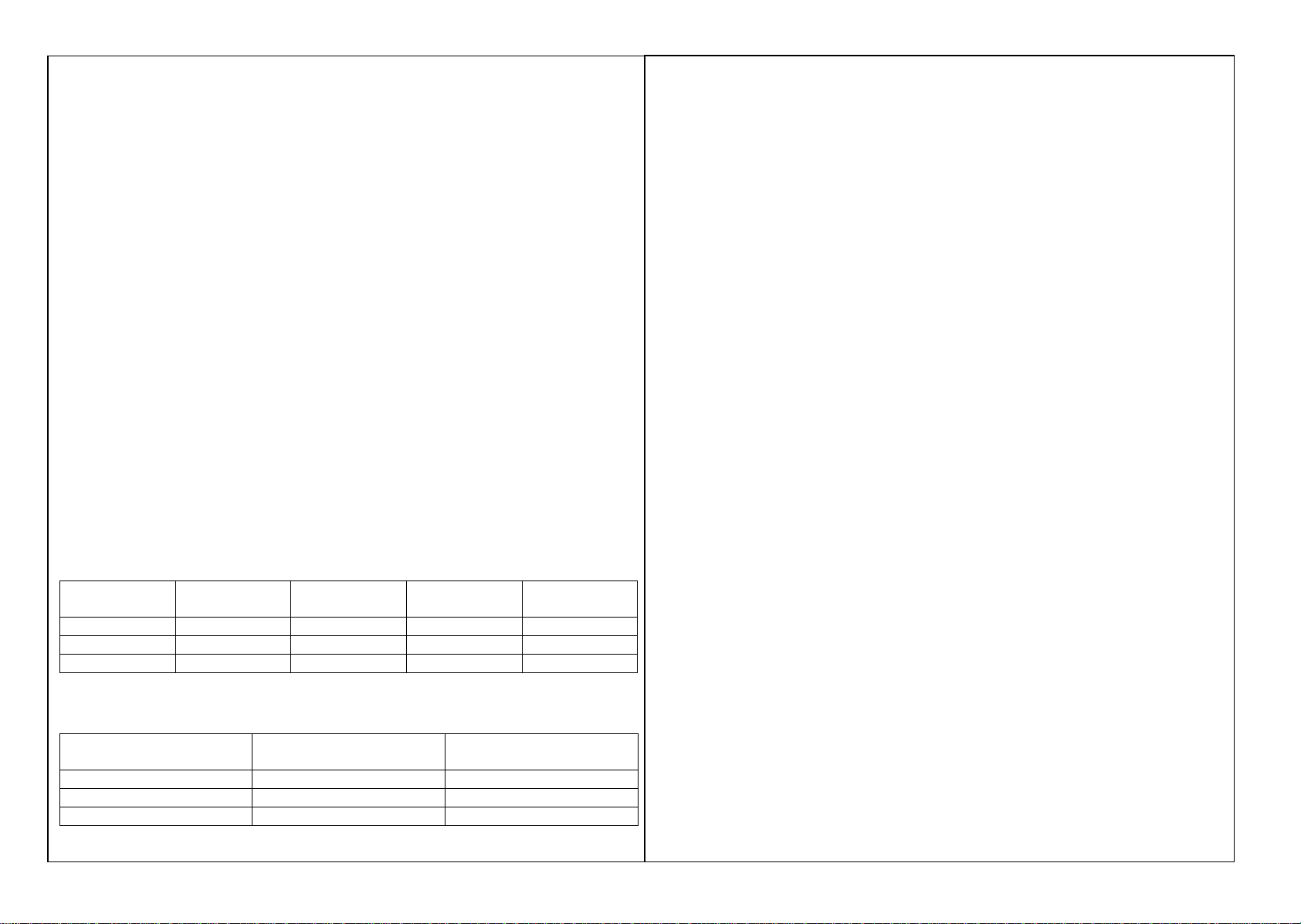
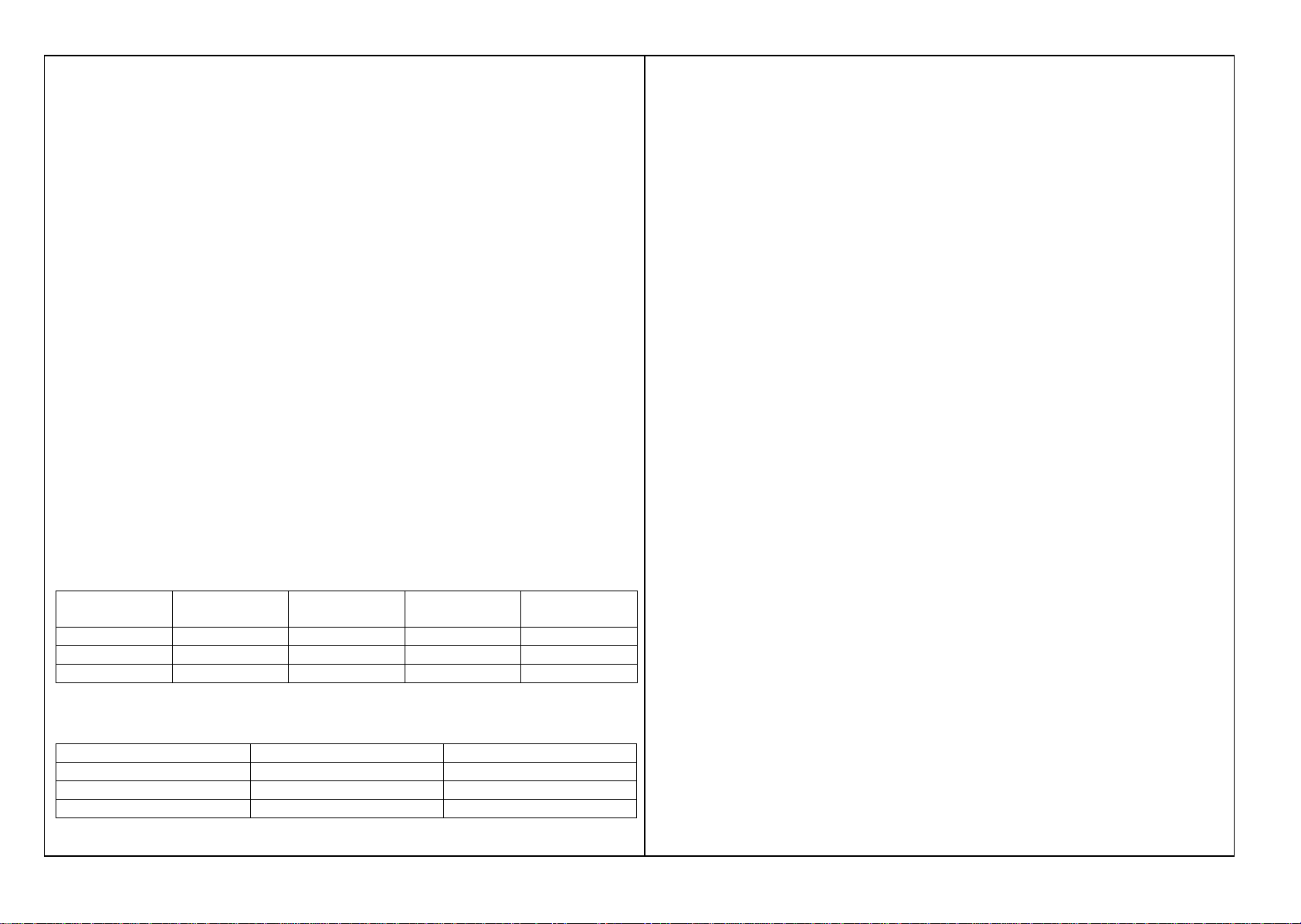
Dimensiones y capacidad
Los modelos 901 G, 902 G están equipados de una zona de estufa.
Aparato Dimensiones Peso Cantidad de
espetones Capacidad (cant.
De pollos)
901 G 800x350x665 30 Kg 1 4
902 G 800x350x870 40 Kg 2 8
903 G 800x350x870 40 Kg 3 12
Características técnicas
Aparato Caudal calorifico Cantidad de radiantes
901 G 3.8 kW 1
902 G 7.6 kW 2
903 G 11.4 kW 3
Funcionamiento
El motor y el soporte de espetón están montados sobre una corredera para posicionar el
espetón más o menos lejos de las radiaciones según el tipo de cocción deseada.
Los aparatos están equipados de 1, 2 o 3 motores que regulan cada uno un espetón.
Encendido: Pulsar el botón del grifo
Girar el grifo a la posición de llama grande
Acercar una llama cerca del quemador
Mantener el grifo pulsado aproximadamente 5 segundos
El quemador queda entonces encendido
Un termopar corta la alimentación de gas en caso de extinción de un radiante.
Se recomienda apagar el quemador cuando el espetón correspondiente está vacío de toda
pieza por cocer con el fin de evitar un calentamiento excesivo del vidrio y de su
empuñadura.
Mantenimiento
Su aparato se debe limpiar regularmente con la ayuda de una esponja húmeda.
No limpiar su aparato con un chorro de agua: las infiltraciones corren el riesgo de dañarlo.
Para un mejor servicio, le recomendamos un mantenimiento cada 6 meses que deberá
efectuar un instalador cualificado.
Su aparato puede funcionar con diferentes tipos de gas. Para efectuar la adaptación, es
necesario recurrir a un instalador cualificado.
Instalación
El aparato se debe instalar conforme a las reglamentaciones en vigor, en un local
suficientemente ventilado.
Las piezas selladas durante la fabricación no deben ser desprotegidas por el instalador o el
usuario.
El caudal de aire nuevo requerido para la alimentación de aire de combustión es de:
901 G 7.6m3/h
902 G 15.2m3/h
903 G 22.8m3/h
Nota: Las paredes laterales de su aparato no deben estar situadas cerca de una pared o de
un tabique constituido de un material combustible, o si no es el caso, recubrirlo con un
material que sea un buen aislante térmico.
Se considera como suficiente una distancia de 30 cm con respecto a un tabique.

Conexión de gas
Los aparatos funcionan con los siguientes gases: Butano, G30, Propano, G31, gas natural
G20/G25 y para todas las presiones encontradas en las redes de gas. La conexión se realiza
mediante una rosca G ½.
Los aparatos se suministran originalmente con un inyector Butano / Propano 100/100.
Conectar el aparato a la canalización de llegada de gas interponiendo una válvula de barrera
que permita aislar el aparato del resto de la instalación. Verifique que los ajustes
correspondan al tipo y a la presión del gas del resto de la instalación.
Verifique la presión de alimentación cuando todos los quemadores estén encendidos, con la
ayuda de un manómetro. Ésta debe ser igual a las indicaciones de la placa de señalización.
Condiciones generales de instalación
La instalación y el mantenimiento del aparato deben ser efectuados conforme a los textos
reglamentarios y reglas del arte en vigor, en particular:
Reglamento de seguridad contra incendios y el pánico en los establecimientos que reciben
público:
Prescripciones generales
1º Para los aparatos:
Artículo GZ Instalaciones de gas combustible e hidrocarburos licuados
2º Luego, según el uso:
Artículo CH Calefacción, ventilación, refrigeración, acondicionamiento de aire
y producción de vapor de agua caliente sanitaria.
Artículo GC Instalación de aparatos destinados a la restauración;
Prescripciones particulares a cada tipo de establecimiento que recibe público
(hospitales, tiendas, etc.).
Cambio de gas (ver el cuadro que figura al lado)
Importante: No volver a perforar los inyectores.
Los inyectores se desmontan y montan con la ayuda de una llave con ojal de 8.
Durante el paso de G30/G31 a G20/G25, se debe proceder al ajuste del caudal reducido.
Para ello, se debe desatornillar el tornillo de By Pass 3 vueltas. En el caso inverso, atornillar
el tornillo al máximo y retirar el anillo de aire.
País de destino Categoría Gas Presiones ?Inyector Anillo de aire
Francia II2E+3+
II2E+3B/P
II2E+3P
G20/G25
G30/G31
G20/G25
G30
G31
G20/G25
G31
20/25
28-30/37
20/25
50
50
20/25
50
150
100
150
85
90
150
90
Sin
Sin
Sin
Sin
Sin
Sin
Sin
Alemania II2ELL3B/P G20
G25
G30
G31
20
20
50
50
150
160
85
90
Sin
Sin
Sin
Sin
Austria II2H3B/P G20
G30
G31
20
50
50
150
85
90
Sin
Sin
Sin
Bélgica I2E+
I3+ G20/G25
G30/G31 20/25
28-30/37 150
100 Sin
Sin
Suecia / Dinamarca /
Finlandia II2H3B/P G20
G30/G31 20
28-30/30 150
100 Sin
Sin
España II2H3+
II2H3P
G20
G30/G31
G20
G31
20
28-30/37
20
50
150
100
150
90
Sin
Sin
Sin
Sin
Luxemburgo II2E3B/P
II2E3+
G20
G30
G31
G20
G30/G31
20
50
50
20
28-30/37
150
85
90
150
100
Sin
Sin
Sin
Sin
Sin
Países Bajos II2L3B/P
II2L3P
G25
G30/G31
G25
G31
25
28-30/30
25
50
150
100
150
90
Sin
Sin
Sin
Sin
Noruega I3B/P G30/G31 28-30/30 100 Sin
Irlanda / Grecia / Reino
Unido / Italia /Portugal II2H3+ G20
G30/G31 20
28-30/37 150
100 Sin
Sin
Conexión eléctrica
El motor eléctrico se debe conectar a la red de 220 / 230 V monofásica.
Marcaciones
La placa de señalización que se sitúa en el dorso del aparato.
En caso de cambio de gas, cambie la etiqueta de ajuste suministrada con la bolsa.

BEDIENUNGS-UND AUFSTELLUNGSHINWEISE
901 G / 902 G / 903 G
BEDIENUNG
Beschreibung des Gerätes
Die gasbeheizten Röstgeräte dienen zum Rösten von Geflügel, Wild, Lammkeulen usw.
durch Infrarotstrahlung (1050°C). Die Geräte sind in 3 Ausführungen
erhältlich (Fassungsvermögen für 4, 8 oder 12 Hähnchen) und besitzen eine Fettpfanne.
Die Geräte sind für den professionellen Gebrauch bestimmt und müssen daher von
qualifiziertem Personal bedient werden. Sie müssen entsprechend den gültigen Vorschriften
von einem Fachinstallateur in einem ausreichend belüfteten Raum installiert werden, so daß
sich in dem Raum keine unzulässige Konzentration gesundheitsschädlicher Stoffe bilden
kann.
Das Typenschild befindet sich auf der Geräterückseite.
Maße und Inhalt
Die Modelle 901 G, 902 G sind mit einem Dämpfbereich ausgestattet.
Gerät Maße Gewicht Anzahl Spieße Inhalt (Anzahl
Hähnchen)
901 G 800x350x665 30 Kg 1 4
902 G 800x350x870 40 Kg 2 8
903 G 800x350x870 40 Kg 3 12
Technische Daten
Gerät Wärmeleistung Anzahl Strahlkörper
901 G 3.8 kW 1
902 G 7.6 kW 2
903 G 11.4 kW 3
Funktionsweise
Motor und Spießträger sind auf einer Gleitschiene montiert, so daß sich der Spieß je nach
der gewünschten Bratstärke mehr oder weniger dicht am Strahlkörper einstellen läßt. Die
Geräte sind mit 1, 2 bzw. 3 Motoren versehen, die jeweils einen Spieß drehen.
Einschalten Auf den Knopf im Hahn drücken
Den Hahn auf große Flamme drehen
Eine Flamme an den Brenner halten
Den Hahn etwa 5 Sekunden gedrückt halten
Danach ist der Brenner gezündet
Falls ein Strahlkörper ausfällt, unterbricht ein Thermoelement die Gaszufuhr.
Wenn sich auf einem Spieß kein Bratgut befindet, wird empfohlen, den entsprechenden
Brenner abzuschalten, damit die Scheibe und ihr Griff nicht zu heiß werden.
Wartung
Ihr Gerät regelmäßig mit einem feuchten Schwamm sauberwischen. Es darf nicht unter
dem Wasserstrahl gereinigt werden, da eindringendes Wasser Schäden verursacht.
Für einen einwandfreien Betrieb empfehlen wir, das Gerät von einem Fachmann
halbjährlich warten zu lassen.
Ihr Gerät kann mit verschiedenen Gasen betrieben werden. Für die jeweilige Anpassung ist
ein Fachinstallateur hinzuzuziehen.
Installation
Das Gerät muß entsprechend den gültigen Vorschriften in einem ausreichend belüfteten
Raum aufgestellt werden.
Die Plomben der bei der Fertigung gesicherten Teile dürfen vom Installateur oder Benutzer
nicht gebrochen werden.
Zur Versorgung mit der nötigen Verbrennungsluft wird folgende Luftzufuhr benötigt :
901 G 7,6 m3/h
902 G 15,2 m3/h
903 G 22,8 m3/h
Hinweis : Die Seitenwände des Gerätes dürfen sich nicht in unmittelbarer Nähe einer
Mauer oder Wand aus brennbarem Material befinden, andernfalls müssen diese mit einem
guten Wärmedämmstoff geschützt werden.
Ein Abstand von 30 cm zur Wand gilt als ausreichend.

Gasanschlu€
Das Ger•t kann mit folgenden Gasen betrieben werden : Butan G30, Propan G31, Erdgas
G20/G25 mit allen in den Gasnetzen ‚blichen Druckwerten. Der Anschlu€ erfolgt ‚ber ein
Gewinde G 1/2.
Die Ger•te werden original mit einer Einla€d‚se f‚r Butan/Propan 100/100 geliefert.
Das Ger•t an die Gaszuf‚hrungsleitung anschlie€en ; dabei ein Absperrventil einf‚gen, um
das Ger•t von der ‚brigen Anlage trennen zu kƒnnen. Darauf achten, da€ die Einstellungen
mit Gasart und Gasdruck der ‚brigen Anlage ‚bereinstimmen. Mit einem Manometer den
Gasspeisedruck ‚berwachen, wenn alle Brenner eingeschaltet sind. Dieser Druck mu€ mit
den Angaben des Typenschildes ‚bereinstimmen.
Allgemeine Aufstellungsbedingungen
Aufstellung und Wartung des Ger•tes m‚ssen entsprechend den g‚ltigen Bestimmungen und
technischen Grundregeln ausgef‚hrt werden, insbesondere :
Sicherheitsvorschrift gegen Brand und Panik in R•umen mit „ffentlichkeitsbetrieb :
Allgemeine Vorschriften
1. F‚r alle Ger•te :
Artikel GZ Anlagen mit Brenngas und Fl‚ssigkohlenwasserstoffen
2. Anschlie€end je nach Verwendung :
Artikel CH Heizung, Bel‚ftung, K‚hlung, Klimatisierung und
Hei€wasserproduktion f‚r sanit•re Anlagen
Artikel GC Anlagen mit Ger•ten im Gastst•ttenwesen
Sondervorschriften f‚r jede Art von Einrichtung mit
„ffentlichkeitsbetrieb (Krankenh•user, Kaufh•user usw.)
…nderung der Gasversorgung (siehe nebenstehende Tabelle)
Wichtig :Die Gasd‚sen nicht nachbohren.
Die Gasd‚sen lassen sich mit einem Ringschl‚ssel Nr. 8aus-bzw. einbauen.
Bei der Umstellung von G30/G31 auf G20/G25 mu€ die verringerte gas druck eingestellt
werden. Dazu die By-Pass-Schraube um 3 Umdrehungen lƒsen. Im umgekehrten Fall die
Schraube ganz einschrauben und den Luftring entfernen.
Bestimmungsland Klasse Gas Druck † Gasd‚se Luftring
Frankreich II2E+3+
II2E+3B/P
II2E+3P
G20/G25
G30/G31
G20/G25
G30
G31
G20/G25
G31
20/25
28-30/37
20/25
50
50
20/25
50
150
100
150
85
90
150
90
Ohne
Ohne
Ohne
Ohne
Ohne
Ohne
Ohne
Deutschland II2ELL3B/P G20
G25
G30
G31
20
20
50
50
150
160
85
90
Ohne
Ohne
Ohne
Ohne
„sterreich II2H3B/P G20
G30
G31
20
50
50
150
85
90
Ohne
Ohne
Ohne
Belgien I2E+
I3+
G20/G25
G30/G31
20/25
28-30/37
150
100
Ohne
Ohne
Schweden/D•nemark/
Finnland
II2H3B/P G20
G30/G31
20
28-30/30
150
100
Ohne
Ohne
Spanien II2H3+
II2H3P
G20
G30/G31
G20
G31
20
28-30/37
20
50
150
100
150
90
Ohne
Ohne
Ohne
Ohne
Luxemburg II2E3B/P
II2E3+
G20
G30
G31
G20
G30/G31
20
50
50
20
28-30/37
150
85
90
150
100
Ohne
Ohne
Ohne
Ohne
Ohne
Niederlande II2L3B/P
II2L3P
G25
G30/G31
G25
G31
25
28-30/30
25
50
150
100
150
90
Ohne
Ohne
Ohne
Ohne
Norwegen I3B/P G30/G31 28-30/30 100 Ohne
Island/Griechenland/Gr
o€britannien/Italien/Por
tugal
II2H3+ G20
G30/G31
20
28-30/37
150
100
Ohne
Ohne
Elektrischer Anschlu€
Der Elektromotor wird an ein Einphasenstromnetz 220/230V angeschlossen.
Markierungen
Das Typenschild befindet sich auf der Ger•ter‚ckseite.
Bei Benutzung eines anderen Gases das im Beutel mitgelieferte Etikett auswechseln.

This manual suits for next models
2
Table of contents
Languages:
Other Roller Grill Kitchen Appliance manuals

Roller Grill
Roller Grill PZ 430 S Operation manual

Roller Grill
Roller Grill CVE 400 Operation manual

Roller Grill
Roller Grill CFG 400 Operation manual

Roller Grill
Roller Grill CFE 400 Operation manual

Roller Grill
Roller Grill CSE 350 Operation manual

Roller Grill
Roller Grill PZ 430 D Operation manual

Roller Grill
Roller Grill RBE 80 Operation manual

Roller Grill
Roller Grill CSG 400 Operation manual

Roller Grill
Roller Grill RBG 80 Operation manual

Roller Grill
Roller Grill RBE80Q Operation manual