Ropox 40-44010 User manual

Ropox Support Washbasin
Fixed –Basic - Manual
USER MANUAL
MOUNTING INSTRUCTIONS
Keep this manual with the product at all times
TF 200.01.0047_eng / Dato 29-08-2022
PA 2004 00634

2
TF 200.01.0047_eng
Table of Contents
1. SYMBOLS USED IN THIS MANUAL................................................................................................. 3
2. GENERAL SAFETY .......................................................................................................................... 3
2.1PRODUCT UNIT LABEL ........................................................................................................................... 5
3. GENERAL REQUIREMENTS............................................................................................................ 6
3.1PRODUCT INFORMATION ........................................................................................................................ 6
3.2PRODUCT DESCRIPTION......................................................................................................................... 6
3.3INTENDED USE...................................................................................................................................... 6
3.4INTENDED OPERATOR ............................................................................................................................ 7
3.5ESSENTIAL PERFORMANCE..................................................................................................................... 7
3.6NONCLINICAL FUNCTIONS....................................................................................................................... 7
3.7CLINICAL FUNCTIONS............................................................................................................................. 7
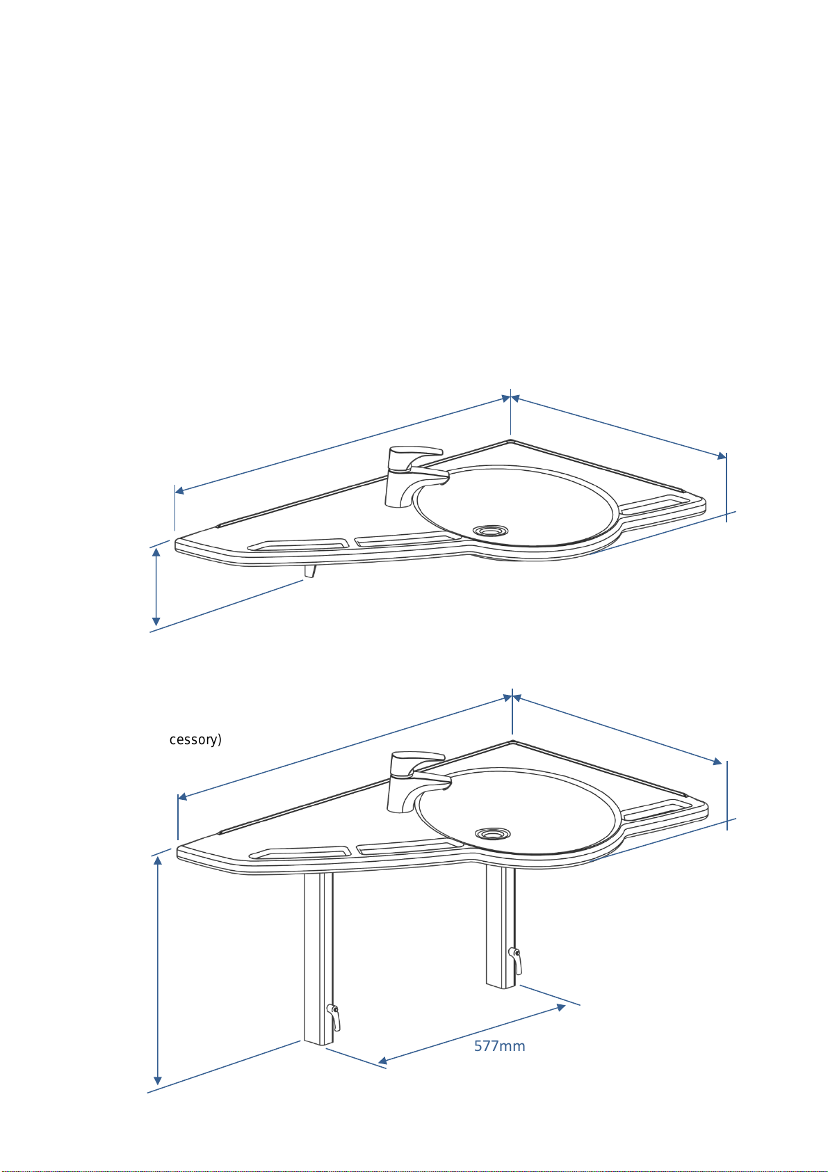
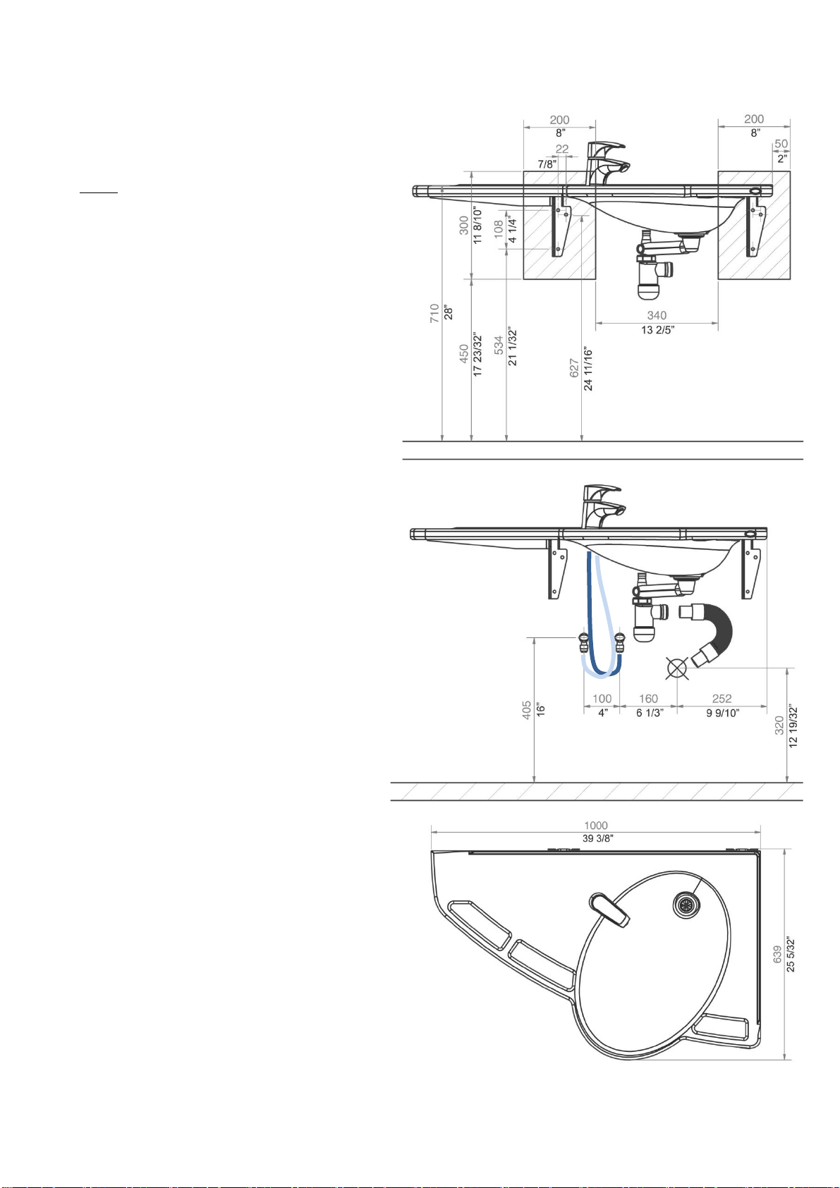
3.8PRODUCT DIMENSIONS .......................................................................................................................... 7
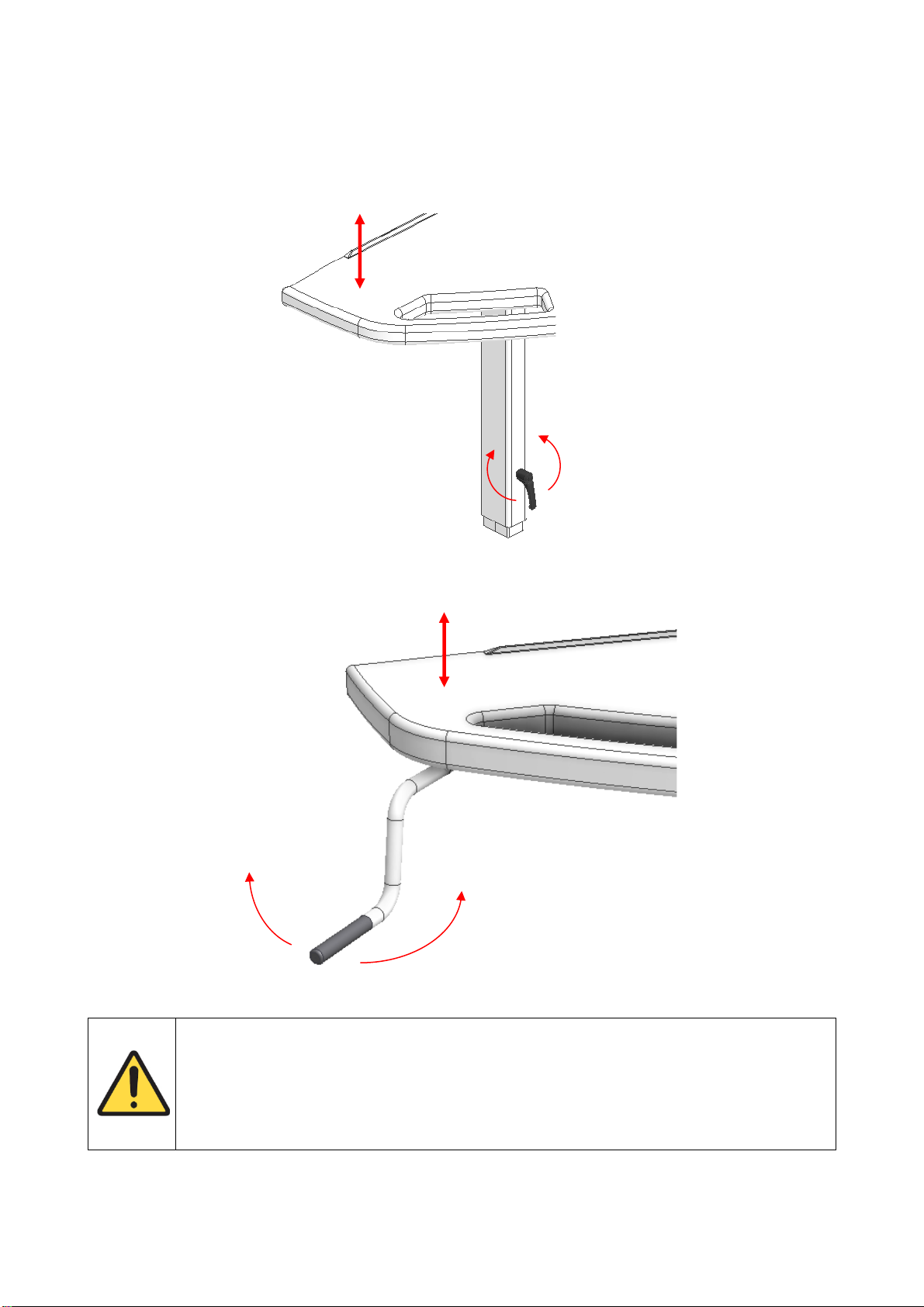
3.9OPERATION.......................................................................................................................................... 9
4. MOUNTING INSTRUCTIONS...........................................................................................................10
4.1INSTALLATION INTERFACES ...................................................................................................................10
4.2CONNECTION ADAPTERS.......................................................................................................................13
4.3LIST OF COMPONENTS ..........................................................................................................................14
4.4INSTALLATION OF PRODUCT...................................................................................................................16
4.4.1 Support Washbasin, Fixed (40-44010/11).................................................................................16
4.4.2 Support Washbasin with Basic frame (40-4012/13)...................................................................17
4.4.3 Mounting of covers for 40-44012/13 (accessories)....................................................................22
4.4.4 Support Washbasin with Manual frame (40-44014/15)..............................................................26
4.4.5 Mounting of covers for 40-44014/15..........................................................................................34
5. PERFORMANCE TEST....................................................................................................................38
6. SAFETY IN USE...............................................................................................................................38
7. SERVICE AND MAINTENANCE.......................................................................................................39
7.1CLEANING ...........................................................................................................................................39
7.2CLEANING OF WASHBASIN .....................................................................................................................39
7.3INSPECTION.........................................................................................................................................39
7.4SERVICE SCHEDULE .............................................................................................................................40
8. FAULT FINDING ..............................................................................................................................40
9. LIST OF SPARE PARTS..................................................................................................................41
10. ENVIRONMENTAL PROTECTION...................................................................................................41
11. COMPLAINTS..................................................................................................................................41

3
TF 200.01.0047_eng
1. Symbols used in this manual
Warning Symbol
Indication of potentially hazardous situation. If not avoided, it can result in serious injury or
death.
Caution Symbol
Indication of potentially hazardous situation which may result in minor or moderate injury.
It may also be used to alert against unsafe practices.
Notification Symbol
This symbol is used to notify correct use and handling of the product.
2. General safety
This manual must be read and understood before use.
Always keep this manual in close proximity of the product.
The use, installation and service of this product must be in
compliance with this manual to avoid accidents and serious
personal injury.
Never use or handle this product in other ways specified in
this manual as it can result in personal safety hazards and/or
cause damage to the product.
Persons installing and/or using this product either as operator
or user should have the necessary safety information and
access to this manual.
If the supply cord is damaged, it must be replaced by the
manufacturer, its service agent or similarly qualified
designated persons in order to avoid a hazard.

4
TF 200.01.0047_eng
Do not perform repairs, disassembly or assembly operations,
add-ons, re-adjustments or modification of the product
beyond what is described in this manual. These must be
carried out by Ropox or Ropox authorized personnel. Do not
perform service while in use.
This appliance can be used by children aged from 8 years
and above and persons with reduced physical, sensory or
mental capabilities or lack of experience and knowledge if
they have been given supervision or instruction concerning
use of the appliance in a safe way and understand the
hazards involved. Children shall not play with the appliance.
Cleaning and user maintenance shall not be made by
children without supervision.
Do not use the product if it has defects or have become
damaged before being repaired or replaced.
If the control box makes unusual noise or smells, switch off
the mains voltage immediately.
Take care that the cables are not damaged.
Unplug the mains cable on mobile equipment before it is
moved.
The products must only be used in an environment that
corresponds to their IP protection.
The information in this manual is based on correct installation
in accordance with installation instructions for this product.
Ropox cannot be held liable if the product is used in any way
that differs from stated in this manual and/or installation
instruction.
Ropox reserve the right to amend this manual and reference
documents without prior notice.

5
TF 200.01.0047_eng
2.1 Product Unit label
This product is UKCA-marked in accordance with:
UK SI 2002 No. 618 - The Medical Devices Regulations 2002, and its amendments
UK SI 2008 No. 1597 - The Supply of Machinery (Safety) Regulations 2008, and its
amendments
This product is CE-marked in accordance with:
European Medical Device Regulation (EU)2017/745
Council Directive 2006/42/EC on machinery
Council Directive 2011/65/EU, RoHS
Manufacturer name and address
Date of production
Stock number
Serial number
Consult manual for important safety related information, warnings and safety
precautions.
Do not dispose as unsorted municipal waste. Product must be returned to a
designated recycling station.
Operating and storing temperatures may not exceed 5-40C°
Consult the instructions for use
Ropox Support washbasin, Manual, L
Mixer tap left side. Integrated handles

6
TF 200.01.0047_eng
3. General requirements
3.1 Product information
Manufacturer
Ropox A/S
Ringstedgade 221, DK-4700 Naestved
+45 55 75 05 00
Info@ropox.com
Product models
Part number
Model
Configuration
40-44010
40-44011
40-44012
40-44013
40-44014
40-44015
Support Washbasin
Support Washbasin
Support Washbasin
Support Washbasin
Support Washbasin
Support Washbasin
Fixed L
Fixed R
Basic L
Basic R
Manual L
Manual R
Expected service life
5 years
MDR Class
2017/745
Class I
Intended environments
This product is to be used only in:
Professional Healthcare Environment
Homecare Environment
Height adjustment
Basic = 71-101cm
Manuel = 71-101cm
Maximum user weight
according to ISO
17966:2016
400 kg / 881 lb
Ambient temperature
range
-10 °C to +50 °C Transport and storage
+5 °C to +40 °C Operation
Realtive humidity
20% to 80% - non-condensing
Materials in contact
with patient
Wash basin
Frame
Mixer tap
Synthetic/marble composite
Welded steel pipes St. 37, aluminum
Chrome
Accessories
40-40935
40-44021
40-44022
40-44027
40-44028
40-44020
40-44033
40-44040
Plug with overflow
Cover plates left, for Fixed and Basic
Cover plates right, for Fixed and Basic
Cover plates left, for Manual
Cover plates right, for Manual
Plumbing kit for Manual
Plumbing kit for Fixed and Basic
Mixer tap
3.2 Product description
The Ropox Support Washbasin is a disability-friendly and stable washbasin, which is adjustable in height,
based on the needs of the individual. The washbasin is specifically designed for use by people with difficulty
walking. It has integrated grab rails, to prevent fall injury.
3.3 Intended use
The support washbasin is especially suitable for walking-impaired because you can use the integrated,
ergonomic grab rails as support and as help when getting up or sitting down. The washbasin is available with
fixed height and with height adjustment. It is possible to choose between manual or electrical height
adjustment. This makes it able to suit the individual user who will be using the washbasin.

7
TF 200.01.0047_eng
3.4 Intended operator
Reading and understanding this manual will be sufficient training for an intended operator. Children under
the age of 16 or patient are not considered intended operator.
3.5 Essential performance
The product does not have essential performance, as the patient and user do not experience any risk in case
of loss of product function/performance.
3.6 Nonclinical functions
Height adjusting offers better ergonomics to the user.
3.7 Clinical functions
The product does not have any clinical functions.
3.8 Product dimensions
Fixed
40-44001/11
(Mixertap is accessory)
Basic height adjustment
40-44012/13
(Mixertap is accessory)
1000mm
633mm
166mm
1000mm
633mm
518mm
577mm

8
TF 200.01.0047_eng
Manual height adjustment
40-44004/05
(Mixertap is accessory)
Accessories –covers
40-44021/22
633mm
1000mm
580mm
657mm
125mm
273mm
90mm
550-850mm
653mm

9
TF 200.01.0047_eng
3.9 Operation
Basic height adjustment (applying to 40-44012/13)
The height of the washbasin may be adjusted by loosening the two handles.Note that the washbasin must
be supported while loosening the handles in order to prevent it from falling to the bottom position. Covers, if
any, must be removed before adjustment of these models.
Manual height adjustment (applying to 40-44014/15)
The height of the washbasin may be easily adjusted by means of the detachable hand crank.
Warning!
The product should always be able to travel the full range of actuation without colliding with
objects. Failing to do so will compromise the product stability and introduce risk of squeezing
body parts.
Special care should be taken in ensuring that no children or adults are sited under the
product as severe injury from entrapment may occur.

10
TF 200.01.0047_eng
4. Mounting instructions
4.1 Installation interfaces
Fixed
(40-44010 and 40-44011)
Construction
The wall must be made of a material suited for
screw mounting and approved for damp rooms.
The hatched area is the minimum area for
reinforcement of the wall. Reinforcement from
floor to ceiling is advisable.
Load-tested in Accordance with DS/ISO 17966,
the maximum user weight has been fixed at
400kg (881 lbs).
Max. tensile load of upper screws
150kg/screw (330 lbs)
The washbasin is supplied with a set of 6 screws
and rawlplugs suitable for mounting on a
concrete wall. The fitter should always consider
the material, condition and strength of the wall
and use screws and rawlplugs suitable for the
specific wall type.
Plumbing
The drain is Ø32 (1 ¼”) and ends in an
Ø32x88.5° drain elbow.
The maximum protrusion of drain connection
and elbow from the wall is 90mm (3 ½”) to
allow for the covers.
The water supply ends in 2 (two) 90° shut-off
valves with ½” outside thread pointing
downward (not included).
The maximum protrusion of the shut-off valves
from the wall is 90mm (3 ½”) to allow for the
covers.
If a location of the water supply and drain
different from the recommended positioning is
required or if there is a floor drain, the Support
Washbasin will have no covers.
For purchase of adapters for connection to
various standard installations, see ”Connection
Adapters –Other Washbasins”.
Note
All dimensions are based on a washbasin height of
710mm (28”) above floor level. If a change of this
height is required, the recommended dimensions
must be changed accordingly.
The illustrations show the left-hand model 40-
44010

11
TF 200.01.0047_eng
Basic
(40-44012 and 40-44013)
Construction
The wall must be made of a material suited
for screw mounting and approved for damp
rooms.
The hatched area is the minimum area for
reinforcement of the wall.
Reinforcement from floor to ceiling is
advisable.
Load-tested in Accordance to DS/ISO 17966,
the maximum user weight has been fixed at
400kg (881 lbs).
Max. tensile load of upper screws
85kg/screw (187 lbs)
The washbasin is supplied with a set of 6
screws and rawlplugs suitable for mounting
on a concrete wall. The fitter should always
consider the material, condition and strength
of the wall and use screws and rawlplugs
suitable for the specific wall type.
Plumbing
The drain is Ø32 (1 ¼”) and ends in an
Ø32x88.5° drain elbow.
The maximum protrusion of drain connection
and elbow from the wall is 90mm (3 ½”) to
allow for the covers.
The water supply ends in 2 (two) 90° shut-off
valves with ½” outside thread pointing
downward (not included).
The maximum protrusion of the shut-off valves
from the wall is 90mm (3 ½”) to allow for the
covers.
It is important that all hoses for water
connection and drain are flexible to allow the
frame to move freely within the height
adjustment range of 710-1010mm (28” – 39
8/10”) (including washbasin).
If a location of water supply and drain different
from the recommended positioning is required
or if there is a floor drain, the Support Washbasin
will have no covers.
For purchase of adapters for connection to
various standard installations, see ”Connection
Adapters –Other Washbasins”.
Note
The illustrations show the left-hand model 40-
44012

12
TF 200.01.0047_eng
Manual
(40-44014 and 40-44015)
Construction
The wall must be made of a material suited
for screw mounting and approved for damp
rooms.
The hatched area is the minimum area for
reinforcement of the wall.
Reinforcement from floor to ceiling is
advisable.
Load-tested in Accordance with DS/ISO
17966, the maximum user weight has been
fixed at 400kg (881 lbs).
Max tensile load of upper screws
71kg/screw (157 lbs)
The washbasin is supplied with a set of 8
screws and rawlplugs suitable for mounting
on a concrete wall. The fitter should always
consider the material, condition and
strength of the wall and use screws and
rawlplugs suitable for the specific wall type.
Plumbing
The drain is Ø32 (1 ¼”) and ends in an
Ø32x88.5° drain elbow.
The maximum protrusion of drain connection of
elbow from the wall is 90mm (3 ½”) to allow for
the covers.
The water supply ends in 2 (two) 90° shut-off
valves pointing downward (not included). The
maximum protrusion of the shut-off valves from
the wall is 90mm (3 ½”) to allow for the covers
It is important that all hoses for water
connection and drain are flexible to allow the
frame to move freely within the height
adjustment range of 710-1010mm (28” – 39
8/10”) (including washbasin).
If a location of water supply and drain different
from the recommended positioning is required
and if there is a floor drain, the Support
Washbasin will have no covers.
For purchase of adapters for connection to
various standard installations, see ”Connection
Adapters –Other Washbasins”.
NOTE: The illustrations show the left-hand
model 40-44014

13
TF 200.01.0047_eng
4.2 Connection adapters
The highlighted components can be bought separately depending on the type of building installation
requirements.
Water supply
Hoses from basin
Adapters
Installation in room
(not included)
No adapter
necessary
1/2"
Thread
1/2" -> 3/8"
Item no. 97001670
3/8"
Thread
1/2" -> 15mm
Item no. 97001666
15mm
Pipe
Water hose extensions
Hose from basin
Coupling piece
Extra hose
1/2" -> 1/2"
Item no. 97001662
1/2" x 1/2", 0,5m, steel
Item no. 97001123
1/2" x 1/2", 1m, plastic
Item no. 97001120
Drain
Drain pipe from basin
Adapters
Installation in room
(not included)
No adapter
necessary
Ø32
Ø32 -> Ø40
Item no. 97001660
Ø40
Ø32 -> Ø50
Item no. 97001661
Ø50
Drainpipe extensions
Drainpipe from basin
Coupling piece
Extra drainpipe
Ø32-Ø32
Item no. 97001662
Ø32 Flex hose, 27-62cm
Item no. 97001162
Ø32 Flex hose, 40-110cm
Item no. 97001161
1/2”
Ø32
Ø32

14
TF 200.01.0047_eng
4.3 List of components
Ropox Support Washbasin, Fixed, left, 40-44010
40*44010-064: Top plate with washbasin, left-oriented 1 (one)
Provided with:
40*44010-063: Fixed wall bracket, long 1 (one)
40*44010-062: Fixed wall bracket, short 1 (one)
40*44010-048: Frame Basic side bracket 1 (one)
Ropox Support Washbasin, Fixed, right, 40-44011
40*44010-070: Top plate with washbasin, right-oriented 1 (one)
Provided with:
40*44010-063: Fixed wall bracket, long 1 (one)
40*44010-062: Fixed wall bracket, short 1 (one)
40*44010-048: Frame Basic side bracket 1 (one)
Ropox Support Washbasin, Basic height adjustment, left, 40-44012
40*44010-064: Top plate with washbasin, left-oriented 1 (one)
Basic height-adjustment brackets 1 (one) set
Incl.
40*44010-025 Long bracket
40*44010-026 Short bracket
40*44010-020 Inside legs
97800-022 Threaded plate
97001631 Adjustable handles
40*44010-048 Frame Basic side bracket
Ropox Support Washbasin, Basic height adjustment, right, 40-44013
40*44010-070: Top plate with washbasin, right-oriented 1 (one)
Basic height-adjustment brackets 1 (one)
Incl.
40*44010-025 Long bracket
40*44010-026 Short bracket
40*44010-020 Inside legs
97800-022 Threaded plate
97001631 Adjustable handles
40*44010-048 Frame Basic side bracket

15
TF 200.01.0047_eng
Ropox Support Washbasin, Manual height adjustment, left, 40-44014
40*44010-064: Top plate with washbasin, left oriented 1 (one)
Provided with:
Top frame, left oriented 1 (one)
Incl.
40*44010-042 Frame Manual support, left
40*44010-057 Hand crank assembly left
30-67600: Flexi legs, Manual 2 (two) sets
Incl. Cover
Distance blocks
40*44010-038: Hexagonal shaft 1 (one)
20*60320-548: Hand crank 1 (one)
Ropox Support Washbasin, Manual height adjustment, right, 40-44015
40*44010-070: Top plate with washbasin, right-oriented 1 (one)
Provided with: Top frame, right-oriented 1 (one)
Incl.
40*44010-077 Frame Manual support, right
40*44010-082 Hand crank assembly, right
30-67600: Flexi legs, Manual 2 (two) sets
Incl. Cover
Distance blocks
40*44010-038: Hexagonal shaft 1 (one)
20*60320-548: Hand crank 1 (one)

16
TF 200.01.0047_eng
4.4 Installation of product
4.4.1 Support Washbasin, Fixed (40-44010/11)
Recommended:
6 x M8x72
6 x rawlplugs
NOTE: Depending on wall type, choose
other suitable screws, as required.
Max load on upper screws: 150 kg/screw
256
150
405
320

17
TF 200.01.0047_eng
4.4.2 Support Washbasin with Basic frame (40-4012/13)
12 x M4x16
2 x M5
2 x M5x10

18
TF 200.01.0047_eng
Recommended:
6 x M8x72
6 x rawlplugs
510,5
NOTE: Depending on wall type, choose
other suitable screws, as required.
Max. load on upper screws: 85 kg/screw
Fine adjustment of wall fitting –use legs on washbasin as a guide

19
TF 200.01.0047_eng
Plumbing kit is accessory

20
TF 200.01.0047_eng
!
Mixer tap is accessory
Other manuals for 40-44010
1
This manual suits for next models
5
Table of contents
Other Ropox Bathroom Fixture manuals

Ropox
Ropox 40-44016 User manual

Ropox
Ropox Ropox AdaptLine Manual Series User manual

Ropox
Ropox SUPPORT User manual

Ropox
Ropox 40-40110 User guide

Ropox
Ropox Loire wave 190 User guide

Ropox
Ropox QUICKWASH COMPLETE User manual

Ropox
Ropox 40-40125 User guide

Ropox
Ropox Accessory Kit for Swing Washbasin User manual
Popular Bathroom Fixture manuals by other brands

April
April identiti installation instructions

OVE
OVE INFINITY installation instructions

Oras
Oras Saga Plus 1904FG Installation and maintenance guide

Hans Grohe
Hans Grohe AXOR 460/300 1jet Instructions for use/assembly instructions

Brizo
Brizo Virage 85730 Series manual

Geberit
Geberit Piave Operation manual